Page is loading ...

cover
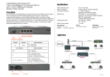
FRM220 Chassis QIG
sales@ctcu.com

FRM220 Chassis QIG
Version 1.0 May, 2020
This QIG supports the following models:
- CH01 - CH01-XX - CH01M-XX
- CH02M-XX - CH02-NMC-XX - CH02-SMT-XX
- CH04A-XX - CH08 - CH20
(Where XX is AC, DC, AA, DD, or AD power options.)
To download this QIG, please visit https://www.ctcu.com/en/download.html
2020 CTC Union Technologies Co., LTD.
All trademarks are the property of their respective owners.
Technical information in this document is subject to change without notice.
CTC Union Technologies Co., Ltd.
Far Eastern Vienna Technology Center
(Neihu Technology Park)
8F, No. 60 Zhouzi St.,
Neihu, Taipei 114, Taiwan
T +886-2-26591021
F +886-2-26590237
E sales@ctcu.com
H www.ctcu.com


Table of Contents
cover .......................................................................................................................................... 1
Introduction ............................................................................................................................... 6
FRM220-CH01 Single Slot Stand-alone Chassis ...................................................................... 7
INSTALLATION ................................................................................................................................................... 7
WALL MOUNTING .............................................................................................................................................. 7
FRM220-CH01/xx Single Slot Stand-alone Chassis with Built-in Power................................. 8
INSTALLATION ................................................................................................................................................... 8
POWER CONNECTION.......................................................................................................................................... 8
WALL MOUNTING .............................................................................................................................................. 9
FRM220-CH01M/xx Single Slot Chassis w/ Built-in Power and Console .............................. 10
INSTALLATION ................................................................................................................................................. 10
WALL MOUNTING ............................................................................................................................................ 10
POWER CONNECTION........................................................................................................................................ 11
FRM220-CH02M-xx Two Slot Standalone Chassis with Console Port .................................. 12
INTRODUCTION ................................................................................................................................................ 12
PANELS ......................................................................................................................................................... 13
INSTALLATION I ................................................................................................................................................ 14
INSTALLATION II ............................................................................................................................................... 14
INSTALLATION III .............................................................................................................................................. 14
RACK MOUNTING OPTION I ................................................................................................................................ 15
RACK MOUNTING OPTION II ............................................................................................................................... 15
WALL MOUNTING OPTION ................................................................................................................................. 15
FRM220-CH02/SMT Two Slot Standalone Chassis ................................................................ 16
DESCRIPTION .................................................................................................................................................. 16
PANELS ......................................................................................................................................................... 17
LED INDICATORS ............................................................................................................................................. 17
POWER & COOLING FAN FAILURE DETECTION FUNCTION ........................................................................................... 18
INSTALLATION I ................................................................................................................................................ 18
RACK MOUNTING OPTION ................................................................................................................................. 18
WALL MOUNTING OPTION ................................................................................................................................. 18
FRM220-CH02/NMC ................................................................................................................. 19
DESCRIPTION .................................................................................................................................................. 19
PANELS ......................................................................................................................................................... 20
LED INDICATORS ............................................................................................................................................. 20
INSTALLATION ................................................................................................................................................. 20
RACK MOUNTING OPTION I ................................................................................................................................ 21
RACK MOUNTING OPTION II ............................................................................................................................... 21
WALL MOUNTING OPTION ................................................................................................................................. 21
FRM220-CH04A Four Slot Stand-alone Chassis .................................................................... 22
INTRODUCTION ................................................................................................................................................ 22
DESCRIPTION .................................................................................................................................................. 22
CHASSIS FRONT DESCRIPTION ............................................................................................................................. 22
CHASSIS REAR DESCRIPTION ............................................................................................................................... 22
CHASSIS PHYSICAL DIMENSIONS........................................................................................................................... 23
CHASSIS SPECIFICATIONS .................................................................................................................................... 23
INSTALLATION ................................................................................................................................................. 24
SITE PREPARATION ........................................................................................................................................... 24
MECHANICAL ASSEMBLY .................................................................................................................................... 24
RACK MOUNTING ............................................................................................................................................. 24
ELECTRICAL INSTALLATION .................................................................................................................................. 24
NMC (SNMP) ............................................................................................................................................... 25
NMC CARD INSTALLATION ................................................................................................................................. 25
LINE CARD INSTALLATION ................................................................................................................................... 25
FRM220-CH08 Eight Slot 19" 1RU Managed Chassis ............................................................ 26
INTRODUCTION ................................................................................................................................................ 26
FUNCTIONAL DESCRIPTION ................................................................................................................................. 26
CHASSIS FRONT DESCRIPTION ............................................................................................................................. 26
LED INDICATORS AND ALARM RELAY .................................................................................................................... 27
CHASSIS REAR DESCRIPTION ............................................................................................................................... 27
CHASSIS PHYSICAL DIMENSIONS........................................................................................................................... 27
CHASSIS SPECIFICATIONS .................................................................................................................................... 28
NMC (SNMP) ............................................................................................................................................... 28
LINE CARD OPTIONS .......................................................................................................................................... 29
INSTALLATION ................................................................................................................................................. 29
SITE PREPARATION ........................................................................................................................................... 29

FRM220 Chassis Quick Installation Guide
5
MECHANICAL ASSEMBLY .................................................................................................................................... 29
RACK MOUNTING ............................................................................................................................................. 29
POWER/FAN MODULES REMOVAL/REPLACEMENT ................................................................................................... 30
ELECTRICAL INSTALLATION .................................................................................................................................. 30
ALARM INSTALLATION ....................................................................................................................................... 30
NMC CARD INSTALLATION ................................................................................................................................. 31
LINE CARD INSTALLATION ................................................................................................................................... 31
FRM220-CH20 Twenty Slot 19" 2RU Managed Chassis ........................................................ 32
INTRODUCTION ................................................................................................................................................ 32
FUNCTIONAL DESCRIPTION ................................................................................................................................. 32
CHASSIS FRONT DESCRIPTION ............................................................................................................................. 32
CHASSIS REAR DESCRIPTION ............................................................................................................................... 33
CHASSIS PHYSICAL DIMENSIONS........................................................................................................................... 33
CHASSIS SPECIFICATIONS .................................................................................................................................... 34
NMC (SNMP) ............................................................................................................................................... 34
LINE CARD OPTIONS .......................................................................................................................................... 35
INSTALLATION ................................................................................................................................................. 35
SITE PREPARATION ........................................................................................................................................... 35
MECHANICAL ASSEMBLY .................................................................................................................................... 35
RACK MOUNTING ............................................................................................................................................. 35
FAN UNITS REMOVAL/REPLACEMENT ................................................................................................................... 36
ELECTRICAL INSTALLATION .................................................................................................................................. 36
ALARM INSTALLATION ....................................................................................................................................... 37
CHASSIS CASCADE ............................................................................................................................................ 38
POWER MODULES REMOVAL/REPLACEMENT .......................................................................................................... 39
LINE CARD INSTALLATION ................................................................................................................................... 40
NMC CARD INSTALLATION ................................................................................................................................. 40
FRM220 Management Quick Start .......................................................................................... 41
INTRODUCTION ................................................................................................................................................ 41
MANAGEMENT METHODS .................................................................................................................................. 41
CONSOLE TERMINAL ......................................................................................................................................... 41
TERMINAL CONNECTION & SETTINGS .................................................................................................................... 41
TERMINAL LOGIN ............................................................................................................................................. 41
TCP/IP SETUP ................................................................................................................................................ 42
TEST TCP/IP CONNECTION ................................................................................................................................ 42
TELNET TERMINAL ............................................................................................................................................ 43
WEB BASED MANAGER ..................................................................................................................................... 43

FRM220 Chassis Quick Installation Guide
Introduction
There are many chassis options for FRM220 line cards. Not all chassis options apply to every line
card model. Chassis range from the simplest CH01 standalone chassis which provides only physical
protection for a one slot line card and includes a 12V@1A (12watt) switching power adapter (wall wart)
to a 20 slot, 2U rack chassis with dual, swappable fans and AC or DC power modules.
This guide will give installation details for each chassis option, including card installation, physical
mounting, power connections and Earth grounding.
This guide is now only available in electronic (PDF) format.
Please skip ahead to your exact chassis model.
CH01
CH01-xx
CH01M-xx
CH02M-xx
CH02-NMC-xx
CH02-SMT-xx
CH04A-xx
CH08
CH20
FRM220 NMC Management Quickstart

FRM220 Chassis Quick Installation Guide
7
FRM220-CH01 Single Slot Stand-alone Chassis
The FRM220-CH01 is designed for tabletop or bench installation. A card slides into the chassis for
a complete, assembled, stand-alone unit. AC power is supplied to FRM220-CH01 through an external
switching AC adapter. (12VDC at 1A)
Installation
Remove the card carefully from packaging after first touching a grounded object, to remove static
charge from your body. Hold the card by the metal face plate and NEVER touch any components on
the board. Align the card with the slots of the CH01 chassis and slide the card all the way in. The DC
power jack will be flush with the rear of the chassis. Use the thumb screw to secure the card,
tightening it only hand tight.
Figure: CH01 Installation
The grounding terminal accepts a 3mm screw (not included). As no ground is provided by the AC
power adapter, connecting an Earth ground to the chassis will provide safety from shock, surge
protection, and through shielding, will reduce both the device's emissions and susceptibility to other
devices' emissions.
Wall Mounting
FRM220-CH01 standalone chassis has the option of adding wall mount capability. One wall mount
kit is required for installing a single standalone chassis on the wall. Each wall mount kit provides a wall
mounting bracket and the screws to attach the bracket to the CH01 chassis. Screws to attach to a wall
are not included.
Use the bracket as a template for drilling holes in a wall and attaching screws. Screws should be
chosen that allow the screw head to pass through the hole in the bracket. The screws in the wall
should be screwed in leaving just enough space so the bracket and CH01 can be hung securely.
Figure: CH01 with Wall Mount Bracket
Operation & Storage Temperature :
- Operating Temperature -- -10°C – 60°C
- Storage Temperature -- -20°C – 70°C
- Humidity -- 10 – 90%
Dimension and Weight: ( W x D x H ) mm
- 88 × 141 × 23 mm
- 358g
WARNING
This is a Class A product. In a domestic environment this product may cause radio interference in
which case the user may be required to take adequate measures.
CE NOTICE
Marking by the symbol CE indicates compliance of this equipment to the EMC directive of the
European Community. Such marking is indicative that this equipment meets or exceeds the following
technical standards: EN 55022:1994/A1:1995/A2:1997 Class A and EN61000-3-2:1995, EN61000-3-
3:1995 and EN50082-1:1997
Grounding
Terminal
DC Input Jack

FRM220 Chassis Quick Installation Guide
8
FRM220-CH01/xx Single Slot Stand-alone Chassis with Built-in Power
The FRM220-CH01/xx is designed for tabletop or bench installation. A card slides into the chassis
for a complete, assembled, stand-alone unit. This chassis features single or dual built-in power
supplies. The build-in AC power supply supports power input from 90~264VAC via an industry
standard IEC power connector. Built-in DC power supplies use a screw terminal block to connect DC
voltage and supports a range of 18~75VDC. Power options include single AC or DC, dual AC
(redundant), dual DC (redundant) or with one AC and one DC (redundant) power supplies.
Installation
Remove the card carefully from packaging after first touching a grounded object, to remove static
charge from your body. Hold the card by the metal face plate and NEVER touch any components on
the board. Align the card with the slots of the CH01/xx chassis and slide the card all the way in. Use
the thumb screw to secure the card, tightening it only hand tight.
Figure: CH01/xx Installation
Power Connection
The graphic below shows the power connections for the CH01-AD, with one DC and one AC power
supply. When two supplies are connected, they are redundant, and the installed card device will
continue operation if only one supply is active.
The DC input utilizes a screw terminal block. Follow the proper polarity for DC, attaching the
negative DC voltage lead to the "-V" terminal and the positive DC voltage lead to the "+V" terminal.
Connect an Earth ground lead to the terminal marked "FG" (frame ground). DC voltage range input is
from 18 to 75VDC.
For AC power input, just firmly seat the IEC type power plug into the jack. The AC voltage range is
100-240VAC +/- 10%. As long as the AC source is grounded, the ground will connect to the CH01/xx
chassis from the IEC connector.
Each power supply has a respective toggle switch which then sends the input power to the internal
supplies. The switch is OFF when set to "0" (zero) and is ON when switched to "1" (one).
Figure: CH01-AD Power Connections
Operation & Storage Temperature :
- Operating Temperature -- -10°C – 60°C
- Storage Temperature -- -20°C – 70°C
- Humidity -- 10 – 90%
Dimension and Weight: ( W x D x H ) mm
- 135 × 198 × 32
- 725g (Single Power), - 770g (Dual Power)

FRM220 Chassis Quick Installation Guide
9
Wall Mounting
FRM220-CH01/xx standalone chassis has the option of adding wall mount capability. Two wall
mount kits are required for installing a single standalone chassis on the wall. Each wall mount kit
provides one wall mounting brackets and the screws to attach the bracket to the CH01/xx chassis.
Screws to attach to a wall are not included.
Use the brackets as a template for drilling holes in a wall and attaching screws. Screws should be
chosen that allow the screw head to pass through the hole in the bracket. The screws in the wall
should be screwed in leaving just enough space so the bracket and CH01/xx can be hung securely.
Figure: CH01/xx with Wall Mount Bracket
WARNING
This is a Class A product. In a domestic environment this product may cause radio interference in
which case the user may be required to take adequate measures.
CE NOTICE
Marking by the symbol CE indicates compliance of this equipment to the EMC directive of the
European Community. Such marking is indicative that this equipment meets or exceeds the following
technical standards: EN 55022:1994/A1:1995/A2:1997 Class A and EN61000-3-2:1995, EN61000-3-
3:1995 and EN50082-1:1997

FRM220 Chassis Quick Installation Guide
10
FRM220-CH01M/xx Single Slot Chassis w/ Built-in Power and Console
The FRM220-CH01M/xx is designed for tabletop or bench installation. A card slides into the
chassis for a complete, assembled, stand-alone unit. This chassis features single or dual built-in
power supplies. The build-in AC power supply supports power input from 90~264VAC via an industry
standard IEC power connector. Built-in DC power supplies use a screw terminal block to connect DC
voltage and supports a range of 18~75VDC. Power options include single AC or DC, dual AC
(redundant), dual DC (redundant) or with one AC and one DC (redundant) power supplies. A Female
DB9 provides local management via serial console (RS232).
Installation
Remove the card carefully from packaging after first touching a grounded object, to remove static
charge from your body. Hold the card by the metal face plate and NEVER touch any components on
the board. Align the card with the slots of the CH01M/xx chassis and slide the card all the way in. Use
the thumb screw to secure the card, tightening it only hand tight.
Figure: CH01M/xx Installation
The DB9F is a DCE to a PC's DTE COM port, providing a simple 1:1 connection with the supplied
DB9F to DB9M 1 meter cable. See the technical sheet for the installed card to understand the serial
port settings required to manage that card.
Wall Mounting
FRM220-CH01M/xx standalone chassis have the option of adding wall mount capability. One wall
mount kit is required for installing a single standalone chassis on the wall. Each wall mount kit
provides two wall mounting brackets and the screws to attach the bracket to the CH01M/xx chassis.
Screws to attach to a wall are not included.
Use the brackets as a template for drilling holes in a wall and attaching screws. Screws should be
chosen that allow the screw head to pass through the hole in the bracket. The screws in the wall
should be screwed in leaving just enough space so the bracket and CH01M/xx can be hung securely.
Figure: CH01M/xx with Wall Mount Bracket

FRM220 Chassis Quick Installation Guide
11
Power Connection
The graphic below shows the power connections for the CH01M-AD, with one DC and one AC
power supply. When two supplies are connected, they are redundant, and the installed card device will
continue operation if only one supply is active.
The DC input utilizes a screw terminal block. Follow the proper polarity for DC, attaching the
negative DC voltage lead to the "-V" terminal and the positive DC voltage lead to the "+V" terminal.
Connect an Earth ground lead to the terminal marked "FG" (frame ground). DC voltage range input is
from 18 to 75VDC.
For AC power input, just firmly seat the IEC type power plug into the jack. The AC voltage range is
100-240VAC +/- 10%. As long as the AC source is grounded, the ground will connect to the CH01/xx
chassis from the IEC connector.
Each power supply has a respective toggle switch which then sends the input power to the internal
supplies. The switch is OFF when set to "0" (zero) and is ON when switched to "1" (one).
Figure: CH01M-AD Power Connections
Operation & Storage Temperature :
- Operating Temperature -- -10°C – 60°C
- Storage Temperature -- -20°C – 70°C
- Humidity -- 10 – 90%
Dimension and Weight: ( W x D x H ) mm
- 135 × 200 × 32
- 730g (Single Power), - 775g (Dual Power)
WARNING
This is a Class A product. In a domestic environment this product may cause radio interference in
which case the user may be required to take adequate measures.
CE NOTICE
Marking by the symbol CE indicates compliance of this equipment to the EMC directive of the
European Community. Such marking is indicative that this equipment meets or exceeds the following
technical standards: EN 55022:1994/A1:1995/A2:1997 Class A and EN61000-3-2:1995, EN61000-3-
3:1995 and EN50082-1:1997

FRM220 Chassis Quick Installation Guide
12
FRM220-CH02M-xx Two Slot Standalone Chassis with Console Port
Introduction
The FRM220 chassis product line includes various metal chassis sizes, which can hold from one to
twenty FRM220 slide-in modules. The FRM220-CH02M & FRM220-CH02M-HP are a two-slot chassis
with built-in cooling fans and DB9 console port for local management, which can be installed with
either one or two single width blade cards or one double width blade card. The available power
supplies are built-in AC, DC or AC+DC dual power. The line cards used in FRM220-CH02M &
FRM220-CH02M-HP two slots chassis include 10G, 2.7G 3R Transponder, 1/5E1/8E1/16E1 to
Ethernet E1 Inverse Multiplexer, FOM04 Fiber Optical Multiplexer, 10/100i Fast Ethernet In-band
managed converter, E1/T1 fiber modem and V35/X21/RS530 fiber modem.
Features
Two slot chassis for FRM220 line cards.
Support backplane connection between two slots.
Support DB9 console port for local management.
Support either one or two single width blades or one double width blade.
Support built-in AC, DC, AC+DC power supplies.
Support built-in heat sink cooling Fan.
Specifications
Slot Capacity: 2 slots chassis with DB9 RS-232 console port
LED Indications: PWR 1 & PWR 2
Power:
- Power Types: AC, DC, AD (AC + DC), AA (AC + AC), DD (DC + DC)
- AC Power Supply: 100 ~ 240VDC ±10%
- DC power supply: 18 ~ 72VDC
- Power Consumption: 30W
Operation & Storage Temperature:
- Operating Temperature: 0°C ~ 50°C
- Storage Temperature: 0°C ~ 70°C
- Humidity: 5% ~ 90%
Dimensions
- FRM220-CH02M: 222.7mm (D) x 45.5mm (W) x 167.4mm (H)
- FRM220-CH02M-HP: 222.7mm (D) x 49.5mm (W) x 177.4mm (H)
Weight: 1300g (FRM220-CH02M), 1380 (FRM220-CH02M-HP)
Emission / Safety: FCC Part 15 Class A, CE Mark, RoHS

FRM220 Chassis Quick Installation Guide
13
Panels
Figure. Front Panel
Figure. Rear Panels
LED Indicators and Console port
LED Indications:
- PWR 1: LED on/off Power 1 is on / Power 1 is off
- PWR 2: LED on/off Power 2 is on / Power 2 is off
Console slot select switch:
- Slot 1: console port for slot 1 (upper) line card configuration
- Slot 2: console port for slot 2 (lower) line card configuration
DC + DC
Power
Type
AC + AC
Power
Type
AC + DC
Power
Type
One DC
Power
Type
One AC
Power
Type
Slot 1
Slot 2
Console Port
Power LED
Indicators
Console Port
Select Switch

FRM220 Chassis Quick Installation Guide
14
Installation I
The FRM220-CH02M & FRM220-CH02M-HP, a two blade chassis, can be installed with one
double width blade line card into the chassis. The line cards include Imux16 E1Inverse Multiplexer or
FOM04 (GFOM04) 4ch E1/T1 Fiber Optical Multiplexer. The FRM220-CH02M & FRM220-CH02M-HP
also support DB9 console port for standalone local management.
Two Slot local line card Management Serial Console
Figure. Module Line Card Installation
Installation II
The FRM220-CH02M & FRM220-CH02M-HP, a two blade chassis, can be installed with one single
width blade line card into the chassis. The line cards include 10G, 2.7G, 4G Transponder, E1 Inverse
multiplexer, 10/100i, E1/T1, ….etc.
Figure. One-Module Line Card Installation
Installation III
The FRM220-CH02M & FRM220-CH02M-HP, a two blade chassis, can be installed with two single
width blade line cards into the chassis. The line cards include E1Inverse multiplexer, 10/100i, E1/T1,
V35/X21/RS530, FXO/FXS….etc.
Figure. Two-Module Line Card Installation
One-Module Line Card
Local Management
Card 1
Card 2
Local Management

FRM220 Chassis Quick Installation Guide
15
Rack Mounting Option I
FRM220-CH02M & FRM220-CH02M-HP standalone chassis have the option of adding standard EIA
19" rack mount capability. The rack mount ear provides for mounting a single standalone chassis in a
rack. Each rack mount ear kit provides all the necessary hardware for a complete installation.
Figure. Rack Mount Ear
Rack Mounting Option II
FRM220-CH02M & FRM220-CH02M-HP standalone chassis have the option of adding standard EIA
19" rack mount capability. The rack mount tray provides mounting for two standalone chassis in a
rack. Each rack mount tray kit provides all the necessary hardware for a complete installation.
Figure. Rack Mount Tray
Wall Mounting Option
FRM220-CH02M & FRM220-CH02M-HP standalone chassis have the option of adding wall mount
capability. Two wall mount kits are required for installing a single standalone chassis on the wall. Each
wall mount kit provides all the necessary hardware for a complete installation.
Figure. Wall Mount Kit Installation

FRM220 Chassis Quick Installation Guide
16
FRM220-CH02/SMT Two Slot Standalone Chassis
Description
The FRM220 chassis product line includes various metal chassis sizes, which can hold from one to
twenty FRM220 slide-in modules. The FRM220-CH02/SMT is a two-slot chassis, which can be SNMP
managed when installing one FRM220-NMC Network Management Controller card into the chassis for
Web, Telnet, Console and SNMP management. In addition, the FRM220-CH02/SMT provides power
and cooling fan failure alarm detection via NMC card. The available power supplies are built-in AC,
DC, 2 AC, 2 DC or AC+DC dual power.
All types of single slot FRM220 series cards can be installed into FRM220-CH02/SMT two-slot
chassis such as 10G, 2.7G 3R Transponder, 1E1/5E1/8E1 to Ethernet E1 Inverse Multiplexer,
Ethernet over Fiber, E1/T1, 35/X21/RS530 fiber modem, POTS over fiber, and RS485/422/232 fiber
converter.
Features
Two-slot chassis for FRM220 line cards
Support backplane connection between two slots
Telnet, Web, Console, SNMP manageable via NMC card
Support one single width blade plus NMC (Network Management Controller)
Support built-in AC, DC, 2 AC, 2 DC, AC+DC power supplies
Support built-in heat sink cooling Fan
Support power and cooling fan failure alarm detection
Specifications
Slot Capacity: 2 slots chassis with SNMP Management via NMC card
LED Indications: PWR 1, PWR 2, FAN 1, FAN 2
Power:
- Power Types: AC, DC, AA (AC + AC), DD (DC + DC), AD (AC + DC)
- AC Power Supply: 100 ~ 240VDC ±10%
- DC power supply: 18 ~ 72VDC
- Power Consumption: 30W
Operation & Storage Temperature:
- Operating Temperature: 0°C ~ 50°C
- Storage Temperature: 0°C ~ 70°C
- Humidity: 5% ~ 90%
Dimension: 205mm (D) x 44.7mm (W) x 220mm (H)
Weight: 1.5kg
Emission / Safety: FCC Part 15 Class A, CE Mark, RoHS

FRM220 Chassis Quick Installation Guide
17
Panels
Figure. Front Panel
Note: For Telnet, Web, Console and SNMP management, NMC
card must be inserted in Slot 2.
Figure. Rear Panel
LED Indicators
LED
Status
Definition
PWR1
PWR2
Steady Green
The chassis receives power current from power
1 or 2.
Green
Blinking
Power current is zero (in standby mode).
Steady Red
Power voltage is smaller than 9V or power
current is over 2500 mA.
(Voltage < 9V or Current > 2500 mA)
Red Blinking
Power voltage is larger than 10.5V but smaller
than 9V or power current is larger than "2500 *
90% mA" but smaller than 2500 mA.
(10.5V < Voltage < 9V or 2500 * 90% mA <
Current < 2500 mA)
Off
Turn off the PWR 1 or 2 LED indicator via the
NMC card.
FAN1
FAN2
Steady Green
Fan is working normally.
Red Blinking
Current fan speed (RPM) is slow than "fan
speed * 60%".
Steady Red
Current fan speed (RPM) is slow than "fan
speed * 20%.
Off
- Power current is smaller than 300 mA. (in Auto
Sensor mode)
- Fan is off or not working.
Slot 1
Slot 2
Power & FAN
LED Indicators
DC + DC
Power
Type
AC + AC
Power
Type
AC + DC
Power
Type
One DC
Power
Type
One AC
Power
Type

FRM220 Chassis Quick Installation Guide
18
Power & Cooling Fan Failure Detection Function
FRM220-CH02/SMT standalone chassis supports "Power & Cooling Fan Failure Detection"
function. When power warning or failure occurs, users can immediately be notified of the warning or
fault via power LED indicator or "Status" page via NMC card (if this card is inserted).
For fan failure detection, the chassis will use "Auto Sensor" default mode to decide the fan speed if
the NMC card is not used. "Auto Sensor" mode will sense the fan speed depending on the power
current automatically and issue LED warning or alarm notice when the condition meets the threshold
value. When NMC card is inserted, users can select the desired fan speed. Available fan speed
options are FAN 0 (FAN off), FAN1, FAN2, FAN3, FAN4 (Full Speed).
Installation I
The FRM220-CH02/SMT, a two-slot chassis, may be applied in point to point applications or may
be linked to a centrally located FRM220 CH20 rack. It can be installed with one single width blade line
card into the chassis. All types of FRM220 series one module line card can be installed in FRM220-
CH02/SMT chassis, including 10G 3R Transponder, 2.7G 3R Transponder, E1/5E1/8E1 Inverse
multiplexer, Ethernet over fiber, E1/T1, 35/X21/RS530 fiber modem, POTS over fiber, and
RS485/422/232 fiber converter. To use the NMC card, it must be inserted in Slot 2.
Figure. One-Module Line Card Installation plus NMC
Rack Mounting Option
FRM220-CH02/SMT standalone chassis has the option of adding standard EIA 19" rack mount
capability. The rack mount ear (optional accessory) provides for mounting a single standalone chassis
in a rack. Each rack mount ear kit provides all the necessary hardware for a complete installation.
Figure. Attaching Rack Mount Ear
Wall Mounting Option
FRM220-CH02/SMT standalone chassis has the option of adding wall mount capability. Two wall
mount kits are required for installing a single standalone chassis on the wall. Each wall mount kit
provides all the necessary hardware for a complete installation.
Figure. Wall Mount Kit Installation
NMC Card
One-Module Line Card

FRM220 Chassis Quick Installation Guide
19
FRM220-CH02/NMC
Description
The FRM220 chassis product line includes various metal chassis sizes, which can hold from one to
twenty FRM220 slide-in modules. The FRM220-CH02/NMC is a two slot chassis, which can be SNMP
managed when installing one FRM220-NMC Network Management Controller card into the chassis for
Web, Telnet, Console and SNMP management. The FRM220-CH02/NMC is meant to be installed with
one single width blade card plus an NMC card.
The available power supplies are built-in AC, DC or AC+DC dual power. All types of FRM220
series single slot cards can be installed into FRM220-CH02/NMC two slots chassis such as 10G, 2.7G
3R Transponder, 1E1/5E1/8E1 to Ethernet E1 Inverse Multiplexer, Ethernet over Fiber, E1/T1,
35/X21/RS530 fiber modem, POTS over fiber, and RS485/422/232 fiber converter.
Features
Two slot chassis for FRM220 line cards
Support backplane connection between two slots
Telnet, Web, Console, SNMP manageable via NMC card
Support one single width blade card plus NMC
Support built-in AC, DC, AC+DC power supplies
Support built-in cooling Fans
Specifications
Slot Capacity: 2 slots chassis with SNMP Management via NMC card
LED Indications: PWR 1 & PWR 2
Power:
- Power Types: AC, DC, AD (AC + DC), AA (AC + AC), DD (DC + DC)
- AC Power Supply: 100 ~ 240VDC ±10%
- DC power supply: 18 ~ 72VDC
- Power Consumption: 30W
Operation & Storage Temperature:
- Operating Temperature: 0°C ~ 50°C
- Storage Temperature: 0°C ~ 70°C
- Humidity: 5% ~ 90%
Dimension
- FRM220-CH02/NMC: 222.7mm (D) x 45.5mm (W) x 167.4mm (H)
- FRM220-CH02/NMC-HP: 222.7mm (D) x 49.5mm (W) x 177.4mm (H)
Weight: 1000g (FRM220-CH02/NMC), 1100g (FRM220-CH02/NMC-HP)
Emission / Safety: FCC Part 15 Class A, CE Mark, RoHS

FRM220 Chassis Quick Installation Guide
20
Panels
Figure. Front Panel
Note: For Telnet, Web, Console and SNMP management, NMC
card must be inserted in Slot 2.
Figure. Rear Panel
LED Indicators
LED Indications:
- PWR 1: LED on/off Power 1 is on / Power 1 is off
- PWR 2: LED on/off Power 2 is on / Power 2 is off
Installation
The FRM220-CH02/NMC, a two blade chassis, can be installed with one single width blade line
card plus an NMC card into the chassis. The line cards include E1 Inverse multiplexer, 10/100i, E1/T1,
V35/X21/RS530, FXO/FXS….etc.
Figure. Line Card plus NMC Installation
Slot 1
Slot 2
Power LED
Indicators
DC + DC
Power
Type
AC + AC
Power
Type
AC + DC
Power
Type
One DC
Power
Type
One AC
Power
Type
NMC Card
One-Module Line Card
/