Supermicro SuperServer 6026TT-HIBQRF User manual
- Category
- Server barebones
- Type
- User manual
This manual is also suitable for

SUPER
USER'S MANUAL
Revision 1.0d
®
SuperServer 6026TT-HTF
SuperServer 6026TT-HTRF
SuperServer 6026TT-HIBXF
SuperServer 6026TT-HIBXRF
SuperServer 6026TT-HIBQF
SuperServer 6026TT-HIBQRF

The information in this User’s Manual has been carefully reviewed and is believed to be accurate.
The vendor assumes no responsibility for any inaccuracies that may be contained in this document,
makes no commitment to update or to keep current the information in this manual, or to notify any
person or organization of the updates. Please Note: For the most up-to-date version of this
manual, please see our web site at
www.supermicro.com.
Super Micro Computer, Inc. ("Supermicro") reserves the right to make changes to the product
described in this manual at any time and without notice. This product, including software and
documentation, is the property of Supermicro and/or its licensors, and is supplied only under a
license. Any use or reproduction of this product is not allowed, except as expressly permitted by
the terms of said license.
IN NO EVENT WILL SUPERMICRO BE LIABLE FOR DIRECT, INDIRECT, SPECIAL, INCIDENTAL,
SPECULATIVE OR CONSEQUENTIAL DAMAGES ARISING FROM THE USE OR INABILITY TO
USE THIS PRODUCT OR DOCUMENTATION, EVEN IF ADVISED OF THE POSSIBILITY OF
SUCH DAMAGES. IN PARTICULAR, SUPERMICRO SHALL NOT HAVE LIABILITY FOR ANY
HARDWARE, SOFTWARE, OR DATA STORED OR USED WITH THE PRODUCT, INCLUDING THE
COSTS OF REPAIRING, REPLACING, INTEGRATING, INSTALLING OR RECOVERING SUCH
HARDWARE, SOFTWARE, OR DATA.
Any disputes arising between manufacturer and customer shall be governed by the laws of Santa
Clara County in the State of California, USA. The State of California, County of Santa Clara shall
be the exclusive venue for the resolution of any such disputes. Super Micro's total liability for all
claims will not exceed the price paid for the hardware product.
FCC Statement: This equipment has been tested and found to comply with the limits for a Class
A digital device pursuant to Part 15 of the FCC Rules. These limits are designed to provide
reasonable protection against harmful interference when the equipment is operated in a commercial
environment. This equipment generates, uses, and can radiate radio frequency energy and, if not
installed and used in accordance with the manufacturer’s instruction manual, may cause harmful
interference with radio communications. Operation of this equipment in a residential area is likely
to cause harmful interference, in which case you will be required to correct the interference at your
own expense.
California Best Management Practices Regulations for Perchlorate Materials: This Perchlorate
warning applies only to products containing CR (Manganese Dioxide) Lithium coin cells. “Perchlorate
Material-special handling may apply. See
www.dtsc.ca.gov/hazardouswaste/perchlorate”
WARNING: Handling of lead solder materials used in this
product may expose you to lead, a chemical known to
the State of California to cause birth defects and other
reproductive harm.
Manual Revision 1.0d
Release Date: May 08, 2013
Unless you request and receive written permission from Super Micro Computer, Inc., you may not
copy any part of this document.
Information in this document is subject to change without notice. Other products and companies
referred to herein are trademarks or registered trademarks of their respective companies or mark
holders.
Copyright © 2013 by Super Micro Computer, Inc.
All rights reserved.
Printed in the United States of America

Preface
About This Manual
This manual is written for professional system integrators and PC technicians.
It provides information for the installation and use of the SuperServer
6026TT-HT(R)F/HIBX(R)F/HIBQ(R)F. Installation and maintenance should be
performed by experienced technicians only.
The SuperServer 6026TT-HT(R)F/HIBX(R)F/HIBQ(R)F is a 2U Twin
2
(four
serverboards/nodes in a 2U chassis) rackmount server based on the SC827H-(R)1400B
server chassis and six serverboards (Super X8DTT-H(F)/HIBX(F)/HIBQ(F)) An
optional redundant power supply may be added to the system (indicated by the
"(R)" in the product name). The "(H)" in the product name indicates that the system
is cableless.
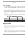
The main differences between the various serverboards, and the servers they are
in, is shown in the table below:
Model Variations (Differences between X8DTT-H models)
X8DTT-H /-HF /-HIBX /-HIBXF /-HIBQ /HIBQF
IPMI 2.0 w/ KVM
Over LAN
No Yes No Yes No Yes
Infi niBand
Connection
No No Yes Yes Yes Yes
DDR IB
No No Yes Yes No No
QDR IB
No No No No Yes Yes
Manual Organization
Chapter 1: Introduction
The fi rst chapter provides a checklist of the main components included with the server
system and describes the main features of the Super X8DTT-H(F)/HIBX(F)/HIBQ(F)
serverboard and the SC827H-(R)1400B chassis.
Chapter 2: Server Installation
This chapter describes the steps necessary to install the SuperServer
6026TT-HT(R)F/HIBX(R)F/HIBQ(R)F into a rack and check out the server
confi guration prior to powering up the system. If your server was ordered without
the processor and memory components, this chapter will refer you to the appropriate
sections of the manual for their installation.
iii
Preface

SUPERSERVER 6026TT-HT(R)F/HIBX(R)F/HIBQ(R)F User's Manual
iv
Chapter 3: System Interface
Refer to this chapter for details on the system interface, which includes the functions
and information provided by the control panel on the chassis as well as other LEDs
located throughout the system.
Chapter 4: System Safety
You should thoroughly familiarize yourself with this chapter for a general overview
of safety precautions that should be followed when installing and servicing the
SuperServer 6026TT-HT(R)F/HIBX(R)F/HIBQ(R)F.
Chapter 5: Advanced Serverboard Setup
Chapter 5 provides detailed information on the X8DTT-H(F)/HIBX(F)/HIBQ(F)
serverboard, including the locations and functions of connectors, headers and
jumpers. Refer to this chapter when adding or removing processors or main memory
and when reconfi guring the serverboard.
Chapter 6: Advanced Chassis Setup
Refer to Chapter 6 for detailed information on the SC827H-(R)1400B 2U rackmount
server chassis. You should follow the procedures given in this chapter when
installing, removing or reconfi guring SATA or peripheral drives and when replacing
system power supply units and cooling fans.
Chapter 7: BIOS
The BIOS chapter includes an introduction to BIOS and provides detailed information
on running the CMOS Setup Utility.
Appendix A: BIOS Error Beep Codes
Appendix B: Installing Windows
Appendix C: System Specifi cations

v
Preface
Notes

vi
SUPERSERVER 6026TT-HT(R)F/HIBX(R)F/HIBQ(R)F USER'S MANUAL
Table of Contents
Chapter 1 Introduction
1-1 Overview .........................................................................................................1-1
1-2 Serverboard Features .....................................................................................1-2
Processors ...................................................................................................... 1-2
Memory ........................................................................................................... 1-2
Serial ATA ........................................................................................................1-2
PCI Expansion Slots ....................................................................................... 1-2
Ethernet Ports .................................................................................................1-3
Onboard Controllers/Ports ..............................................................................1-3
Graphics Controller ......................................................................................... 1-3
Other Features ................................................................................................1-3
Infi niBand ........................................................................................................1-3
1-3 Server Chassis Features ................................................................................1-5
System Power ................................................................................................. 1-5
SATA Subsystem ............................................................................................. 1-5
Control Panel .................................................................................................. 1-5
Rear I/O Panel ................................................................................................ 1-5
Cooling System ...............................................................................................1-5
1-4 Advanced Power Management (for -F Models Only) ..................................... 1-6
Intel® Intelligent Power Node Manager (NM) .................................................1-6
Manageability Engine (ME) ............................................................................. 1-6
1-5 Contacting Supermicro ....................................................................................1-7
1-6 2U Twin
2
: System Notes ................................................................................. 1-8
Nodes ..............................................................................................................1-8
System Power ................................................................................................. 1-8
SATA Backplane/Drives ...................................................................................1-8
Chapter 2 Server Installation
2-1 Overview .........................................................................................................2-1
2-2 Unpacking the System .................................................................................... 2-1
2-3 Preparing for Setup ......................................................................................... 2-1
Choosing a Setup Location ............................................................................. 2-2
2-4 Warnings and Precautions .............................................................................. 2-2
Rack Precautions ............................................................................................ 2-2
Server Precautions .......................................................................................... 2-2
Rack Mounting Considerations ....................................................................... 2-3
Ambient Operating Temperature ................................................................ 2-3

vii
Table of Contents
Reduced Airfl ow .........................................................................................2-3
Mechanical Loading ................................................................................... 2-3
Circuit Overloading ..................................................................................... 2-3
Reliable Ground ......................................................................................... 2-4
Removing the Protective Film ......................................................................... 2-4
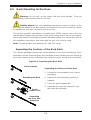
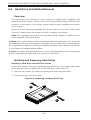
2-5 Rack Mounting Instructions ............................................................................. 2-5
Separating the Sections of the Rack Rails ..................................................... 2-5
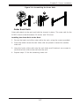
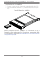
Installing the Inner Rail Extensions ................................................................2-6
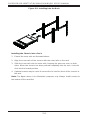
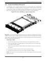
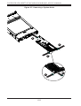
Outer Rack Rails ............................................................................................. 2-7
2-6 Checking the Serverboard Setup .................................................................... 2-9
2-7 Preparing to Power On ................................................................................. 2-10
Chapter 3 System Interface
3-1 Overview .........................................................................................................3-1
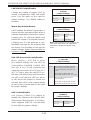
3-2 Control Panel Buttons ..................................................................................... 3-1
Power ..............................................................................................................3-1
UID ..................................................................................................................3-1
3-3 Control Panel LEDs ........................................................................................ 3-2
Alert .................................................................................................................3-2
NIC ..................................................................................................................3-2
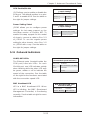
3-4 SATA Drive Carrier LEDs ................................................................................ 3-2
Chapter 4 Standardized Warning Statements for AC Systems
4-1 About Standardized Warning Statements .......................................................4-1
Warning Defi nition ........................................................................................... 4-1
Installation Instructions ....................................................................................4-4
Circuit Breaker ................................................................................................ 4-5
Power Disconnection Warning ........................................................................4-6
Equipment Installation ..................................................................................... 4-8
Restricted Area ................................................................................................ 4-9
Battery Handling ............................................................................................4-10
Redundant Power Supplies ..........................................................................4-12
Backplane Voltage ........................................................................................4-13
Comply with Local and National Electrical Codes ........................................4-14
Product Disposal ........................................................................................... 4-15
Hot Swap Fan Warning ................................................................................. 4-16
Power Cable and AC Adapter ...................................................................... 4-18

viii
SUPERSERVER 6026TT-HT(R)F/HIBX(R)F/HIBQ(R)F USER'S MANUAL
Chapter 5 Advanced Serverboard Setup
5-1 Handling the Serverboard ............................................................................... 5-1
Precautions ..................................................................................................... 5-1
Unpacking ....................................................................................................... 5-1
5-2 Serverboard Installation ..................................................................................5-2
5-3 Connecting Cables ..........................................................................................5-2
Connecting Data Cables ................................................................................. 5-3
Connecting Power Cables ..............................................................................5-3
Connecting the Control Panel ......................................................................... 5-3
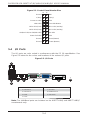
5-4 I/O Ports ..........................................................................................................5-4
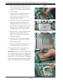
5-5 Processor and Heatsink Installation................................................................5-5
Installing LGA1366 Processors ....................................................................... 5-5
Installing a CPU Heatsink ............................................................................... 5-7
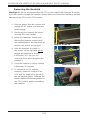
Removing the Heatsink ...................................................................................5-8
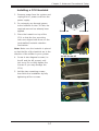
5-6 Installing Memory ............................................................................................ 5-9
Memory Support .............................................................................................. 5-9
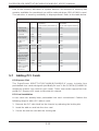
5-7 Adding PCI Cards ......................................................................................... 5-12
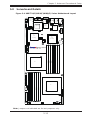
5-8 Serverboard Details ...................................................................................... 5-13
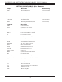
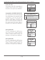
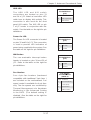
5-9 Connector Defi nitions ....................................................................................5-15
5-10 Jumper Settings ............................................................................................5-21
5-11 Onboard Indicators ........................................................................................5-23
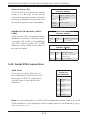
5-12 Serial ATA Connections ................................................................................. 5-24
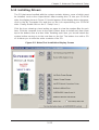
5-13 Installing Drivers ............................................................................................5-25
Supero Doctor III ........................................................................................... 5-26
5-14 Serverboard Battery ......................................................................................5-28
Chapter 6 Advanced Chassis Setup
6-1 Static-Sensitive Devices ..................................................................................6-1
Precautions ..................................................................................................... 6-1
Unpacking ....................................................................................................... 6-1
6-2 Control Panel ..................................................................................................6-2
6-3 System Fans ...................................................................................................6-2
Fan Confi guration ............................................................................................ 6-3
System Fan Failure ......................................................................................... 6-3
6-4 Hard Drive Installation/Removal......................................................................6-4
Overview ......................................................................................................... 6-4
Installing and Removing Hard Drives .............................................................6-4
6-5 Node Installation/Removal .............................................................................. 6-7
6-6 Installing the Air Shrouds ................................................................................ 6-9

Air Shrouds ..................................................................................................... 6-9
6-7 Power Supply .................................................................................................. 6-9
Power Supply Failure: Single Power Supply Module ..................................... 6-9
Power Supply Failure: Redundant Power (Two Modules) ............................ 6-10
Chapter 7 BIOS
7-1 Introduction ......................................................................................................7-1
Starting BIOS Setup Utility .............................................................................. 7-1
How To Change the Confi guration Data .........................................................7-1
Starting the Setup Utility ................................................................................. 7-2
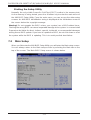
7-2 Main Setup ......................................................................................................7-2
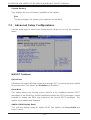
7-3 Advanced Setup Confi gurations......................................................................7-4
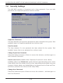
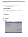
7-4 Security Settings ...........................................................................................7-24
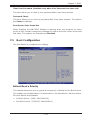
7-5 Boot Confi guration ........................................................................................ 7-25
7-6 Exit Options ...................................................................................................7-26
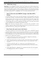
7-7 BIOS Recovery ............................................................................................. 7-28
How to Recover the AMIBIOS Image (-the Main BIOS Block) ..................... 7-28
Boot Sector Recovery from a USB Device ..............................................7-28
Boot Sector Recovery from an IDE CD-ROM .......................................... 7-29
Boot Sector Recovery from a Serial Port ("Serial Flash") ....................... 7-29
Appendix A BIOS Error Beep Codes
A-1 BIOS Error Beep Codes .................................................................................A-1
Appendix B System Specifi cations
Table of Contents

Notes
SUPERSERVER 6026TT-HT(R)F/HIBX(R)F/HIBQ(R)F USER'S MANUAL

Chapter 1
Introduction
1-1 Overview
The SuperServer 6026TT-HT(R)F/HIBX(R)F/HIBQ(R)F is a "2U Twin
2
"
server comprised of the SC827H-(R)1400B 2U chassis and four
X8DTT-H(F)/HIBX(F)/HIBQ(F) serverboards. Please refer to our web site for
information on operating systems that have been certified for use with the
SuperServer 6026TT-HT(R)F/HIBX(R)F/HIBQ(R)F (www.supermicro.com).
In addition to the serverboard and chassis, various hardware components may have
been included with the system, as listed below.
• Eight passive CPU heatsinks (SNK-P0037P)
• Four 8-cm cooling fans (FAN-0111L4)
• Four air shrouds (MCP-310-82706-0B)
• SATA Accessories:
Twelve SATA hard drive carriers (three per node) (MCP-220-00024-0B)
One internal HDD backplane (BPN-SAS-827B)
• Four PCI Express x16 riser cards (RSC-R1U-E16R)
• Rackmount rails kit (MCP-290-00053-0N)
Note: The SuperServer 6026TT-HT(R)F/HIBX(R)F/HIBQ(R)F system is cableless
and does not need or come with SATA cables.
Note: For your system to work properley, please follow the links below to download
all necessary drivers/utilities and the user’s manual for your server.
• SMCI product manuals: http://www.supermicro.com/support/manuals/
• Product drivers and utilities: ftp://ftp.supermicro.com
• Product safety information:
http://super-dev/about/policies/safety_information.cfm
• If you have any questions, please contact our support team at:
Chapter 1: Introduction
1-1

1-2
SUPERSERVER 6026TT-HT(R)F/HIBX(R)F/HIBQ(R)F USER'S MANUAL
1-2 Serverboard Features
At the heart of the SuperServer 6026TT-HT(R)F/HIBX(R)F/HIBQ(R)F are four
X8DTT-H(F)/HIBX(F)/HIBQ(F) dual processor serverboards, which are based on
Intel's 5520 (North Bridge) + ICH10R (South Bridge) chipset. Below are the main
features of the serverboards. Note that the features on each board are quadrupled
for the server, which includes four nodes.
Processors
Each X8DTT-H(F)/HIBX(F)/HIBQ(F) supports two Intel® 5500/5600 series
processors in LGA 1366 sockets (up to 95w). Please refer to our web site for a
complete listing of supported processors (www.supermicro.com).
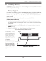
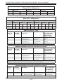
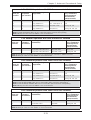
Memory
Each X8DTT-H(F)/HIBX(F)/HIBQ(F) has twelve (12) DIMM sockets that can support
up to 192 GB of registered ECC DDR3-1333/1066/800 MHz speed SDRAM, or
48 GB of Unbuffered ECC/Non-ECC DDR3-1333/1066/800 MHz speed memory
(with max. 4 GB of Registered ECC and 2 GB of Unbuffered memory per DIMM
slot.) for a maximum of 192 GB for the system. See Chapter 5 for more details on
installing memory into the system.
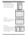
Serial ATA
The South Bridge (ICH10R) of the chipset includes a Serial ATA controller for six
Gb/s SATA drives. The hot-swappable SATA drives are connected to a backplane
that provides power, bus termination and confi guration settings. RAID 0, 1, 5 and 10
are supported. Refer to the support area of our web site for procedures on setting
up RAID on your system.
PCI Expansion Slots
Each X8DTT-H(F)/HIBX(F)/HIBQ(F) board has 1x PCI Express 2.0 x16 slot, so four
PCI Express 2.0 x16 slots (for low-profi le expansion cards) are provided in the server.
In the SuperServer 6026TT-HT(R)F/HIBX(R)F/HIBQ(R)F server confi guration, riser
cards have been pre-installed to support low-profi le add-on cards.

Chapter 1: Introduction
1-3
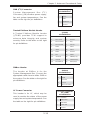
Ethernet Ports
An Intel® network controller is integrated into each of the serverboards to support
two Gigabit LAN ports (100/1000Base-T/1000BaseTX, RJ45 output).
Onboard Controllers/Ports
Onboard I/O backpanel ports on each serverboard include one COM port, a VGA
port, two USB ports, a dedicated IPMI LAN port and two Gigabit LAN (NIC) ports.
An Infi niBand port is also included on the X8DTT-HIBXF/-HIBQF serverboards
(the 6026TT-HIBX(R)F and 6026TT-HIBQ(R)F only). Up to four USB 2.0 (Universal
Serial Bus) connections (2 Rear USB Ports and 1 Type A Header w/2 USB
connections supported) are on each of the servers. There are four sets of I/O ports
included in the server (one set for each serverboard).
Graphics Controller
The X8DTT-H(F)/HIBX(F)/HIBQ(F) features an integrated Matrox G200eW graphics
chip, which includes 8 MB of DDR2 memory.
Other Features
Other onboard features that promote system health include voltage monitors, auto-
switching voltage regulators, chassis and CPU overheat sensors, virus protection
and BIOS rescue.
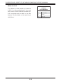
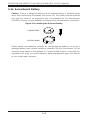
Infi niBand
Both the 6026TT-HIBX(R)F and 6026TT-HIBQ(R)F include an Infi niBand port at
DDR (dual data rate) and QDR (quad data rate) speeds, respectively. Infi niBand
is a scalable serial communications link intended for connecting processors with
high-speed peripherals. (Infi niBand requires a QSFP connector.)

1-4
SUPERSERVER 6026TT-HT(R)F/HIBX(R)F/HIBQ(R)F USER'S MANUAL
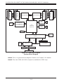
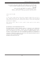
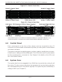
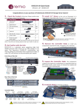
Figure 1-1. Intel 5520 Chipset:
System Block Diagram
Note1: This is a general block diagram. Please see Chapter 5 for details.
Note2: The Intel 5500 (IOH-24D) chipset is available for OEM only.
PROCESSOR#0
#1
#1
#1
#2
DDR3 DIMM
#2
#2
DDR3 DIMM
#1
#1
#1
DDR3 DIMM
#2
#2
#2
DDR3 DIMM
C
C
A
A
B
B
DD
E
E
FF
IOH
5520/5500
36-D/24-D
ICH10R
Intel
82574
BMC/VGA
VGA CONN
DDR II
PCI
4 SATA
LPC
SPI
AT25
DF321
MT25408
Connect-X IB
PCI-E Gen2/DDR or QDR
(For 36D Only)
QSFP
RTL8201N PHY
Dedicated LAN
LPCIO W83527
RMII
PCI-E
x16 Slot
Hotswap Connector
Intel
82574
PROCESSOR#1
RJ-45
RJ-45
QPI

Chapter 1: Introduction
1-5
1-3 Server Chassis Features
The following is a general outline of the main features of the SC827H-(R)1400B 2U
chassis. Details on the chassis can be found in Chapter 6.
System Power
When confi gured as a SuperServer 6026TT-HT(R)F/HIBX(R)F/HIBQ(R)F, the
SC827H-(R)1400B includes a single 1400 Watt power supply, which provides power
to all four serverboards (nodes). An additional 1400 Watt power supply module
(not included) may be installed to provide redundant power for the 6026TT-HTRF/
HIBXRF/HIBQRF models.
SATA Subsystem
The SC827H-(R)1400B chassis was designed to support twelve SATA hard drives,
which are hot-swappable units. There are three hard drives per node in the system.
Control Panel
The SC827H-(R)1400B features four independant control panels associated with
each serverboard (node) in the chassis. Each control panel has LEDs to indicate
power on, network activity, power fail, fan fail, system overheat conditions and the
UID LED. Each control panel also includes a main power button and a UID button.
Rear I/O Panel
The SC827H-(R)1400B is a 2U rackmount chassis. Its I/O panel provides a slots for
four low-profi le PCI Express x16 expansion cards, four COM ports, eight USB ports,
four VGA ports and eight Gb Ethernet ports. See Chapter 6 for details.
Cooling System
The SC827H-(R)1400B chassis has an innovative cooling design that features
four (4) 8-cm high-performance fans. A fan speed control setting in BIOS allows
fan speed to be determined by system temperature. See Chapter 6 for details.

1-6
SUPERSERVER 6026TT-HT(R)F/HIBX(R)F/HIBQ(R)F USER'S MANUAL
1-4 Advanced Power Management (for -F Models Only)
Intel® Intelligent Power Node Manager (NM)
The Intel
®
Intelligent Power Node Manager (IPNM) provides your system with
real-time thermal control and power management for maximum energy effi ciency.
Although IPNM Specifi cation Version 1.5 is supported by the BMC (Baseboard
Management Controller), your system must also have IPNM-compatible
Manageability Engine (ME) fi rmware installed to use this feature.
Manageability Engine (ME)
The Manageability Engine, which is an ARC controller embedded in the IOH (I/O
Hub), provides Server Platform Services (SPS) to your system. The services
provided by SPS are different from those proveded by the ME on client platforms.

Chapter 1: Introduction
1-7
1-5 Contacting Supermicro
Headquarters
Address: Super Micro Computer, Inc.
980 Rock Ave.
San Jose, CA 95131 U.S.A.
Tel: +1 (408) 503-8000
Fax: +1 (408) 503-8008
Email:
[email protected] (General Information)
[email protected] (Technical Support)
Web Site:
www.supermicro.com
Europe
Address: Super Micro Computer B.V.
Het Sterrenbeeld 28, 5215 ML
's-Hertogenbosch, The Netherlands
Tel: +31 (0) 73-6400390
Fax: +31 (0) 73-6416525
Email:
[email protected] (General Information)
[email protected] (Technical Support)
[email protected] (Customer Support)
Asia-Pacifi c
Address: Super Micro Computer, Inc.
4F, No. 232-1, Liancheng Rd.
Chung-Ho Dist., New Taipei City 235
Taiwan
Tel: +886-(2) 8226-3990
Fax: +886-(2) 8226-3991
Web Site:
www.supermicro.com.tw
Technical Support:
Email:
Tel: +886-(2)-8226-3990

1-8
SUPERSERVER 6026TT-HT(R)F/HIBX(R)F/HIBQ(R)F USER'S MANUAL
1-6 2U Twin
2
: System Notes
As a 2U Twin
2
confi guration, the SuperServer 6026TT-HT(R)F/HIBX(R)F/HIBQ(R)F
is a unique server system. With four system boards incorporated into a single
chassis acting as four separate nodes, there are several points you should keep
in mind.
Nodes
Each of the four serverboards act as a separate node in the system. As independant
nodes, each may be powered off and on without affecting the others. In addition,
each node is a hot-swappable unit that may be removed from the rear of the chassis.
The nodes are connected to the server backplane by means of an adapter card.
System Power
6026TT-HTF/HIBXF/HIBQF: a single 1400 Watt power supply is used to provide
the power for all four serverboards. Each serverboard however, can be shut down
independently of the other with the power button on its own control panel.
6026TT-HTRF/HIBXRF/HIBQRF: this version of the server has an additional
1400 Watt power supply module (two total) for power redundancy. If a power supply
module fails the other backup module will keep the system running until it can be
replaced.
SATA Backplane/Drives
As a system, the SuperServer 6026TT-HT(R)F/HIBX(R)F/HIBQ(R)F supports the
use of twelve SATA drives. A single SATA backplane works to apply system-based
control for power and fan speed functions, yet at the same time logically connects a
set of three SATA drives to each serverboard. Consequently, RAID setup is limited
to a three-drive scheme (RAID cannot be spread across all twelve drives). See the
Drive Bay Installation/Removal section in Chapter 6 for the logical hard drive and
node confi guration.

Chapter 2: Server Installation
2-1
Chapter 2
Server Installation
2-1 Overview
This chapter provides a quick setup checklist to get the SuperServer
6026TT-HT(R)F/HIBX(R)F/HIBQ(R)F up and running. Following these steps in the
order given should enable you to have the system operational within a minimum
amount of time. This quick setup assumes that your system has come to you with the
processors and memory preinstalled. If your system is not already fully integrated
with a serverboard, processors, system memory etc., please turn to the chapter or
section noted in each step for details on installing specifi c components.
2-2 Unpacking the System
You should inspect the box the system was shipped in and note if it was damaged
in any way. If the server itself shows damage you should fi le a damage claim with
the carrier who delivered it.
Decide on a suitable location for the rack unit that will hold the server. It should be
situated in a clean, dust-free area that is well ventilated. Avoid areas where heat,
electrical noise and electromagnetic fi elds are generated. You will also need it placed
near a grounded power outlet. Be sure to read the Rack and Server Precautions
in the next section.
2-3 Preparing for Setup
The box the server was shipped in should include the rackmount hardware needed
to install the system into the rack. Follow the steps in the order given to complete
the installation process in a minimum amount of time. Please read this section in
its entirety before you begin the installation procedure outlined in the sections that
follow.

2-2
SUPERSERVER 6026TT-HT(R)F/HIBX(R)F/HIBQ(R)F USER'S MANUAL
Choosing a Setup Location
• Leave enough clearance in front of the rack to enable you to open the front
door completely (~25 inches).
• Leave approximately 30 inches of clearance in the back of the rack to allow for
suffi cient airfl ow and ease in servicing.
• This product is for installation only in a Restricted Access Location (dedicated
equipment rooms, service closets and the like).
• This product is not suitable for use with visual display work place devices
according to §2 of the the German Ordinance for Work with Visual Display Units.
2-4 Warnings and Precautions
Rack Precautions
• Ensure that the leveling jacks on the bottom of the rack are fully extended to
the fl oor with the full weight of the rack resting on them.
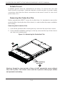
• In single rack installation, stabilizers should be attached to the rack.
• In multiple rack installations, the racks should be coupled together.
• Always make sure the rack is stable before extending a component from it.
• You should extend only one component at a time - extending two or more
simultaneously may cause the rack to become unstable.
Server Precautions
• Review the electrical and general safety precautions in Chapter 4.
• Determine the placement of each component in the rack before you install the
rails.
• Install the heaviest server components on the bottom of the rack fi rst, and then
work up.
• Use a regulating uninterruptible power supply (UPS) to protect the server from
power surges, voltage spikes and to keep your system operating in case of a
power failure.
• Allow the hot plug SATA drives and power supply modules to cool before
touching them.
• Always keep the rack's front door and all panels and components on the servers
closed when not servicing to maintain proper cooling.
Page is loading ...
Page is loading ...
Page is loading ...
Page is loading ...
Page is loading ...
Page is loading ...
Page is loading ...
Page is loading ...
Page is loading ...
Page is loading ...
Page is loading ...
Page is loading ...
Page is loading ...
Page is loading ...
Page is loading ...
Page is loading ...
Page is loading ...
Page is loading ...
Page is loading ...
Page is loading ...
Page is loading ...
Page is loading ...
Page is loading ...
Page is loading ...
Page is loading ...
Page is loading ...
Page is loading ...
Page is loading ...
Page is loading ...
Page is loading ...
Page is loading ...
Page is loading ...
Page is loading ...
Page is loading ...
Page is loading ...
Page is loading ...
Page is loading ...
Page is loading ...
Page is loading ...
Page is loading ...
Page is loading ...
Page is loading ...
Page is loading ...
Page is loading ...
Page is loading ...
Page is loading ...
Page is loading ...
Page is loading ...
Page is loading ...
Page is loading ...
Page is loading ...
Page is loading ...
Page is loading ...
Page is loading ...
Page is loading ...
Page is loading ...
Page is loading ...
Page is loading ...
Page is loading ...
Page is loading ...
Page is loading ...
Page is loading ...
Page is loading ...
Page is loading ...
Page is loading ...
Page is loading ...
Page is loading ...
Page is loading ...
Page is loading ...
Page is loading ...
Page is loading ...
Page is loading ...
Page is loading ...
Page is loading ...
Page is loading ...
Page is loading ...
Page is loading ...
Page is loading ...
Page is loading ...
Page is loading ...
Page is loading ...
Page is loading ...
Page is loading ...
Page is loading ...
Page is loading ...
Page is loading ...
Page is loading ...
Page is loading ...
Page is loading ...
Page is loading ...
Page is loading ...
Page is loading ...
Page is loading ...
Page is loading ...
Page is loading ...
Page is loading ...
Page is loading ...
Page is loading ...
Page is loading ...
Page is loading ...
Page is loading ...
Page is loading ...
Page is loading ...
Page is loading ...
Page is loading ...
Page is loading ...
Page is loading ...
Page is loading ...
Page is loading ...
Page is loading ...
-
 1
1
-
 2
2
-
 3
3
-
 4
4
-
 5
5
-
 6
6
-
 7
7
-
 8
8
-
 9
9
-
 10
10
-
 11
11
-
 12
12
-
 13
13
-
 14
14
-
 15
15
-
 16
16
-
 17
17
-
 18
18
-
 19
19
-
 20
20
-
 21
21
-
 22
22
-
 23
23
-
 24
24
-
 25
25
-
 26
26
-
 27
27
-
 28
28
-
 29
29
-
 30
30
-
 31
31
-
 32
32
-
 33
33
-
 34
34
-
 35
35
-
 36
36
-
 37
37
-
 38
38
-
 39
39
-
 40
40
-
 41
41
-
 42
42
-
 43
43
-
 44
44
-
 45
45
-
 46
46
-
 47
47
-
 48
48
-
 49
49
-
 50
50
-
 51
51
-
 52
52
-
 53
53
-
 54
54
-
 55
55
-
 56
56
-
 57
57
-
 58
58
-
 59
59
-
 60
60
-
 61
61
-
 62
62
-
 63
63
-
 64
64
-
 65
65
-
 66
66
-
 67
67
-
 68
68
-
 69
69
-
 70
70
-
 71
71
-
 72
72
-
 73
73
-
 74
74
-
 75
75
-
 76
76
-
 77
77
-
 78
78
-
 79
79
-
 80
80
-
 81
81
-
 82
82
-
 83
83
-
 84
84
-
 85
85
-
 86
86
-
 87
87
-
 88
88
-
 89
89
-
 90
90
-
 91
91
-
 92
92
-
 93
93
-
 94
94
-
 95
95
-
 96
96
-
 97
97
-
 98
98
-
 99
99
-
 100
100
-
 101
101
-
 102
102
-
 103
103
-
 104
104
-
 105
105
-
 106
106
-
 107
107
-
 108
108
-
 109
109
-
 110
110
-
 111
111
-
 112
112
-
 113
113
-
 114
114
-
 115
115
-
 116
116
-
 117
117
-
 118
118
-
 119
119
-
 120
120
-
 121
121
-
 122
122
-
 123
123
-
 124
124
-
 125
125
-
 126
126
-
 127
127
-
 128
128
-
 129
129
-
 130
130


Supermicro SuperServer 6026TT-HIBQRF User manual
- Category
- Server barebones
- Type
- User manual
- This manual is also suitable for
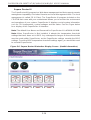
Ask a question and I''ll find the answer in the document
Finding information in a document is now easier with AI
Related papers
-
Supermicro SuperServer 5037MC-H86RF User manual
-
-
SUPER MICRO Computer CSE-827B-R1200B User manual
-
-
-
-
Supermicro 6026TT-D6IBQRF User manual
-
-
-
Other documents
-
Intel SR1670HV - Server System - 0 MB RAM Specification
-
 Supero SUPERSERVER 2027TR-D70RF+ User manual
-
 Supero 2U Twin3 SuperServer 2015TA-HTRF User manual
-
 Supero A+ SERVER 2022TG-HTRF User manual
-
SUPER MICRO Computer H8DCT-HLN4F User manual
-
 Premio DSS212S-U5-2U-12-BAY-3-5-HDD-12G-SAS-REDUNDANT-NODE-SINGLE-XEON-SP Installation guide
-
 Supero 2022TC-BIBQRF User manual
-
Gigabyte GS-R1271-RH System Installation Manual
-
-


