Supermicro SC743i-R760(B) User manual
- Category
- Computer cases
- Type
- User manual

USER’S MANUAL
Revision 1.3
SC743 Chassis
SC743TQ-865B-SQ SC743T-665B SC743T-R760(B)
SC743TQ-R760(B) SC743T-500B SC743i-665B
SC743S1-R760(B) SC743TQ-865(B) SC743i-500B
SC743i-R760(B) SC743S2-R760(B) SC743i-465B
SC743TQ-903B SC743AC-668B SC743AC-1200B-SQ

Chassis SC743 User's Manual
2
The information in this User’s Manual has been carefully reviewed and is believed to be accurate. The vendor assumes
no responsibility for any inaccuracies that may be contained in this document, and makes no commitment to update
or to keep current the information in this manual, or to notify any person or organization of the updates. Please Note:
For the most up-to-date version of this manual, please see our website at www.supermicro.com.
Super Micro Computer, Inc. ("Supermicro") reserves the right to make changes to the product described in this manual
at any time and without notice. This product, including software and documentation, is the property of Supermicro and/
or its licensors, and is supplied only under a license. Any use or reproduction of this product is not allowed, except
as expressly permitted by the terms of said license.
IN NO EVENT WILL Super Micro Computer, Inc. BE LIABLE FOR DIRECT, INDIRECT, SPECIAL, INCIDENTAL,
SPECULATIVE OR CONSEQUENTIAL DAMAGES ARISING FROM THE USE OR INABILITY TO USE THIS PRODUCT
OR DOCUMENTATION, EVEN IF ADVISED OF THE POSSIBILITY OF SUCH DAMAGES. IN PARTICULAR, SUPER
MICRO COMPUTER, INC. SHALL NOT HAVE LIABILITY FOR ANY HARDWARE, SOFTWARE, OR DATA STORED
OR USED WITH THE PRODUCT, INCLUDING THE COSTS OF REPAIRING, REPLACING, INTEGRATING,
INSTALLING OR RECOVERING SUCH HARDWARE, SOFTWARE, OR DATA.
Any disputes arising between manufacturer and customer shall be governed by the laws of Santa Clara County in the
State of California, USA. The State of California, County of Santa Clara shall be the exclusive venue for the resolution
of any such disputes. Supermicro's total liability for all claims will not exceed the price paid for the hardware product.
FCC Statement: This equipment has been tested and found to comply with the limits for a Class A digital device
pursuant to Part 15 of the FCC Rules. These limits are designed to provide reasonable protection against harmful
interference when the equipment is operated in a commercial environment. This equipment generates, uses, and can
radiate radio frequency energy and, if not installed and used in accordance with the manufacturer’s instruction manual,
may cause harmful interference with radio communications. Operation of this equipment in a residential area is likely
to cause harmful interference, in which case you will be required to correct the interference at your own expense.
California Best Management Practices Regulations for Perchlorate Materials: This Perchlorate warning applies only
to products containing CR (Manganese Dioxide) Lithium coin cells. “Perchlorate Material-special handling may apply.
See www.dtsc.ca.gov/hazardouswaste/perchlorate”.
WARNING: Handling of lead solder materials used in this product may expose you to lead, a
chemical known to the State of California to cause birth defects and other reproductive harm.
The products sold by Supermicro are not intended for and will not be used in life support systems, medical equipment,
nuclear facilities or systems, aircraft, aircraft devices, aircraft/emergency communication devices or other critical
systems whose failure to perform be reasonably expected to result in signicant injury or loss of life or catastrophic
property damage. Accordingly, Supermicro disclaims any and all liability, and should buyer use or sell such products
for use in such ultra-hazardous applications, it does so entirely at its own risk. Furthermore, buyer agrees to fully
indemnify, defend and hold Supermicro harmless for and against any and all claims, demands, actions, litigation, and
proceedings of any kind arising out of or related to such ultra-hazardous use or sale.
Manual Revision 1.3
Release Date: August 31, 2017
Unless you request and receive written permission from Super Micro Computer, Inc., you may not copy any part of this
document. Information in this document is subject to change without notice. Other products and companies referred
to herein are trademarks or registered trademarks of their respective companies or mark holders.
Copyright © 2017 by Super Micro Computer, Inc.
All rights reserved.
Printed in the United States of America

3
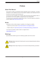
Preface
Preface
About this Manual
This manual is written for professional system integrators and PC technicians. It provides
information for the installation and use of the chassis. Installation and maintenance should
be performed by experienced technicians only.
This document lists compatible parts available when this document was published. Refer to
the Supermicro web site for updates on supported parts and congurations.
This manual may be periodically updated without notice. Check the Supermicro website for
possible updates.(http://www.supermicro.com).
Notes
Information on this and other chassis is available on the Supermicro website.
• Supermicro product manuals: http://www.supermicro.com/support/manuals/
• Product safety info: http://www.supermicro.com/about/policies/safety_information.cfm
If you have any questions, please contact our support team at:
Warnings
Special attention should be given to the following symbols used in this manual.
Warning! Indicates high voltage may be encountered when performing a procedure.
Warning! Indicates important information given to prevent equipment/property damage
or personal injury.

4
Chassis SC743 User's Manual
Contents
Chapter 1 Introduction
1.1 Overview ...............................................................................................................................7
1.2 Unpacking the System .........................................................................................................8
1.3 System Features ..................................................................................................................8
1.4 Chassis Features .................................................................................................................9
Control Panel ......................................................................................................................9
Front Features ...................................................................................................................10
Rear Features ...................................................................................................................11
1.5 Where to Get Replacement Components ..........................................................................12
1.6 Returning Merchandise for Service ....................................................................................12
Chapter 2 Rack Mount Installation
2.1 Overview .............................................................................................................................13
2.2 Preparing for Rack Mounting .............................................................................................13
Choosing a Setup Location ...............................................................................................13
Rack Precautions ..............................................................................................................13
Server Precautions ............................................................................................................14
Rack Mounting Considerations .........................................................................................14
Ambient Operating Temperature ....................................................................................14
Airow ............................................................................................................................14
Mechanical Loading .......................................................................................................14
Circuit Overloading ........................................................................................................15
Reliable Ground .............................................................................................................15
2.3 Chassis Preparation ...........................................................................................................16
2.4 Installing the Rails ..............................................................................................................17
Identifying the Rails .........................................................................................................17
Releasing the Inner Rails ..................................................................................................17
Installing the Inner Rails ...................................................................................................18
Assembling and Installing the Outer Rails ........................................................................19
2.5 Installing the Server into the Rack .....................................................................................20
Removing the Chassis from the Rack ..............................................................................21
2.6 Control Panel Orientation ...................................................................................................22

5
Preface
Chapter 3 Maintenance and Component Installation
3.1 Removing Power ................................................................................................................24
3.2 Accessing the System ........................................................................................................25
3.3 Chassis Components .........................................................................................................26
Storage Drives ..................................................................................................................26
Drive Indicators .............................................................................................................26
Installing the Standard 3.5" Drives ................................................................................27
Conguring the 5.25" Drive Bays ......................................................................................29
Additional Storage Drives in a Mobile Rack ..................................................................32
Installing Expansion Cards................................................................................................34
System Cooling .................................................................................................................35
Chassis Fans .................................................................................................................35
Air Shroud ......................................................................................................................36
Power Supply ....................................................................................................................37
465, 500, 665, 668, 865 and 1200 Watt Power Supplies .................................................37
Installing the Power Supply ...........................................................................................37
760 Watt Power Supply ....................................................................................................39
Installing the Power Supply ...........................................................................................39
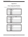
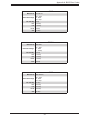
Appendix A Power Supply Specications
Appendix B Standardized Warning Statements for AC Systems
Appendix C BPN-SAS-743TQ Backplane Specications
Appendix D BPN-SAS3-743A Backplane Specications
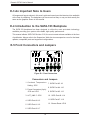
Appendix E SATA-743 Backplane Specications

6
Chassis SC743 User's Manual
Contacting Supermicro
Headquarters
Address: Super Micro Computer, Inc.
980 Rock Ave.
San Jose, CA 95131 U.S.A.
Tel: +1 (408) 503-8000
Fax: +1 (408) 503-8008
Email: [email protected] (General Information)
[email protected] (Technical Support)
Website: www.supermicro.com
Europe
Address: Super Micro Computer B.V.
Het Sterrenbeeld 28, 5215 ML
's-Hertogenbosch, The Netherlands
Tel: +31 (0) 73-6400390
Fax: +31 (0) 73-6416525
Email: [email protected] (General Information)
[email protected] (Technical Support)
[email protected] (Customer Support)
Website: www.supermicro.nl
Asia-Pacic
Address: Super Micro Computer, Inc.
3F, No. 150, Jian 1st Rd.
Zhonghe Dist., New Taipei City 235
Taiwan (R.O.C)
Tel: +886-(2) 8226-3990
Fax: +886-(2) 8226-3992
Email: [email protected]
Website: www.supermicro.com.tw

7
Chapter 1: Introduction
Chapter 1
Introduction
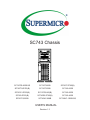
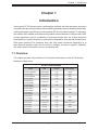
Supermicro's SC743 chassis series is optimized for the latest Intel Xeon processor and is also
compatible with previous generation Intel and AMD single/dual processor-based motherboards.
Utilizing redundant, high-efciency power supplies (95+%) and eight hot-swap 3.5" drive bays,
this chassis offers reliable performance with problem-free maintenance. Designed with 100%
cooling redundancy using a combination of high-performance fans, the chassis minimizes
the probability of system downtime or performance degradation from thermal-related issues.
With seven tool-less PCIe expansion slots, and 6-pin power connectors supporting up to
three high-end graphics cards, and it is quick to congure and easy to operate. Optionally,
this tower can be converted to mount in a standard rack.
1.1 Overview
This chapter provides a brief outline of the functions and features of the SC743 chassis.
Models are listed below.
SC743 Chassis Models
Model HDD I/O Slots Power Supply
SC743AC-1200B-SQ 8x SAS3/SATA 7x FF 1200W
SC743TQ-903B 8x SAS3/SATA 7x FF 903W
SC743TQ-865B-SQ 8x SAS/SATA 7x FF 865W
SC743TQ-865B 8x SAS/SATA 7x FF 865W
SC743TQ-R760 /
SC743TQ-R760B
8x SAS/SATA 7x FF 760W
SC743S2-R760 /
SC743S2-R760B
8x SCA Dual
Channel
7x FF 760W
SC743S1-R760 /
SC743S1-R760B
8x SCA 7x FF 760W
SC743T-R760 /
SC743T-R760B
8x SATA 7x FF 760W
SC743i-R760 /
SC743i-R760B
8x Fixed 7x FF 760W
SC743AC-668B 8x SAS3/SATA 7x FF 668W
SC743T-665B 8x SAS/SATA 7x FF 665W Super Quiet
SC743i-500B 8x Fixed 7x FF 500W
SC743T-500B 8x SATA 7x FF 500W
SC743i-465 /
SC743i-465B
8x Fixed 7x FF 465W Low Noise

8
Chassis SC743 User's Manual
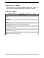
1.2 Unpacking the System
Inspect the box in which the chassis was shipped, and note if it was damaged. If any
equipment appears damaged, le a damage claim with the carrier who delivered it.
1.3 System Features
The following table provides you with an overview of the main features of the SC743.
System Features
Chassis
SC743
Drives Bays
Up to eight SAS3/SATA3 3.5" hot-swap drives, or optionally, 2.5" drives with converter
Cooling
Three 8-cm, 4-pin PWM mid-chassis fans; two 8-cm exhaust fans; one airow shroud
(-SQ models have two 8-cm fans and one 9-cm fan for super quiet performance)
Expansion Slots
Seven PCI-Express full-height slots
Form Factor
4U tower; optional rack mounting rails
Dimensions
(WxHxD) 17.3 x 7.0 x 38.2 in. (438 x 178 x 970 mm)

9
Chapter 1: Introduction
1.4 Chassis Features
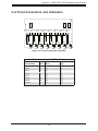
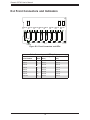
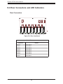
Control Panel
Power switches and status LEDs are located on the control panel on the front of the chassis.
Control Panel Features
Item Feature Description
1 Power Button
The main power button is used to apply or remove power from the power supply
to the server. Turning off system power with this button removes the main power
but maintains standby power.
2 Reset Button The reset button is used to reboot the system.
3 Power LED
Indicates power is being supplied to the system power supply. This LED should
normally be illuminated when the system is operating.
4 HDD LED Indicates hard drive activity when ashing.
5 NIC1 LED Indicates network activity on LAN port 1 when ashing.
6 NIC2 LED Indicates network activity on LAN port 2 when ashing.
7 Information LED See table below for details.
8 Power Fail LED
This LED ashes to indicate one of the redundant power supply modules has
failed. The ashing light should be accompanied by an audible warning.
9 USB0 Port USB 3.0 port
10 USB1 Port USB 3.0 port
Figure 1-1. Control Panel View
Information LED
Status Description
Continuously on and red
An overheat condition has occurred.
(This may be caused by cable congestion.)
Blinking red (1Hz) Fan failure, check for an inoperative fan.
Solid blue
Local UID has been activated. Use this function to
locate the server in a rackmount environment.
Blinking blue
Remote UID is on. Use this function to identify the
server from a remote location.
1
8
9
76543
2
10

10
Chassis SC743 User's Manual
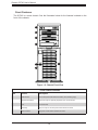
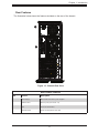
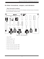
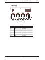
Front Features
The SC743 is a tower chassis. See the illustration below for the features included on the
front of the chassis.
Figure 1-2. Chassis Front View
Front Chassis Features
Item Feature Description
1 Control Panel Front control panel with LEDs and buttons (see preceding page)
2 Peripheral Drive Bays Three 5.25" bays for optional peripherals such as a DVD drive
3 Lock Front bezel lock
4 Drive Bays Eight 3.5" bays for hot-swap hard drives behind front bezel
5 Drive Indicators Eight pairs of LED status indicators for drives
3
1
2
2
4
2
5

11
Chapter 1: Introduction
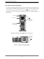
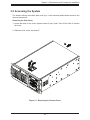
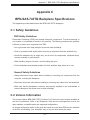
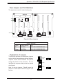
Rear Chassis Features
Item Feature Description
1 Power Supply Most models have P/S 2 power supplies
2 I/O Back Panel Rear I/O ports (see Section 4.3)
3 Fans Two 8-cm exhaust fans
4 Expansion Slots Seven PCI-E expansion card slots
Figure 1-3. Chassis Rear View
Rear Features
The illustration below shows the features included on the rear of the chassis.
1
4
3
2

12
Chassis SC743 User's Manual
1.5 Where to Get Replacement Components
If you need replacement parts for your system, to ensure the highest level of professional
service and technical support, purchase exclusively from our Supermicro Authorized
Distributors/System Integrators/Resellers. A list can be found at: http://www.supermicro.com.
Click the "Where to Buy" link.
1.6 Returning Merchandise for Service
A receipt or copy of your invoice marked with the date of purchase is required before any
warranty service will be rendered. You can obtain service by calling your vendor for a Returned
Merchandise Authorization (RMA) number. When returning to the manufacturer, the RMA
number should be prominently displayed on the outside of the shipping carton, and mailed
prepaid or hand-carried. Shipping and handling charges will be applied for all orders that
must be mailed when service is complete.
For faster service, RMA authorizations may be requested online (http://www.supermicro.com/
support/rma/).
Whenever possible, repack the chassis in the original Supermicro carton, using the original
packaging material. If these are no longer available, be sure to pack the chassis securely,
using packaging material to surround the chassis so that it does not shift within the carton
and become damaged during shipping.
This warranty only covers normal consumer use and does not cover damages incurred in
shipping or from failure due to the alteration, misuse, abuse or improper maintenance of
products.
During the warranty period, contact your distributor rst for any product problems.

13
Chapter 2 Rack Mount Installation
Chapter 2
Rack Mount Installation
2.1 Overview
This chapter provides instructions for preparing and mounting your chassis in a rack. By
default, the chassis is shipped congured as a tower. The tower top cover and bottom feet
must be removed to mount in a rack. Also, the control panel/drive module should be rotated
90 degrees.
Mounting rails are optional for this system. Be sure you have received the correct rail kit for
your server.
2.2 Preparing for Rack Mounting
Choosing a Setup Location
• The system should be situated in a clean, dust-free area that is well ventilated. Avoid areas
where heat, electrical noise and electromagnetic elds are generated.
• Leave at least 25 inches clearance in front of the rack to open the front door completely.
• Leave approximately 30 inches of clearance in the back of the rack to allow for sufcient
airow and access for servicing.
• It should be a restricted access location, such as a dedicated equipment room or a service
closet.
• This product is not suitable for use with visual display workplace devices acccording to §2
of the German Ordinance for Work with Visual Display Units.
Rack Precautions
• Ensure that the leveling jacks on the bottom of the rack are extended to the oor so that
the full weight of the rack rests on them.
• In single rack installations, stabilizers should be attached to the rack. In multiple rack
installations, the racks should be coupled together.
• Always make sure the rack is stable before extending a server or other component from
the rack.

Chassis SC743 User's Manual
14
• You should extend only one server or component at a time; extending two or more
simultaneously may cause the rack to become unstable.
• When initially installing the server to a rack, test that the rail locking tabs engage to prevent
the server from being overextended. Have a rack lift in place as a precaution in case the
test fails.
Server Precautions
• Review the electrical and general safety precautions in Appendix B.
• Determine the placement of each component in the rack before you install the rails.
• Install the heaviest server components at the bottom of the rack rst and then work your
way up.
• Use a regulating uninterruptible power supply (UPS) to protect the server from power
surges and voltage spikes and to keep your system operating in case of a power failure.
• Allow any drives and power supply modules to cool before touching them.
• When not servicing, always keep the front door of the rack and all covers/panels on the
servers closed to maintain proper cooling.
Rack Mounting Considerations
Ambient Operating Temperature
If installed in a closed or multi-unit rack assembly, the ambient operating temperature of
the rack environment may be greater than the room's ambient temperature. Therefore,
consideration should be given to installing the equipment in an environment compatible with
the manufacturer’s maximum rated ambient temperature (TMRA).
Airow
Equipment should be mounted into a rack so that the amount of airow required for safe
operation is not compromised.
Mechanical Loading
Equipment should be mounted into a rack so that a hazardous condition does not arise due
to uneven mechanical loading.

15
Chapter 2 Rack Mount Installation
Circuit Overloading
Consideration should be given to the connection of the equipment to the power supply circuitry
and the effect that any possible overloading of circuits might have on overcurrent protection
and power supply wiring. Appropriate consideration of equipment nameplate ratings should
be used when addressing this concern.
Reliable Ground
A reliable ground must be maintained at all times. To ensure this, the rack itself should be
grounded. Particular attention should be given to power supply connections other than the
direct connections to the branch circuit (i.e. the use of power strips, etc.).
To prevent bodily injury when mounting or servicing this unit in a rack, you must take
special precautions to ensure that the system remains stable. The following guidelines
are provided to ensure your safety:
• This unit should be mounted at the bottom of the rack if it is the only unit in the rack.
• When mounting this unit in a partially lled rack, load the rack from the bottom to the top
with the heaviest component at the bottom of the rack.
• If the rack is provided with stabilizing devices, install the stabilizers before mounting or
servicing the unit in the rack.
• Slide rail mounted equipment is not to be used as a shelf or a work space.

Chassis SC743 User's Manual
16
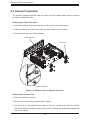
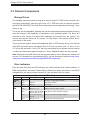
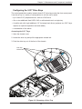
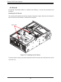
2.3 Chassis Preparation
The chassis is shipped with the tower top cover and feet installed. Both must be removed
for before installing the rails.
Removing the Tower Top Cover
1. Locate the chassis cover lock (blue lever) at the rear of the chassis cover.
2. Slide the chassis cover lock to the right and push chassis cover forward.
3. Lift the chassis top cover off the chassis.
Figure 2-1. Remove Feet and Chassis Top Cover
Removing the Chassis Feet
1. Place the chassis on its side.
2. Remove the screw holding a chassis foot in place.
3. The foot lock is a tab located in the center of the foot. It prevents the foot from sliding.
Using a at head screwdriver, gently lift the foot lock upward and slide the foot toward the
rear of the chassis.
Tower Top Cover
Chassis Feet
Chassis Cover Lock

17
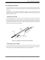
Chapter 2 Rack Mount Installation
Figure 2-2. Identifying the Sections of the Rack Rails
Inner rail
Outer rail
Rail brackets
2.4 Installing the Rails
There are a variety of rack units on the market, which may require a slightly different assembly
procedure. Do not use a two post "telco" type rack. This rail set ts a rack between 26" and
35.9" deep.
The following is a basic guideline for installing the system into a rack with the rack mounting
hardware provided. You should also refer to the installation instructions that came with the
specic rack you are using.
Identifying the Rails
The optional rackmount kit includes two rack rail assemblies, one for each side. Each of
these assemblies consist of several sections: an inner xed rail that secures to the chassis,
an outer rack rail that secures to the rack, a middle rail that slides within the outer rail, and
two brackets that attach the outer rail to the rack. The brackets are specic to the left and
right side, and front and back, and labeled.
Releasing the Inner Rails
The inner rails must be removed from the outer rails to install onto the chassis. To remove
the inner rail, pull it out as far as possible until it clicks to a stop. Depress the locking lever
on the inner rail next to the middle rail to pull the inner rail completely out.

Chassis SC743 User's Manual
18
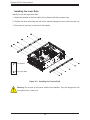
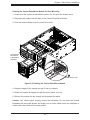
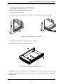
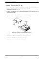
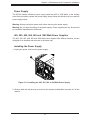
Figure 2-3. Installing the Chassis Rails
Installing the Inner Rails
Identify the left and right inner rails.
1. Attach the handles to the front sides of the chassis with three screws each.
2. Position the inner rails along the side of the chassis making sure the screw holes line up.
3. Screw the rail securely to the side of the chassis.
Warning: Do not pick up the server with the front handles. They are designed to pull
the system from a rack only.
Screw for Inner Rails
Screw for Handles

19
Chapter 2 Rack Mount Installation
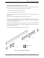
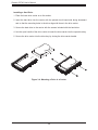
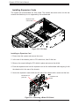
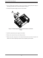
Figure 2-4. Assembling the Outer Rails
Assembling and Installing the Outer Rails
Each outer rail comes in three sections that require assembly before mounting onto the rack.
1. Find the outer rail mounting brackets in the chassis accessory box.
• A pair of long brackets for the rear of each rail
• A pair of short brackets for the front of each rail
Note that the brackets are labeled as to front, rear, and up. They are specic for the left
and right rails.
2. Secure the front (short) bracket onto the outer rail with M5 screws.
3. Mount the rear (long) bracket onto the outer rail at the approximate position to t your rack.
Use two or three M5 screws into holes that are convenient. Leave the screws just loose
enough that the bracket can slide.
4. Install the outer rail assembly onto your rack. Adjust the outer rail to the exact depth of the
rack by sliding the rear bracket. Then use screws and fasteners to secure the outer rail to
the front and rear rack posts.
5. Further tighten the screws holding the rear bracket to the rail.
4
3
2
4
Screw for Outer Rail
Brackets

Chassis SC743 User's Manual
20
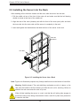
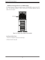
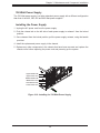
Note: Figure is for illustrative purposes only. Always install servers to the bottom of a rack rst.
Figure 2-5. Installing the Server into a Rack
2.5 Installing the Server into the Rack
After attaching rails to both the chassis and the rack, slide the server into the rack.
1. Pull the middle rail out of the front of the outer rail and make sure that the ball bearing
shuttle is locked at the front of the middle rail.
2. Align the rear of the inner (chassis) rails with the front of the outer (rack) rails and slide
the inner rails into the outer rails until the server is completely in the rack.
3. Insert and tighten the thumbscrews that hold the front of the server to the rack.
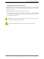
When initially installing the server to a rack, test that the rail locking tabs engage to
prevent the server from being overextended. Have a rack lift in place as a precaution
in case the test fails.
Warning: Stability hazard. The rack stabilizing mechanism must be in place, or the
rack must be bolted to the oor before you slide the unit out for servicing. Failure to
stabilize the rack can cause the rack to tip over.
Inner Rails
Outer Rail
Assemblies
Page is loading ...
Page is loading ...
Page is loading ...
Page is loading ...
Page is loading ...
Page is loading ...
Page is loading ...
Page is loading ...
Page is loading ...
Page is loading ...
Page is loading ...
Page is loading ...
Page is loading ...
Page is loading ...
Page is loading ...
Page is loading ...
Page is loading ...
Page is loading ...
Page is loading ...
Page is loading ...
Page is loading ...
Page is loading ...
Page is loading ...
Page is loading ...
Page is loading ...
Page is loading ...
Page is loading ...
Page is loading ...
Page is loading ...
Page is loading ...
Page is loading ...
Page is loading ...
Page is loading ...
Page is loading ...
Page is loading ...
Page is loading ...
Page is loading ...
Page is loading ...
Page is loading ...
Page is loading ...
Page is loading ...
Page is loading ...
Page is loading ...
Page is loading ...
Page is loading ...
Page is loading ...
Page is loading ...
Page is loading ...
Page is loading ...
Page is loading ...
Page is loading ...
Page is loading ...
Page is loading ...
Page is loading ...
Page is loading ...
Page is loading ...
Page is loading ...
Page is loading ...
Page is loading ...
Page is loading ...
Page is loading ...
-
 1
1
-
 2
2
-
 3
3
-
 4
4
-
 5
5
-
 6
6
-
 7
7
-
 8
8
-
 9
9
-
 10
10
-
 11
11
-
 12
12
-
 13
13
-
 14
14
-
 15
15
-
 16
16
-
 17
17
-
 18
18
-
 19
19
-
 20
20
-
 21
21
-
 22
22
-
 23
23
-
 24
24
-
 25
25
-
 26
26
-
 27
27
-
 28
28
-
 29
29
-
 30
30
-
 31
31
-
 32
32
-
 33
33
-
 34
34
-
 35
35
-
 36
36
-
 37
37
-
 38
38
-
 39
39
-
 40
40
-
 41
41
-
 42
42
-
 43
43
-
 44
44
-
 45
45
-
 46
46
-
 47
47
-
 48
48
-
 49
49
-
 50
50
-
 51
51
-
 52
52
-
 53
53
-
 54
54
-
 55
55
-
 56
56
-
 57
57
-
 58
58
-
 59
59
-
 60
60
-
 61
61
-
 62
62
-
 63
63
-
 64
64
-
 65
65
-
 66
66
-
 67
67
-
 68
68
-
 69
69
-
 70
70
-
 71
71
-
 72
72
-
 73
73
-
 74
74
-
 75
75
-
 76
76
-
 77
77
-
 78
78
-
 79
79
-
 80
80
-
 81
81


Supermicro SC743i-R760(B) User manual
- Category
- Computer cases
- Type
- User manual
Ask a question and I''ll find the answer in the document
Finding information in a document is now easier with AI
Related papers
-
SUPER MICRO Computer FAN0103L4 User manual
-
Supermicro SC213XAC-R1K05LP User manual
-
-
-
-
-
-
Supermicro SC513BTQC-350WB User manual
-
-