Page is loading ...

COPYRIGHT © JULY, 2003 BY GRIZZLY INDUSTRIAL, INC.
WARNING: NO PORTION OF THIS MANUAL MAY BE REPRODUCED IN ANY SHAPE
OR FORM WITHOUT THE WRITTEN APPROVAL OF GRIZZLY INDUSTRIAL, INC.
#505203624 PRINTED IN JAPAN
ONLINE MANUAL DISCLAIMER
THE INFORMATION IN THIS MANUAL REPRESENTS THE CONFIGURATION OF THE MACHINE AS IT IS CURRENTLY BEING SHIPPED. THE MACHINE
CONFIGURATION CAN CHANGE AS PRODUCT IMPROVEMENTS ARE INCORPORATED. IF YOU OWN AN EARLIER VERSION OF THE MACHINE, THIS
MANUAL MAY NOT EXACTLY DEPICT YOUR MACHINE . CONTACT CUSTOMER SERVICE IF YOU HAVE ANY QUESTIONS ABOUT DIFFERENCES. PRE-
VIOUS VERSIONS ARE NOT AVAILABLE ONLINE.
ELECTRIC GUITAR
MODEL H3123
INSTRUCTION MANUAL

WARNING
Some dust created by power sanding, sawing, grind-
ing, drilling, and other construction activities contains
chemicals known to the State of California to cause
cancer, birth defects or other reproductive harm.
Some examples of these chemicals are:
• Lead from lead-based paints.
• Crystalline silica from bricks, cement, and
other masonry products.
• Arsenic and chromium from chemically treated
lumber.
Your risk from these exposures varies, depending on
how often you do this type of work. To reduce your
exposure to these chemicals: work in a well ventilated
area, and work with approved safety equipment, such
as those dust masks that are specially designed to fil-
ter out microscopic particles.

SECTION 1: SAFETY........................................................................................................................2
SECTION 2: INTRODUCTION ..........................................................................................................3
SECTION 3: PARTS INVENTORY....................................................................................................4
SECTION 4: SANDING/FINISHING ..................................................................................................8
Supplies/Tools ............................................................................................................................8
Guitar Body ................................................................................................................................8
Neck ............................................................................................................................................9
Masking Tape Areas ..................................................................................................................9
Painting/Finishing......................................................................................................................10
SECTION 5: HARDWARE ..............................................................................................................11
Tuning Machines ......................................................................................................................11
Neck to Body ............................................................................................................................11
Pick Guard ................................................................................................................................12
Tremolo Bridge..........................................................................................................................13
Strap Button ..............................................................................................................................15
Audio Jack ................................................................................................................................16
Winding Strings ........................................................................................................................16
String Retainers ........................................................................................................................17
Mounting Back Plate ................................................................................................................18
Mounting Pick Guard ................................................................................................................18
SECTION 6: FINAL SET UP ..........................................................................................................19
Neck Adjustment ......................................................................................................................19
String Height ............................................................................................................................19
Pick Up Height ..........................................................................................................................21
Tremolo Arm ............................................................................................................................22
Tuning ......................................................................................................................................22
SECTION 7: REFERENCE INFO ....................................................................................................24
General......................................................................................................................................24
Aftermarket Accessories ..........................................................................................................24
Warranty & Returns ..................................................................................................................26
TABLE OF CONTENTS

-2-
H3123 Electric Guitar Kit
SECTION 1: SAFETY
These instructions assume that you are intimately familiar with the safe operation and use of
woodworking machinery and woodworking tools, and understand the techniques used to repro-
duce this project. If you do not qualify for both of these criteria, STOP building this project for
your own safety. Read and understand the owners manual for the machinery you intend to use,
take a woodworking class or visit your local library for more information. Woodworking machinery
and tools are inherently dangerous because they use sharp edges that can and will cause serious
personal injury including amputation and death. Do not underestimate the ability of these tools and
machinery to cause injury. Never operate any tool without all guards in place and always wear
approved safety glasses. For your own safety, please heed this warning.
Always wear safety glasses or goggles when operating equipment. Everyday glasses or
reading glasses are not safety glasses. Be certain the safety glasses you wear meet the
appropriate standards of the American National Standards Institute (ANSI).
Because there are various ways to cut and join wood, you can make substitutions for the meth-
ods stated in this plan. We try to suggest the easiest methods possible. However, only you know
your skills with each piece of machinery. Never compromise your safety by using a cutting method
with which you are not comfortable. Instead, find an alternative approach that will yield the same
result.

H3123 Electric Guitar Kit -3-
We are proud to offer the Model H3123 Electric
Guitar Kit. This kit is part of a growing Grizzly
family of fine woodworking products. When
assembled according to the guidelines set forth in
this manual, you can expect years of enjoyment
from this guitar.
We are pleased to provide this manual with the
Model H3123. It was written to guide you through
assembly, review safety considerations, and
cover general information. It represents our effort
to produce the best documentation possible.
If you have any comments regarding this manual,
please write to us at the address below:
Grizzly Industrial, Inc.
C
/
O Technical Documentation
P.O. Box 2069
Bellingham, WA 98227-2069
Most importantly, we stand behind our products.
If you have any questions or parts requests,
please call or write us at the location listed below.
Grizzly Industrial, Inc.
1203 Lycoming Mall Circle
Muncy, PA 17756
Phone: (570) 546-9663
Fax: (800) 438-5901
E-Mail: [email protected]
Web Site: http://www.grizzly.com
The specifications, drawings, and photographs
illustrated in this manual represent the Model
H3123 as supplied when the manual was pre-
pared. However, owing to Grizzly’s policy of con-
tinuous improvement, changes may be made at
any time with no obligation on the part of Grizzly.
For your convenience, we always keep current
Grizzly manuals available on our website at
www.grizzly.com
. Any updates to products will be
reflected in these manuals as soon as they are
complete. Visit our site often to check for the lat-
est updates to this manual!
SECTION 2: INTRODUCTION

-4-
H3123 Electric Guitar Kit
SECTION 3: PARTS INVENTORY
Bag 1 QTY
1. Silver Neckplate 1
2. Black Neckplate Setter 1
3. Audio Output Jack 1
Boxed Components QTY
1. Guitar Body 1
2. Guitar Neck 1
3. Pickguard 1
Figure 1. Boxed components.
Figure 2. Bag 1 components.
1
2
3
1
2
3

H3123 Electric Guitar Kit -5-
Bag 3 QTY
1. String Set 1
2. String Guides 2
3. String Guide Risers 2
4. #2 x
3
⁄8" Pan Head Screw 2
Bag 2 QTY
1. Tuning Machines 6
2. Bushings 6
3. #1 x
5
⁄32" Pan Head Screw 12
Figure 3. Bag 2 components. Figure 4. Bag 3 components.
1
2
3
1
2
3
4

-6-
H3123 Electric Guitar Kit
Bag 5 QTY
Audio Patch Cable 1
Bag 4 QTY
Tremolo Bridge 1
Figure 5. Tremolo bridge. Figure 6. Audio patch cable.

H3123 Electric Guitar Kit -7-
Bag 7 QTY
1. Springs 4
2. Spring Hanger 1
3. Strap Buttons 2
4. String Nut 1
5. #4 x
3
⁄8" Flat Head Screws 20
6. #10 x 1
3
⁄4" Flat Head Screws 4
7. #7 x 1
1
⁄2" Flat Head Screws 2
8. #4 1 " Pan Head Screws 6
9. Back Plate 1
Bag 6 QTY
1. Tremolo Arm 1
2. 5mm Allen Wrench 1
3. 1.5mm Allen Wrench 1
Figure 7. Bag 6 components. Figure 8. Bag 7 components.
1
2
3
1
2
3
45
6
7
8
9

-8-
H3123 Electric Guitar Kit
The majority of the wooden components in this kit
are fully machined from the factory and are ready
for assembly. A small amount of drilling, sanding
and light machining will need to be performed to
complete the guitar.
Recommended Tools & Supplies:
—Phillips Screwdriver
—Needle-Nose Pliers
—Electric Drill
—Drill Bit Set
—Soldering Iron & Solder
—#180, #240, and #320 Aluminum-Oxide
Sanding Paper
—Sanding Block
—Masking Tape
—Painting/Finishing Supplies
—Coat Hanger
—C-Clamp
—5MM Allen Wrench (Supplied)
—1.5MM Allen Wrench (Supplied)
—Tack Cloth
—Coping, Jig, or Scroll Saw (Optional)
The guitar body has been machined and rough
sanded at the factory; however, no finish has
been applied.
To sand the guitar body:
1. Wear an ANSI-approved dust mask and
safety glasses when sanding wood!
2. Using either an electric palm sander or a
sanding block, sand the guitar body
(EXCEPT the guitar neck notch and other
recessed areas) with #180 grit aluminum-
oxide sanding paper until there is a consis-
tent scratch pattern on the entire surface.
3. Sand the guitar body with a #240 grit sand-
ing paper until there is a consistent scratch
pattern on the entire surface.
4. Sand the guitar body with a #320 grit sand-
ing paper until there is a consistent scratch
pattern on the entire surface.
5. Wipe the guitar body with a damp cloth.
Wiping the workpiece with a damp cloth
before the final sanding helps to “raise” the
wood grain; thus, allowing the “raised” grain
to be sanded smooth.
6. Once the guitar body is dry, repeat step 4.
7. Wipe the guitar body with a tack cloth to
remove all remaining sanding dust.
Guitar BodySupplies/Tools
SECTION 4: SANDING/FINISHING

H3123 Electric Guitar Kit -9-
Like the guitar body, the guitar neck is mostly
complete from the factory; however, the neck
headstock can be customized to reflect personal
taste. Additional cutting, inlay, or design work can
give an otherwise ordinary guitar that custom look
that sets it apart from others! Note—Take your
time with this sub-section and consider testing
ideas in scrap wood before performing the work
on the actual headstock.
To sand the guitar neck:
1. Wear an ANSI-approved dust mask and
safety glasses when sanding wood!
2. Perform any custom cutting, inlay, or design
work to the neck headstock.
3. Using the sanding technique described in the
previous sub-section, sand the entire guitar
neck, EXCEPT for the fingerboard surface
(Figure 9). Note—Sanding the fingerboard
will affect the playability of the guitar, and
could lead to unrepairable damage.
Neck
In preparation for the finish coating, the fol-
lowing parts of the guitar (Figures 9 & 10)
need to be covered with masking tape:
• Neck Pocket
• Fingerboard
• Truss Rod Cut-Out
Masking Tape Areas
Figure 9. Neck pocket and fingerboard areas.
Use a small stick of wood to carefully press all the
masking tape edges securely to the guitar pieces.
The finish coat can seep under these edges,
especially near corners, uneven edges, and
where the frets meet the fingerboard. Note—
Failure to correctly mask off these areas could
result in unrepairable damage to the guitar.
Figure 10. Truss rod area (hardware should not
be installed at this time).

-10-
H3123 Electric Guitar Kit
Painting and finishing supplies are not supplied
with the guitar kit. Note—The guitar body is made
from alder wood and the neck from maple wood.
Clear finishes such as lacquer look exceptionally
stunning and glossy on these nice types of wood.
Painting/Finishing Tips:
• Always work in a well ventilated area
when using finishing materials.
• Wear an ANSI-approved respirator mask
and safety glasses when using finishing
materials!
• Fabricate hooks from shirt hangers to sus-
pend the guitar components during the fin-
ishing process.
• Several thinner coats usually produce a nicer
finish than one heavy coat. Note—Always
follow the finish manufacturer’s instructions.
• Dust particles suspended in the air will settle
on wet finishes, resulting in less than satis-
factory results. To avoid this problem:
1. Leave the room where the finishing will
take place completely undisturbed for 24
hours prior to applying the finish.
2. Have the guitar components positioned
for the finish application upon entering the
room.
3. Avoid making unnecessary movements
upon entering the finish room.
4. Apply the finish to the desired guitar parts
and immediately leave the finish room.
5. DO NOT return to the room until the spec-
ified drying time has elapsed.
• Always follow the finish manufacturer’s
instructions.
Painting/Finishing

H3123 Electric Guitar Kit -11-
Tuning Machines
SECTION 5: HARDWARE
Each tuning machine consists of the machine
head, a bushing, and two wood screws.
To install the tuning machines:
1. Slide each of the six bushings into the pre-
drilled holes on the headstock. Note—Make
sure the bushings are slid into the pre-drilled
holes through the front face of the headstock.
2. Slide each machine head through the bush-
ings from the back face of the headstock.
3. Align the machine heads and secure their
position on the headstock with masking tape.
4. Using a
3
⁄32" drill bit, drill
3
⁄8" deep holes
straight through the two holes in the machine
heads. Note—Drilling the holes deeper than
3
⁄8" could result in drilling out through the front
face of the headstock.
5. Secure the machine heads to the guitar
headstock with the included twelve
1
⁄2" wood
screws (Figure 11).
Neck to Body
To attach the neck to the guitar body:
1. Remove the masking tape from the neck
pocket.
2. Place the neck into the neck pocket (Figure
12). Note—Make sure the neck is fully seat-
ed into the neck pocket. No gaps should be
visible between the neck and the body.
3. Hold the neck to the body with a C-clamp.
— If the back side of the fingerboard does
not sit flush against the guitar body, then
the neck pocket needs to be deepend or
material needs to be removed from the
back of the neck. A router is the easiest
tool for performing this task; however, a
sharp chisel will also work. Note—Use a
pattern cutting router bit when removing
material from the neck pocket. Use a
straight cutting router bit when removing
material from the back of the neck.
Figure 12. The neck should fit snugly into the
neck pocket.
Figure 11. Correctly positioned tuning
machines.

-12-
H3123 Electric Guitar Kit
5. Place the black neckplate setter and the sil-
ver neckplate over the holes on the back of
the guitar body.
6. Secure the neckplate assembly, the guitar
body, and the neck together with the includ-
ed 1
3
⁄4" wood screws (Figure 14). DO NOT
use glue.
4. Using a
5
⁄32" drill bit, drill 1
3
⁄4" deep holes
straight through the four holes in the back of
the body (Figure 13). Note—Drilling the
holes deeper than 1
3
⁄4" could result in drilling
out through the fingerboard.
Figure 13. Drilling the screw holes.
Figure 14. Correctly attached neck.
Pick Guard
To attach the pick guard to the guitar body:
1. Push one white and one black wire through
the hole shown in Figure 15.
2. Push the remaining black wire through the
hole shown in Figure 16.
Figure 15. Pick guard wires.
Figure 16. Pick guard wire.

H3123 Electric Guitar Kit -13-
3. Secure the wires with masking tape so they
do not fall back out through the holes.
4. Align the pick guard on the guitar body as
shown in Figure 17. Pay special attention to
the neck cutout alignment on the body.
5. Secure the position of the pick guard to the
body with masking tape.
6. DO NOT drill the screws at this time! Final
adjustments need to be made after installing
and winding the strings.
Figure 17. Pick guard alignment.
Tremolo Bridge
To attach the tremolo bridge to the guitar
body:
1. Place the tremolo bridge in the cut-out shown
in Figure 18.
2. The tremolo bridge is correctly positioned
when the distance between the center of the
12th fret and the front edge of the tremolo
bridge are precisely 12
7
⁄16" apart (Figure 19).
Figure 18. Tremolo bridge placement.
Figure 19. Correct distance between the 12th
fret and the tremolo bridge.
12
7
⁄16"
12th Fret

-14-
H3123 Electric Guitar Kit
3. Attach pieces of sewing thread to the 1st and
the 6th machine head and tape the opposite
ends to the edges of the tremolo bridge.
4. Adjust the tremolo bridge so there is an
equal amount of space between the finger-
board edges and the threads (Figure 20).
5. When all adjustments are correct, secure the
position of the tremolo bridge to the guitar
body with masking tape.
6. Using a
3
⁄
32" drill bit, drill
1
⁄
2" deep holes
straight through the six holes in the tremolo
bridge (Figure 21). Note—Drilling the holes
deeper than
1
⁄2" could result in drilling out
through the back of the guitar body.
Figure 20. Checking neck alignment with
tremolo bridge.
Figure 21. Drilling the bridge mounting holes.
Equal Space
Attach Threads Here
Attach Threads Here
7. Secure the tremolo bridge to the guitar body
with the included six
1
⁄2" wood screws.
8. Flip the guitar body over and place the spring
hanger in the cavity as shown in Figure 22.
9. Secure the position of the spring hanger to
the guitar body with masking tape.
10. Using a
1
⁄8" drill bit, drill 1
1
⁄2" deep holes
straight through the two holes in the spring
hanger (Figure 23). Note—DO NOT drill the
holes deeper than 1
1
⁄2".
Figure 22. Spring hanger placement.
Figure 23. Drilling the spring hanger
mounting holes.

H3123 Electric Guitar Kit -15-
11. Solder the black wire to the spring hanger.
12. Secure the spring hanger to the guitar body
with the included two 1
1
⁄2" wood screws.
13. Hang the three springs from the spring hang-
er to the tremolo bridge as shown in Figure
24.
Figure 24. Correct spring placement.
Strap Button
The strap buttons are positioned on the guitar as
shown in Figure 25.
To attach the strap buttons to the guitar body:
1. Using a
3
⁄32" drill bit, drill
3
⁄4" deep holes at
each of the mounting locations.
2. Secure the strap buttons to the guitar body
with the included two
3
⁄
4" wood screws.
Figure 25. Strap buttons.

-16-
H3123 Electric Guitar Kit
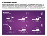
Winding Strings
The correct position of the guitar strings is shown
in Figure 27. The thin High E string is called the
"1st" string and the thick Low E string is called the
"6th" string.
To install the guitar strings:
1. Slide the 1st guitar string through the corre-
sponding hole in the back plate (Figure 28).
Figure 28. 1st string installation hole.
D
E
E
A
D
G
B
6
1
5
4
3
2
Figure 27. Correct string locations.
Audio Jack
To attach the audio jack to the guitar body:
1. Solder the wires shown in Figure 26 to the
tabs on the audio jack.
2. Turn the audio jack over and insert it in the
cavity on the guitar body.
3. Secure the position of the audio jack to the
guitar body with masking tape.
4. Using a
3
⁄
32" drill bit, drill
1
⁄
2" deep holes
straight through the two holes in the audio
jack. Note—Drilling the holes deeper than
1
⁄2"
could result in drilling out through the back of
the guitar body.
5. Secure the audio jack to the guitar body with
the included two
1
⁄
2" wood screws.
Figure 26. Soldered audio wire.

H3123 Electric Guitar Kit -17-
2. Guide the string over the string saddle on the
tremolo bridge, over the string nut, and
through the string hole in the corresponding
machine head.
3. Allow only enough slack in the string for 2-3
rotations around the machine head. Note—If
too much slack is allowed, then the string
could wind off the machine head after many
successive rotations. If not enough slack is
allowed, then the string may not hold the
winding tension.
4. Bend the string at a right angle across the
edge of the machine head.
5. Rotate the tuning machine until the string just
begins to hold the winding tension. Note—
DO NOT tighten the strings beyond the initial
tensioning at this time. Final tensioning
should be completed during the string tuning
process.
6. Use wire cutters to cut off the excess string.
7. Repeat the above process for the remaining
strings.
Figure 29. String retainer locations.
String Retainers
The short string retainer mounts between the 1st
and 2nd strings and the taller spring retainer
mounts between the 3rd and 4th strings (Figure
29).
To install the string retainers:
1. Secure the position of the string retainers to
the headstock with masking tape.
2. Using a
1
⁄16" drill bit, drill
1
⁄2" deep holes
straight through the holes in the string retain-
ers. Note—Drilling the holes deeper than
1
⁄2"
could result in drilling out through the front
face of the headstock.
3. Secure the string retainers to the guitar with
the included two
1
⁄2" wood screws.
Tall Retainer
Short Retainer

-18-
H3123 Electric Guitar Kit
Mounting Pick
Guard
To secure the pick guard to the guitar body:
1. Position the pick guard so the 1st string is
centered over the corresponding round metal
pick-up peg as shown in Figure 30.
2. Secure the position of the pick guard to the
guitar body with masking tape.
3. Using a
3
⁄32" drill bit, drill
1
⁄2" deep holes
straight through the eleven holes in the pick
guard. Note—Drilling the holes deeper than
1
⁄2" could result in drilling out through the
back of the guitar body.
4. Secure the pick guard to the guitar body with
the included eleven
1
⁄2" wood screws.
Figure 31. Mounting the back plate.
Figure 30. Pick guard mounting location.
Mounting Back Plate
Once mounted, the six holes in the back plate
need to align with the six holes in the tremolo
bridge. This will simplify the string installation and
removal process.
To mount the back plate to the guitar body:
1. Position the back plate over the cavity in the
back of the guitar body as shown in Figure
31.
2. Secure the position of the back plate to the
guitar body with masking tape.
3. Using a
3
⁄32" drill bit, drill
1
⁄2" deep holes
straight through the six holes in the back
plate. Note—Drilling the holes deeper than
1
⁄2" could result in drilling out through the front
of the guitar body.
4. Secure the back plate to the guitar body with
the included six
1
⁄2" wood screws.
/