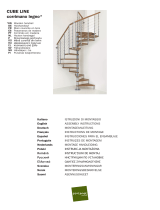
K35028

Arke K35028, K35001, K35012, K35017, K35021, K35023, K35025 Installation guide

  • Hello! I am an AI chatbot trained to assist you with the Arke K35028 Installation guide. I’ve already reviewed the document and can help you find the information you need or explain it in simple terms. Just ask your questions, and providing more details will help me assist you more effectively!
ATTENTION: insert the at washers C20 with the knurled surface towards the support ange.
ATENCIÓN: introducir la arandela C20 con la parte dentada hacia el lado del soporte.
KOMPACT
English
In order to proceed with the assembly, unpack all stair components and lay them out on a sufciently large surface.
Check all components for quantity, comparing with the list in TAB.1 (A = Code, B = Quantity).
In the packing box you will nd a DVD showing the assembly. We suggest watching it before proceeding with the
assembly.
For customers in the USA there is a customer assistance number 1-888 STAIRKT, which you can telephone in case
of problems.
Assembly
Measure carefully the oor-to-oor height (H) (g. 2).1.
Calculate the height of the Rise: 2.
a) deduct 20,5 cm (8 1/8”) (height of the rst rise) from the oor-to-oor height (H);
b) divide the result by the number of rises - 1 (divide by the number of treads, as the last rise is given by the
distance between the last tread and the landing oor).
Example (g. 2): with a oor-to-oor height of 263 cm (8’ 7 1/2”) and a staircase with 13 rises (i.e. with 12
treads): (263 – 20.5 / 13 – 1) (8’ 71/2” – 8 1/8” / 13 – 1) = 20.21 cm (8”).
Measure carefully the ceiling opening (C) (g. 2).3.
Calculate the measure of the Going (P): 4.
with the version of the staircase L=74 (2' 5
1/8”) (railing included) as in g. 2A the calculation is the following:
a) Deduct from the measure (C) of the ceiling opening the following steady measures:
1) 29 cm (11
3/8”) = depth of the last tread; 2) 69 cm (2’ 3 1/8”) = angle treads; 3) 1 cm (3/8”) = distance from
the wall.
b) Divide the result by the number of the remaining treads.
Example: with a ceiling opening measure of 231 (7' 7") cm and a staircase as in g. 2A, the calculation is the
following:
231 – 29 – 69 – 1 / 6 (7’ 7” – 113/8” – 2’ 31/8” – 3/8”/ 6) = 22 cm (8 5/8”) ( = measure of the going).
With the version of the staircase L=89 (2’ 11”) (railing included) as in g. 2B the calculation is the following:
a) Deduct from the measure (C) of the ceiling opening the following steady measures:
1) 33 cm (2’) = depth of the last tread; 2) 84 cm (2’9
1/2”) = angle treads; 3) 1 cm (3/8”) = distance from the
wall.
b) Divide the result by the number of the remaining treads.
Example: with a ceiling opening measure of 262 cm (8’7
1/8”) and a staircase as in g. 2B, the calculation is
the following:
262 – 33 – 84 – 1 / 6 (8’7
1/8” – 2’ – 2’9 1/8” – 3/8”/ 6 ) = 24 cm (9 1/2”) ( = measure of the going).
To determine easily the drilling point on the ceiling, you can t with the crew C53, the tread L25 onto the support 5.
N20 without tightening it denitively. In this manner it will be easy to sign the drilling points in line with the holes
in the plate of the nal support. Drill with bit Ø 18 mm (
22/32”) (g. 4) (g. 5). Tighten the nal support N20 on
the ceiling with the articles C48 checking the horizontal line of the stair.
Prepare the tie-rods C22 inserting the at washers C20 with the knurled surface towards the support ange and 6.
the nuts B99. Fit the elements N24 to the supports N21, N22 (g. 3). Insert, without tightening, the screws
B07, B06 and B23. Insert the tubes C21 into the internal part of the elements N24; the tie-rods C22; the at
washers C20 with the knurled surface towards the support ange and the nuts B99. Set the measure of the
going (P): for the straight treads the measure (P) is like calculated before (see point 4). For the angle treads the
going has a measure (P) of:
20 cm (7 7/8”) (g. 2A) for the version with the tread width (railing included) L=74 (2' 5 1/8”) .
24 cm (9 1/2”) (g. 2B) for the version with the tread width (railing included) L=89 (2’ 11”).
Fasten denitively the crews B07, B06 and B23. Proceed with the assembly of all the supports N21. Screw the
tube with the threaded tie-rod N25 to the support 2nd rise N22 until the end.
Insert the articles C13 and B02 into the elements F23. Fit the elements F23 with the articles C57 on level with 7.
the fore edge of the treads L25 upside down (on the side with the holes). Drill with bit Ø 4.5 mm (11/64”) to a
depth of 30 mm (11/8”) (g. 1) (g. 7).
Fit the tread L25 to the support N20 with the screws C53. Check the horizontal line of the tread and tighten 8.
denitively the articles C48. Put on the article D34 to cover the bracket with the help of the elements B12 and
C62, drilling with bit Ø 8 mm (5/16”) (g. 4) (g. 5).
Fit an intermediate support N21 into the nal support N20. Fasten it below by means of a self-blocking clamp 9.
before tightening. Assemble the tread by using the screws C53. (As you proceed with the assembly of supports
and treads, it is necessary to prop-up the supports with a mechanical steel prop, so that the ceiling will not have
to bear too much weight). It is necessary to put a piece of wood under every 4 to 5 supports and it is strictly
forbidden, for safety reasons, to get on the stair before having xed it to the oor (point 13) and strengthen
KOMPACT
it (point 14). Adjust the height of the rise that you have calculated in point 2; check the horizontal position of
the tread and the alignment with the tread previous tread. Tighten nally the pieces B99 by both side of the
support, in order to avoid that the tread is to be modied in its trim (horizontality and verticality) . Proceed in the
same way with the assembly of the remaining intermediate supports N21. On the angle treads (see g. 8) it is
necessary to carry out the drillings for connection with the supporting element, according to the chosen winding
direction (drill with drilling bit Ø 8,5 mm (21/64”) for a depth of 30 mm (1 1/8”) ).
(see g. 9) – Fit the elements F23 onto the internal side of the angle treads L26, L27, L28 by using the 10.
elements C57 (drill with drilling bit Ø 4.5 mm (11/64”) for a depth of 30 mm (1 1/8”). To determine the position,
use a baluster C03 as a vertical guide reference.
Insert the second-last support N22 (with the two articles N24 which are already inserted in) into the support 11.
N21. Assemble the treads with the screws C53. Set up the rise which had been calculated before (look at point
2). Unscrew the article N25 until the oor. Insert the support N23 and assemble it to the article N24. Fix the
tread. Control the horizontal and vertical line of the tread before and tighten denitively the articles B99.
Check for vertical position of the whole staircase and, if necessary, adjust by shifting the support N23.12.
Disassemble the rst tread and mark the holes on the oor. Drill the oor with bit Ø 14 mm (13. 9/16”) in accordance
with the holes which are on the support N23. Insert the plugs C47 and tighten denitively (g. 1)
(see g. 15) – Reinforce the staircase on the following places: a) at an intermediate level of the staircase 14.
position the pole G08 to the oor, by using the articles D31, C35 et B20. – b) connect the staircase to the wall
by using the element F12 together with the articles B13 (drill with drilling bit Ø 14 mm (9/16”) and the screws
C57 (drill with drilling bit Ø 4.5 mm (11/64”) strictly in the showen points. Cover with the element B95.
Assembly of the railing
(see g.6) – Fit the elements B65, C59, C54 into the balusters C03 by using the tube B68 to hammer in.15.
Assemble the elements F23 onto the straight treads using the upright C03 to determine the ideal position (the 16.
use of a spirit-level is advised). Mark the holes in accordance of the element F23. Drill with bit Ø 4.5 mm (11/64”)
with a depth of 30 mm (11/8”).
Insert the connecting balusters C03 between the treads. Position the balusters in a way, that the holes of the 17.
xing element B65 be turned upwards as in g. 6. Tighten the elements B02 to the article F23.
Take the distance between the three angle treads and cut on measure an upright C03. Connect afterwards with 18.
the help of this upright piece the three angle treads (g. 9).
Fit on the oor, in accordance with the rst upright (C03), the element F01, drilling with bit Ø 8 mm (19. 5/16”). Use
the elements C58, B12 and B02 (g. 1). Assemble the reinforcing element F07 at the rst upright.
Pay attention: the rst upright must be cut considering the height of the other uprights.
Custom cut the handrail segments A11 (g. 10); assembly them with article B51(g.11).In order to obtain a 20.
perfect tting, the handrail must do about an 1/8 rotation from the contact point, to the alignment point of the
lower slots (g. 12); if that does not happen, turn enough the thread element of the handrail, screwing it, with
elements B44 and B35 (g. 13).Fix the element A09 with article C43 (g. 1).
Connect the handrail to the balusters, by means of the article B49. Check the vertical position of the balusters.21.
Position the element F23 in the middle of the two uprights C03. Cut the uprights of the middle C03 in the height 22.
considering the rest of the stair railing.Cut the intermediate balusters C03 to a length that has to be measured
on the railing.
Insert the intermediate balusters C03. Position the balusters in a way, that the holes of the xing element B65 23.
be turned upwards as in FIG.14. Tighten the articles B02.
Connect the balusters to the handrail by means of the screws B49. Check the vertical position of the balusters.24.
(see g. 14) – In order to reinforce the railing it is necessary to use the following elements : 25.
a) – see drawing g. 14, below – connect together two balusters by using the elements F08, C49, C50 and a
piece of tube C03.
b) – see drawing g. 14 above – connect a baluster to the wall by means of the article F09 together with the
pieces F08. Drill with drilling bit Ø 8 mm (5/16”)and use the articles C49, C50, C58, B12.
(see g. 14) Complete the assembly of the railing by tting the pieces B82 to the bottom of the balusters.26.
(see g. 1) – Fit onto the supporting elements the lower closing lids D27, D28, D29.27.
(see g. 1) – Fit onto the supporting elements the lateral closing lids D30, proceeding as follows : 28.
a) – hook the back side of the lid onto the curved side of the support.
b) – press the lid to the metal sheet, until the two elastic hooks spring into the holes.
KOMPACT
A B
K35001 K36003 K35016 K36006
K35002 K36001 K35017 K36004
K35003 K36002 K35018 K36005
K35023 K36012 K35026 K36015
K35024 K36010 K35027 K36013
K35025 K36011 K35028 K36014
A09 6 6
A11 4 3
B02 34 30
B06 22 22
B07 22 22
B12 8 8
B13 2 2
B20 3 3
B23 22 22
B35 1 1
B44 1 1
B49 40 30
B51 4 3
B65 20 15
B68 1 1
B82 20 15
B95 4 4
B99 44 44
C03 20 15
C13 29 25
C20 44 44
C21 22 22
C22 22 22
C35 1 1
C43 6 6
C47 3 3
C48 2 2
C49 6 6
C50 6 6
C53 48 48
C54 20 15
C57 64 56
C58 8 8
C59 20 15
D27 10 10
D28 11 11
D29 11 11
D30 22 22
D31 1 1
F01 2 2
F07 1 1
F08 12 12
F09 2 2
F12 2 2
F23 29 25
G08 1 1
L25 9 6
L26 1 2
L27 1 2
L28 1 2
N20 1 1
N21 9 9
N22 1 1
N23 1 1
N24 11 11
N25 1 1
TAB 1
KOMPACT
English
KIT EXTERNAL RAILING (composed of 5 balusters, handrail and xings). From the following drawing it is possible to
determine the necessary number of balusters on the external side of the staircase, taking into account the choosen
conguration (the balusters are represented by the gures and dots visible on the external side)
Español
KIT BARANDILLA EXTERIOR (compuesto por 5 barrotes, el pasamanos y las jaciones). El siguiente dibujo nos
permite saber el número de barrotes necesarios, en el lado exterior de la escalera, según la conguración elegida
(los barrotes están representados por los números y por los puntos en el lado exterior.
KOMPACT
product details
trade name: KOMPACT
type: ight with straight treads, fan-shaped ramped rotation
used materials
STRUCTURE
description
composed of metal supports
(1) assembled to each other with bolts
materials
metal supports: Fe 370
plastic covers
(2): polypropylene and ABS
finishing
supports: epoxy powder coated in furnace
TREADS
description
straight, fan-shaped treads
(3) in solid beech assembled to the structure with bolts
materials
beech
finishing
colour: water-base
undercoat: polyurethane
nishing: polyurethane
RAILING
description
composed of vertical metal balusters
(4) secured to the treads (3) and of a wooden handrail (5)
materials
balusters: Fe 370
handrail: solid beech
xings
(6): nylon
finishing
balusters
: epoxy powder coated in furnace
wooden handrail: water-base colour, polyurethane undercoat and polyurethane nishing
CLEANING
clean with a soft wet cloth, without any product containing solvents or abrasive materials.
MAINTENANCE
about 12 months after the installation date, check the tightening of bolts on the various components. all non-routine
maintenance procedures must be carried out in a strictly professional manner.
USE PRECAUTION
avoid any improper use that is not in accordance with the product. possible violations or installations which don’t
comply with the providers instructions can invalidate the agreed product conformities.
GB)
For further information pertaining to these assembly instructions, additional parts or general
questions regarding products or assembly please call, fax or email us at:
ARKE' by Fontanot
Albini & Fontanot SpA
75 Jackson Street, Suite 303
Newnan, GA 30263
Toll Free: (888) 782 - 4758
Phone: (770) 683 - 7200
Fax: (770) 683 - 7209
/