Page is loading ...

C1431SM-B (7/09)
MAINTENANCE/SERVICE
EH5700 Series
Environmental Enclosure


C1431SM-B (7/09) 3
Contents
Important Safety Instructions . . . . . . . . . . . . . . . . . . . . . . . . . . . . . . . . . . . . . . . . . . . . . . . . . . . . . . . . . . . . . . . . . . . . . . . . . . . . . . . . . . . . . . . . . . . . 4
Description . . . . . . . . . . . . . . . . . . . . . . . . . . . . . . . . . . . . . . . . . . . . . . . . . . . . . . . . . . . . . . . . . . . . . . . . . . . . . . . . . . . . . . . . . . . . . . . . . . . . . . . . . . 5
Models . . . . . . . . . . . . . . . . . . . . . . . . . . . . . . . . . . . . . . . . . . . . . . . . . . . . . . . . . . . . . . . . . . . . . . . . . . . . . . . . . . . . . . . . . . . . . . . . . . . . . . . . . 5
Optional Accessories . . . . . . . . . . . . . . . . . . . . . . . . . . . . . . . . . . . . . . . . . . . . . . . . . . . . . . . . . . . . . . . . . . . . . . . . . . . . . . . . . . . . . . . . . . . . . . 6
Maintenance . . . . . . . . . . . . . . . . . . . . . . . . . . . . . . . . . . . . . . . . . . . . . . . . . . . . . . . . . . . . . . . . . . . . . . . . . . . . . . . . . . . . . . . . . . . . . . . . . . . . . . . . . 7
Exploded Assembly Drawings . . . . . . . . . . . . . . . . . . . . . . . . . . . . . . . . . . . . . . . . . . . . . . . . . . . . . . . . . . . . . . . . . . . . . . . . . . . . . . . . . . . . . . . . . . . 8
Wiring Diagrams and Circuit Boards . . . . . . . . . . . . . . . . . . . . . . . . . . . . . . . . . . . . . . . . . . . . . . . . . . . . . . . . . . . . . . . . . . . . . . . . . . . . . . . . . . . . . 19
List of Illustrations
1 EH5700 Exploded Assembly Diagram . . . . . . . . . . . . . . . . . . . . . . . . . . . . . . . . . . . . . . . . . . . . . . . . . . . . . . . . . . . . . . . . . . . . . . . . . . . . . . 10
2 EH5700L Exploded Assembly Diagram . . . . . . . . . . . . . . . . . . . . . . . . . . . . . . . . . . . . . . . . . . . . . . . . . . . . . . . . . . . . . . . . . . . . . . . . . . . . . 12
3 Exploded Assembly Diagram for Blower and Circuit Board. . . . . . . . . . . . . . . . . . . . . . . . . . . . . . . . . . . . . . . . . . . . . . . . . . . . . . . . . . . . . . 14
4 Exploded Assembly Diagram for Heaters and Circuit Board . . . . . . . . . . . . . . . . . . . . . . . . . . . . . . . . . . . . . . . . . . . . . . . . . . . . . . . . . . . . . 16
5 Exploded Assembly Diagram for Defroster . . . . . . . . . . . . . . . . . . . . . . . . . . . . . . . . . . . . . . . . . . . . . . . . . . . . . . . . . . . . . . . . . . . . . . . . . . 18
6 Exploded Assembly Diagram for Window Wiper . . . . . . . . . . . . . . . . . . . . . . . . . . . . . . . . . . . . . . . . . . . . . . . . . . . . . . . . . . . . . . . . . . . . . 19
7 EH5700/EH5700L Series Input Wiring Diagram . . . . . . . . . . . . . . . . . . . . . . . . . . . . . . . . . . . . . . . . . . . . . . . . . . . . . . . . . . . . . . . . . . . . . . 21
8 Wiring Diagram for Optional Circuit Board (O/I-PCB) . . . . . . . . . . . . . . . . . . . . . . . . . . . . . . . . . . . . . . . . . . . . . . . . . . . . . . . . . . . . . . . . . . 22
9 Component Locations for Optional Circuit Board. . . . . . . . . . . . . . . . . . . . . . . . . . . . . . . . . . . . . . . . . . . . . . . . . . . . . . . . . . . . . . . . . . . . . . 23
10 Layout of Traces on Optional Circuit Board . . . . . . . . . . . . . . . . . . . . . . . . . . . . . . . . . . . . . . . . . . . . . . . . . . . . . . . . . . . . . . . . . . . . . . . . . . 23
11 Wiper Circuit Board Component Locations . . . . . . . . . . . . . . . . . . . . . . . . . . . . . . . . . . . . . . . . . . . . . . . . . . . . . . . . . . . . . . . . . . . . . . . . . . 23
List of Tables
A EH5700 Series Exploded Assembly Parts List . . . . . . . . . . . . . . . . . . . . . . . . . . . . . . . . . . . . . . . . . . . . . . . . . . . . . . . . . . . . . . . . . . . . . . . . 11
B EH5700L Series Exploded Assembly Parts List . . . . . . . . . . . . . . . . . . . . . . . . . . . . . . . . . . . . . . . . . . . . . . . . . . . . . . . . . . . . . . . . . . . . . . . 13
C Exploded Assembly Parts List for Blower and Cicuit Board. . . . . . . . . . . . . . . . . . . . . . . . . . . . . . . . . . . . . . . . . . . . . . . . . . . . . . . . . . . . . . 15
D Exploded Assembly Parts List for Heaters and Circuit Board . . . . . . . . . . . . . . . . . . . . . . . . . . . . . . . . . . . . . . . . . . . . . . . . . . . . . . . . . . . . 17
E Exploded Assembly Parts List for Defroster. . . . . . . . . . . . . . . . . . . . . . . . . . . . . . . . . . . . . . . . . . . . . . . . . . . . . . . . . . . . . . . . . . . . . . . . . . 18
F Exploded Assembly Parts List for Window Wiper. . . . . . . . . . . . . . . . . . . . . . . . . . . . . . . . . . . . . . . . . . . . . . . . . . . . . . . . . . . . . . . . . . . . . 20

4 C1431SM-B (7/09)
Important Safety Instructions
Installation and servicing should be done only by qualified service personnel and conform to all local codes.
Unless the unit is specifically marked as a NEMA Type 3, 3R, 3S, 4, 4X, 6, or 6P enclosure, it is designed for indoor use only an
d it must not be
installed where exposed to rain and moisture.
Only use replacement parts recommended by Pelco.
After replacement/repair of this unit’s electrical components, conduct a resistance measurement between line and exposed parts to verify the
exposed parts have not been connected to line circuitry.
The installation method and materials should be capable of supporting
four times the weight of the enclosure, pan/tilt, camera and lens
combination.
The product and/or manual may bear the following marks:
This symbol indicates that dangerous voltage constituting a risk of electric shock is
present within this unit.
CAUTION:
RISK OF ELECTRIC SHOCK.
DO NOT OPEN.
This symbol indicates that there are important operating and maintenance instructions
in the literature accompanying this unit.
To reduce the risk of electrical shock, do not remove cover. No user serviceable parts
inside. Refer servicing to qualified service personel.

C1431SM-B (7/09) 5
Description
Environmental enclosures in the EH5700 Series are used with Pelco’s pan/tilt units of fixed mounts. Environmental enclosures in the
EH5700L Legacy Series are used with Pelco’s PT780 Series pan/tilt unit.
MODELS
EH5700 SERIES
EH5723 Environmental enclosure with rear-opening lid. Lid has gas spring to hold it open. 23-inch (58.42 cm) length.
EH5723-1 EH5723 with 120 VAC thermostatically controlled heater and blower.
EH5723-2 EH5723 with 24 VAC thermostatically controlled heater and blower.
EH5723-3 EH5723 with 230 VAC thermostatically controlled heater and blower.
EH5729 Environmental enclosure with rear-opening lid. Lid has gas spring to hold it open. 29-inch (73.66 cm) length.
EH5729-1 EH5729 with 120 VAC thermostatically controlled heater and blower.
EH5729-2 EH5729 with 24 VAC thermostatically controlled heater and blower.
EH5729-3 EH5729 with 230 VAC thermostatically controlled heater and blower.
EH5700L LEGACY SERIES
EH5723L Environmental enclosure with rear-opening lid. Lid has gas spring to hold it open. 23-inch (58.42 cm) length. Obsolete.
EH5723L-1 EH5723L with 120 VAC thermostatically controlled heater and blower.
EH5723L-2 EH5723L with 24 VAC thermostatically controlled heater and blower.
EH5723L-3 EH5723L with 230 VAC thermostatically controlled heater and blower.
EH5729L Environmental enclosure with rear-opening lid. Lid has gas spring to hold it open. 29-inch (73.66 cm) length. Obsolete.
EH5729L-1 EH5729L with 120 VAC thermostatically controlled heater and blower. Obsolete.
EH5729L-2 EH5729L with 24 VAC thermostatically controlled heater and blower. Obsolete.
EH5729L-3 EH5729L with 230 VAC thermostatically controlled heater and blower. Obsolete.

6 C1431SM-B (7/09)
OPTIONAL ACCESSORIES
BK57-1 Blower kit, 120 VAC, 15 watts
BK57-2 Blower kit, 24 VAC, 10 watts
BK57-3 Blower kit, 230 VAC, 15 watts
HK57-1 Heater kit, 120 VAC, 90 watts
HK57-2 Heater kit, 24 VAC, 50 watts
HK57-3 Heater kit, 230 VAC, 70 watts
O/I-LPP Preset position lens wire harness (must be used with O/I-PCB)
O/I OUTLET 120 VAC electrical outlet (must be used with O/I-PCB)
O/I-PCB Circuit board with thermostats
SS5723 Sun shroud for EH5723 Series enclosures
SS5729 Sun shroud for EH5729 Series enclosures
TI57 Thermal insulation kit for EH5723 and EH5729 Series enclosures
WD57-1 Window defroster and defogger kit, 120 VAC, 30 watts
WD57-3 Window defroster and defogger kit, 230 VAC, 30 watts
WD57-2 Window defroster and defogger kit, 24 VAC, 30 watts
WW5723-1 Window wiper kit, 120 VAC, 15 watts, EH5723 Series enclosures
WW5723-2 Window wiper kit, 24 VAC, 15 watts, EH5723 Series enclosures
WW5723-3 Window wiper kit, 230 VAC, 15 watts, EH5723 Series enclosures
WW5729-1 Window wiper kit, 120 VAC, 15 watts, EH5729 Series enclosures
WW5729-2 Window wiper kit, 24 VAC, 15 watts, EH5729 Series enclosures
WW5729-3 Window wiper kit, 230 VAC, 15 watts, EH5729 Series enclosures

C1431SM-B (7/09) 7
Maintenance
Perform the following maintenance at regularly scheduled intervals to prolong the operational life and appearance of the equipment.
1. Clean the window with a mild non-abrasive detergent in water and a soft cloth to maintain picture clarity.
2. If your enclosure has a blower, clean the foam filters as follows:
a. On the bottom front of the enclosure, remove the two screws in the vent grill.
b. Remove the vent grill and take out the filters.
c. Clean the filters with warm water and mild detergent, dry thoroughly, and replace them in the grill.
d. Reinstall the vent grill.
To order replacement filters, use the part number EH550010045.

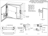
Figure 1. EH5700 Exploded Assembly Diagram
8 C1431SM-B (7/09)
Exploded Assembly Drawings
SCREWS
SUPPLIED
WITH VENT
COVER
PLATE
INTERNALLY MOUNTED TO REAR OF HOUSING
ON BASIC UNIT. BASIC UNITS COME WITH VENT
COVER PLATES INSTALLED. -1, -2, AND -3 UNITS
COME WITH #30 AND #23 INSTALLED.
TO UPPER WINDOW
BRACKET NUTS
TO STUD INSERTS
IN LID
30
23
3
B
A
M
A
4
C
5
L
6
7
8
9
10
11
12
13
A
E
16
A
B
14
A
E
15
24
F
19
22
H
G
J
D
F
K
20
21
17
B
A
25
26
28
29
A
B
2
B
1
27
18

Table A. EH5700 Series Exploded Assembly Parts List
Item Qty Description Part Number
1
2
3
4
5
6
7
8
9
10
11
12
13
14
15
16
17
18
19
20
21
22
23
24
25
26
27
28
29
30
2
2
2
2
1
1
1
2
1
1
1
2
1 ft
1
1
1
2
2
1
1
1
1
2
1
1
2
4
1
1
2
4
6 ft
8 ft
2
1
Gland Nut
Vent Cover Plate
Vent Cover Gasket
Label
Hole Plug, 3/8-inch Hard Nylon, Black
Pivot Pin
Body Hinge
Clip
Lid Hinge
Window Gasket
Window Glass, 4.50” x 5.50” x .250”
Ball End for Gas Spring
Window Gasket
Upper Window Bracket
Gas Spring
Lower Window Bracket
Power Supply Barrier
Grounding Clip
Camera Sled
Circuit Board
Circuit Board Insulator
Power Supply Barrier Cover
Foam Filter
Enclosure Lid (EH5729 Series)
Enclosure Lid (EH5723)
Latch (EH5723 Series)
Latch (EH5729 Series)
Enclosure Body (EH5729 Series)
Enclosure Body (EH5723 Series)
Latch Bracket (EH5723 Series)
Latch Bracket (EH5729)
Gasket (EH5723 Series)
Gasket (EH5729 Series)
Gland
Vent Grill
HF00-1352-3500
57004000COMP
570010001
LBLG10010
ZH3091
570010000
57004004COMP
125010001
57004106COMP
570010002
EH550010002
EH47004046COMP
EH110042
57004008COMP
EH470010005
57004009COMP
EH47004040COMP
570010004
EH55004100COMP
PCB9000276ASSY
EH450010256
MF00-4700-019A
EH550010045
57294001COMP
57234001COMP
LK01-0104-0400
LK01-0104-0400
57291001WA
57231001WA
57004007COMP
57004007COMP
GS01-0002-0430
GS01-0002-0430
HF00-1300-3500
57004005COMP
A
B
C
D
E
F
G
H
J
K
L
M
16
20
9
13
2
4
7
6
2
2
4
4
2
2
Internal Star Washer, #6 (EH5723 Series)
Internal Star Washer, #6 (EH5729 Series)
Screw, 6-32 x 3/8”, Pan Head, Phi
llips (EH5723 Series)
Screw, 6-32 x 3/8”, Pan Head, Phillips (EH5729 Series)
Screw, 6-32 x 5/8”, Flat Head, Phillips
Hex Nut, 10-32
Hex Nut, 6-32
Screw, 10-32 x 3/8”, Pan Head, Phillips
Screw, 4-40 x 1/4”, Pan Head, Phillips
Internal Star Washer, #4
Internal Star Washer, #10
Nylon Washer
Screw, 6-32 x 3/4”, Pan Head, Phi
llips
Screw, 6-32 x 1/4”, Pan Head, Phi
llips
ZH6LWSIS
ZH6LWSIS
ZH6-32X.375SPPG
ZH6-32X.375SPPG
ZH6-32X.625SFS
ZH10-32NUTSH
ZH6-32NUTSH
ZH10-32X.375SPP
ZH4-40X.250SPP
ZH4LWSIS
ZH10LWSIS
ZH200X437X62N
ZH6-32X.750SPP
ZH6-32X.250SPP
C1431SM-B (7/09) 9

Figure 2. EH5700L Exploded Assembly Diagram
23
K
E
26
22
F
A
20
C
21
A
18
16
19
17
15
14
TO STUD INSERTS
IN LID
A
F
TO UPPER WINDOW
BRACKET NUTS
13
12
11
L
D
A
N
10
A
C
9
32
31
8
7
M
5
TO PCB
3
B
C
4
A
C
6
27
1
25
A
C
30
29
33
28
J
H
24
G
34
10 C1431SM-B (7/09)

Table B. EH5700L Series Exploded Assembly Parts List
Item Qty Description Part Number
1
2
3
4
5
6
7
8
9
10
11
12
13
14
15
16
17
18
19
20
21
22
23
24
25
26
27
28
29
30
31
32
33
34
1
1
6 ft
8 ft
1
2
1
1
1
1
2
2
1
1
1
2
1
1 ft
1
2
1
1
1
1
4
4
1
2
4
1
1
2
4
2
1
1
1
2
2
1
Body for 29-inch (73.66 cm) Enclosure
Body for 23-inch (58.42 cm) Enclosure
Gasket (not shown) (EH5723L Series)
Gasket (not shown) (EH5729L Series)
Cover, 26-pin “D” Connector
Vent Cover Plate
RediLINK Wire Assembly
Gasket, Tilt Table Housing
Tilt Table
Enclosure Cradle
Vent Cover Gasket
Label
Hole Plug, 3/8-inch Hard Nylon, Black
Pivot Pin
Body Hinge
Stainless Steel Clip
Lid Hinge
Window Gasket
Window Gasket
Ball End for Gas Spring
Window Glass
Upper Window Bracket
Lower Window Bracket
Gas Spring
Screw, 10-32 x 3/8”, Pan Head, Phillips
Nylon Washer (not shown)
Camera Sled
Latch (EH5723L Series)
Latch (EH5723L Series)
Enclosure Lid (EH5729L Series)
Enclosure Lid (EH5723L Series)
Latch Bracket (EH5723L Series)
Latch Bracket (EH5729L Series)
Grounding Clip
Circuit Board
Circuit Board Insulator
Vent Grill
Foam Filter, (-1, -2, -3 only)
Power Supply Barrier
Power Supply Barrier Cover
57291000WA
57231000WA
GS01-0002-0430
GS01-0002-0430
90010026
57004000COMP
WIRA220050
GS05-0102-001A
9004016COMP
9554400COMP
570010001
LBLG10010
ZH3091
570010000
57004004COMP
125010001
57004006COMP
EH110042
570010002
EH47004046COMP
EH550010002
57004008COMP
57004009COMP
EH470010005
ZH10-32X.375GRY
ZH200X437X62N
EH55004100COMP
LK01-0104-0400
LK01-0104-0400
57294001COMP
57234001COMP
57004007COMP
57004007COMP
570010004
PCB9000276ASSY
EH450010256
57004005COMP
EH550010045
EH47004040COMP
MF00-4700-019A
A
B
C
D
E
F
G
H
J
K
L
M
N
16
20
2
9
13
2
4
7
2
2
2
4
2
2
2
Internal Star Washer, #6 (EH5723L Series)
Internal Star Washer, #6 (EH5729L Series)
Cap Screw, 10-32 x 1”, Allen Socket Head
Screw, 6-32 x 3/8”, Pan Head, Phil
lips (EH5723L Series)
Screw, 6-32 x 3/8”, Pan Head, Phillips (EH5729L Series)
Screw, 6-32 x 5/8”, Fl
at Head, Phillips
Hex Nut, 10-32
Hex Nut, 6-32
Screw, 10-32 x 3/8”, Pan Head, Phillips
Screw, 4-40 x 3/8”, Pan Head, Phillips
Internal Star Washer, #4
Internal Star Washer, #10
Screw, 6-32 x 3/4”, Pan Head, Phillips
Screw, 1/4-20 x 1/2”, Pan Head, Phillips
Screw, 6-32 x 1/4”, Pan Head, Phillips
ZH6LWSIS
ZH6LWSIS
ZH10-32X1.00CS
ZH6-32X.375SPP
ZH6-32X.375SPP
ZH6-32X.625SFS
ZH10-32NUTSH
ZH6-32NUTSH
ZH10-32X.375SPP
ZH4-40X.375SPP
ZH4LWS1S
ZH10LWSIS
ZH6-32X.750SPP
ZH1/420X.500SFS
ZH6-32X.250SPP
C1431SM-B (7/09) 11

Figure 3. Exploded Assembly Diagram for Blower and Circuit Board
K
3
C
J
TO
FAN
RED
22 GA. (1 FT.)
BLACK
22 GA. (1 FT.)
TO PC BOARD
SCREWS SUPPLIED
WITH BLANKING PLATE
2
1
4
5
6
7
G
F
12
8
H
A
B
B
E
9
B
11
C
C
B
A
10
12 C1431SM-B (7/09)

Table C. Exploded Assembly Parts List for Blower and Cicuit Board
Item Qty Description Part Number
1
2
3
4
5
6
7
8
9
10
11
12
1
2
1
1
1
2
1
1
1
1
1
1
1
1
1
2
Vent Grill
Foam Filter
24VDC Fan Recti
fier (for -2 ver. encl.)
Circuit Board Insulator
Circuit Board
Power Supply Barrier
Power Supply Barrier Cover
Fan Wire Cord with Plug (-1, -3
models only)
Fan Tube, 230 VAC
Fan, 24 VDC
Fan Tube, 120 VAC
Fan Plate (EH5723L/EH5729L Series)
Fan Plate (EH5723/EH5729 Series)
Standoff, 3.375” Length
Connector Plug
Connector Sockets
57004005COMP
EH550010045
PCB9000277ASSY
EH450010256
PCB9000276ASSY
EH47004040COMP
MF00-4700-019A
WIR432000
ED210015
955105W3
EH18013
57004010COMP
MF01-5701-010D
570010007
CN16-1820-0002
CN16-5821-0101
A
B
C
E
F
G
H
J
K
3
8
2
4
3
2
2
2
1
1
Cap Screw, 6-32 x 3/8”, Allen Socket Head
Internal Tooth Lock Washer, #6
Flat Washer, #6
Cap Screw, 6-32 x 3/8”, Allen Socket Head (for -1/-3 ver. encl.)
Cap Screw, 6-32 x 3/8”, Allen Socket Head (for -2 ver. encl.)
Screw, 4-40 x 3/8”, Pan Head, Phillips
Internal Tooth Lock Washer, #4
Circuit Board Grounding Clip
Cap Screw, 6-32 x 1/2”, Allen Socket Head (for -2 ver. encl.)
Nylon Spacer (for -2 ver. encl.)
ZH6-32X.375CS
ZH6LWSIS
ZH148X375X32
ZH6-32X.375CS
ZH6-32X.375CS
ZH4-40X.375SPP
ZH4LWSIS
570010004
ZH6-32X.500CS
ZH131X361X62N
C1431SM-B (7/09) 13

Figure 4. Exploded Assembly Diagram for Heaters and Circuit Board
2
1
A
C
E
F
B
TO PCB
3
D
G
B
4
5
6
7
14 C1431SM-B (7/09)

Table D. Exploded Assembly Parts List for Heaters and Circuit Board
Item Qty Description Part Number
1
2
3
4
5
6
7
1
2
2
2
1
4
1
2
1
1
Bracket/Heater Sink
Heater, 230 VAC
Heater, 24 VAC
Heater, 120 VAC
Connector Plug
Connector Sockets
Power Supply Barrier Cover
Power Supply Barrier
Circuit Board
Circuit Board Insulator
57004020COMP
HTR40220
HTR20024
HTR50120
CN16-1820-0004
CN16-5821-0101
MF00-4700-019A
EH47004040COMP
PCB9000276ASSY
EH450010256
A
B
C
D
E
F
G
2
6
2
4
2
2
2
2
Spacer, .500” Length
Internal Tooth Lock Washer, #4
Internal Tooth Lock Washer, #4
Screw 4-40 x 1/4”, Pan Head, Phillips
Grounding Clip
Screw, 6-32 x 1/4”, Pan Head, Phillips
Internal Star Washer, #6
Screw, 6-3 x 3/8”, Pan Head, Phillips
SPA8423
ZH4LWSIS
ZH4LWSIS
ZH4-40X.250SPP
570010004
ZH6-32X.250SPP
ZH6LWSIS
ZH4-40X.375SPP
C1431SM-B (7/09) 15

Figure 5. Exploded Assembly Diagram for Defroster
Table E. Exploded Assembly Parts List for Defroster
Item Qty Description Part Number
1
1
1
1
1
1
2
Window Defroster, 120 VAC
Window Defroster, 24 VAC
Window Defroster, 230 VAC
Connector Plug
Connector Sockets
HT07-0610-0605
HT07-0620-0605
HT07-0630-0605
CN16-1820-0002
CN16-5821-0101
1
2
TO
CIRCUIT BOARD
16 C1431SM-B (7/09)

Figure 6. Exploded Assembly Diagram for Window Wiper
6
10
4
13
J
N
SUPPLIED WITH
BLOWER KIT
15
2
14
7
TO PCB9000275ASSY
5
D
F
14
I
H
3
12
F
E
11
9
1
N
A
L
J
N
M
N
J
N
8
K
I
J
N
B
TO PCB9000275ASSY
C1431SM-B (7/09) 17

Table F. Exploded Assembly Parts List for Window Wiper
Item Qty Description Part Number
1
2
3
4
5
6
7
8
9
10
11
12
13
14
15
16
17
1
1
1
1
1
1
1
1
1
1
1
2
1
1
1
2
3
1
1
Cam Assembly
Wiper Arm Assembly
Wiper Shaft (EH5729 Series)
Wiper Shaft (EH5723 Series)
Wiper Driver Circuit Board Mount
Wiper Motor
Wiper Driver Circuit Board Cover
Flex Coupling
Fan Plate
Bronze Bearing Flange
Wiper Driver Circuit Board
5/32 Hex 3/16 x 2-56 Standoff
Switch Actuator
Switch
Transformer (-1, -3 models)
Teflon Bearing Flange
Wiper Blade (by the inch)
Support Bracket
Switch Shield (not shown)
WW57001000ASSY
WW57001003ASSY
MF00-5701-015A
MF00-5701-029A
WW57004013COMP
MR02-0002-2100
WW57004014COMP
570010014
MF01-5701-010D
776003
PCB9000275ASSY
SPA8300
SWIJS221
SWI1SM1
TRF21240.70.7CM
WW550010001
WW570010050
MF01-5701-028A
MF01-5701-0333A
A
B
D
E
F
H
I
J
K
L
M
N
Not Shown
1
12
2
2
4
Variable
Variable
9
2
1
Variable
Variable
Variable
Grommet
Nylon Washer #6
Hex Nut, 2-56
Screw, 2-56 x 3/4-inch, Pan Head, Phillips
Internal Tooth Lock Washer, #2
Screw, 4-40 x 1/4-inch, Pan Head, Phillips
Internal Tooth Lock Washer, #4
Cap Screw, 6-32 x 3/8-inch, Allen Socket Head
Cap Screw, 4-40 x 3/8-inch, Allen Socket Head (WW5723-1 only)
Nut, 6-32, Acorn
Hex Nut, 6-32 (-1, -3)
Internal Tooth Lock Washer, #6
Hex Nut, 4-40
GR02170
ZH131X361X62N
ZH2-56NUTSH
ZH2-56X.750SPS
ZH2LWSIS
ZH4-40X.250SPP
ZH4LWSIS
ZH6-32X.375CS
ZH4-40X.375CS
ZH6-32NUTCA
ZH6-32NUTSH
ZH6LWSIS
ZH4-40NUTSHG
18 C1431SM-B (7/09)

Figure 7. EH5700/EH5700L Series Input Wiring Diagram
KIT # BK57-2
KIT # BK57-1 (120 V)
KIT # BK57-3 (230 V)
FAN
24 VDC
FAN
120/230 V
PCB9000277ASSY
RED
BLK
RED
BLK
1 2
PLUG
1 2
PLUG
BLK
BLK
PLUG
1
2
3
4
WHT
WHT
RED
HEATER
24/120/230 V
HEATER
24/120/230 V
RED
KIT # HK57-1
KIT # HK57-2
KIT # HK57-3
DEFROSTER
24/120/230 V
KIT # WD57-1
KIT # WD57-2
KIT # WD57-3
WHT
WHT
PLUG
1
2
KIT # WW57-1, -3
TO SWITCH FROM -1, TO -3,
USE JUMPER ON PC BOARD
PCB9000275
120/230 VAC
M
BLK
WHT
BLU
1 2 3 4
PLUG
BLU
WHT
BLK
BLK
BLK/WHT
BLU
BLU/WHT
BRN
BRN/WHT
TRF21240.70.7CM
BLU
WHT
BLK
BLK
WHT
BLU
KIT # WW57-2
PCB9000275
24 VAC
M
1 2 3 4
PLUG
CAUTION
HIGH
VOLTAGE
WIPEON
WASH ON
W/W
W/W
DEF
CAM 1
HTR FAN
FAN
1
1
1
1
P7
P5
P2
TB2
TH1
TH2
TB4
P6
TB3
HTRS
SPARES
AC
HI NT GND 1 2
1
1 2 3 4 5 6 7 8 9 10
PCB9000276 (O/I-PCB)
LENS CONTROL
LENS
J1
5
INPUTS
1
LENS
COM
FOCUS
ZOOM
IRIS
PRST
COM
PRST
FOCUS
PRST
ZOOM
PRST
HI
CAM
CAM
TB1
1
P1
P3
1
1 2
CAM 2
WHT/ORG
WHT/BRN
WHT/RED
WHT/BLU
BLK/WHT
YEL/WHT
RED/WHT
GRN/WHT
LENS CONN W/PRESETS
(SUPPLIED WITH PCB)
PELCO
LENS
CONN
PLUG
1 2
PLUG
1 2 3
PLUG
1 2 3
OUTLET
PLUG
120 V
OPTIONAL
CAMERA
POWER
(SUPPLIED
WITH PCB)
*
CAMERA POWER
24/120/230 VAC
(SUPPLIED
WITH PCB)
*
KIT # O/I-OUTLET
LENS CONN OPTIONS
CPC CONN.
KIT # O/I-IPP
4 3 2 1 8 9 7 6 5
NOT USED
BRN
BLU
BRN
BLU
GRN
BLK
WHT
GRN
* CONNECT CAM 1 TO CAMERA WHEN THE CAMERA’S
POWER IS THE SAME AS THE AC POWER INPUT.
CONNECT CAM 2 TO CAMERA WHEN THE CAMERA’S
POWER IS DIFFERENT FROM THE AC POWER INPUT.
C1431SM-B (7/09) 19
Wiring Diagrams and Circuit Boards

Figure 8. Wiring Diagram for Optional Circuit Board (O/I-PCB)
ENCLOSURE CIRCUIT BOARD
REFER TO FIGURE 9 FOR COMPONENT LOCATIONS
EH5700L SERIES ONLY
20 C1431SM-B (7/09)
/