Page is loading ...

Circle the model of your cooler and record the
serial number below.
Read Carefully All Of This Manual Before
Installing The Unit.
Read And Save These Instructions
Serial #
Encierre con un circulo el modelo de su enfriador y
escribe el número de serie abajo.
Lea Con Cuidado Todo Este Manual Antes De Instalar
La Unidad.Número De Serie
Table Of Contents
Safety Instructions .............................................................................2
Operation ............................................................................................2
Installation Instructions ...................................................................2-3
Maintenance Section ..........................................................................3
Troubleshooting .................................................................................4
Warranty .............................................................................................4
Electrical Wiring Diagrams ................................................................5
General Specifi cations .......................................................................6
Parts List - Wet Section (All models) .............................................6-7
Parts List - Blower Section (AD100B, AD150B, AD200B) ..............8
Parts List - Blower Section (AS100B, AS150B, AS200B) ................9
Parts List - Blower Section (AU200B) ............................................10
Parts List - Blower Section (Single Inlet Coolers) ...........................11
Motor Specifi cations ........................................................................12
Pulley and Belt Kit Specifi cations ...................................................12
Spanish (Instrucciones en Español) ............................................ 13-16
Models
(Double Inlet)
AD100, AS100, AD10012, AS10012
AD150, AS150, AD15012, AS15012
AD20012, AS20012, AU20012
(Single Inlet)
SAD100, SAS100, SAD10012, SAS10012
SAD150, SAS150, SAD15012, SAS15012
110526 7-14
Vea el Español en el interior.
The New Industrial

1105262
Safety Rules
1. Read instructions carefully.
2. Disconnect all electrical service that will be used for the unit before
you begin the installation.
3. Electrical hook up should be done by a qualifi ed electrician, so that all
electrical wiring will conform to your local standards.
4. For maximum safety, make sure cooler cabinet is properly grounded
to a suitable ground connection.
5. Cooler must be connected to proper line current, voltage and cycle, as
stamped on cooler motor and pump motor specifi cation plate.
6. Do not allow pump to tip over and become submerged.
7. Always TURN OFF POWER before performing any maintenance.
WARNING: To reduce the risk of fi re, electric shock and injury
to persons, this cooler must be installed with motors and pumps listed
on the notice decal and marked to indicate suitability with this model.
Other motors and pumps cannot be substituted.
Operation
For the best cooling performance, if the pads are dry, pre-wet the pads by
running the pump for a few minutes before starting the blower.
These coolers may also be used without water for ventilation purposes.
When outside air is cool (for example, at night) or when humidity is high
the water pump can be turned off.
Important: To cool effi ciently, you must exhaust the stale or used air
from the building. Open windows or doors or use exhaust fans located
away from the cooler and in the direction you wish to cool the air. The air
will fl ow in the direction of the exhaust openings. A common guide for
the amount of exhaust opening needed is to have at least 2 square feet of
opening per 1000 CFM.
Installation
CAUTION: Make sure that the mounting surface is strong
enough to support the operating weight of the cooler when in use.
(For operating weight, see the general specifi cation table.)
CAUTION: Do not start cooler until installation is complete
and unit has been tested for rigidity.
CAUTION: Make sure all bolts are securely tightened before
starting the cooler.
• Wet sections. Attach the lift brackets to the top of the
blower module and wet module using the included
1/4-20 bolts. See Fig. 1. Attach the connector brack-
ets in like manner near the bottom of the unit. Bring
the two sections together and secure them using the
provided 3/8-16 nut, bolt and washers.
• Ductwork. See the General Specifi cation table for dimensions of duct
opening. For down discharge units, the duct must go inside the opening.
Size these ducts slightly smaller than the duct opening in the cooler.
The side and up discharge units have a 1 inch fl ange. Size these ducts
larger than the duct opening to fi t over the fl ange of these units.
Note: Curbs are not provided. The installer is responsible for pro-
viding curbs or other means to support the cooler. We recommend
that roof penetration only be as large as ductwork coming from unit.
Water drain should be outside curb if possible.
Motor Installation
• Motor mounting. Slide the heads
of the provided carriage bolts into
the slots of the adjustable channels.
Slide these channels sideways in
the slotted holes to align with the
holes in the motor base and to align
the motor shaft with the blower
Water Connections
• Overfl ow assembly. Remove nut and place
nipple through the hole in the pan, with
the rubber washer between the pan and the
head of the drain nipple (Fig. 5). Screw
on nut and draw up tight against bottom of
pan. Insert overfl ow pipe in nipple to retain
water. Overfl ow pipe may be removed to
drain pan when necessary. The male threads
of the Nipple are standard 3/4” garden hose
threads. To drain water away from unit, drain pipe can be attached to
the nipple using a NPT to GHT adapter which can be purchased at a local
hardware store. Follow local plumbing codes.
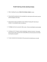
• Pump. The pump must be secured to prevent it form tipping over. Se-
cure the pump to the pump mounting bracket (item 16 in parts drawing).
Remove a nut located under the head of the pump, place the pump bolt
though the hole in the mounting bracket, and secure with the nut that was
previously removed. Plug pump into receptacles. Retain pump cords
to internal braces to prevent cords from dropping into water reservoirs
or contacting moving components.
• Supply water. Run a water supply line to the unit. Each wet section
requires a 3/8 inch tube connection to the fl oat valve. The double inlet
units will have two fl oat valves, one for each wet section. Note: Do
not use water supplied from a water softener.
• Float valve. Refer to Fig. 6 to install fl oat. Remove items 1, 2, 3, and 4.
Insert fl oat body (5) through hole in splash plate (9) and back post panel
closest to access panel as shown. Install washer (1) and nut (2). Tighten
pulley. Mount the motor to the motor mount using these carriage bolts
and the washers and nuts provided (see Fig. 2). Make sure all bolts are
securely tightened.
• Motor pulley. Install the motor pulley
so that it aligns with the blower pulley
(see Fig. 3) and tighten set screw. See
page 3 for instructions on adjusting pul-
ley.
Electrical Connection
NOTE: Local building code regulations must be observed.
WARNING: Disconnect all electrical services that are used for
this unit before beginning any service to the cooler.
• Electrical supply. Cooler must be supplied with the proper line cur-
rent, voltage and frequency, as stamped on blower motor and pump
motor specifi cation plate. See the wiring diagrams on page 4 for typical
electrical connections. Note: Connecting improper voltage to motor
will void motor warranty.
• Wire sizing. The conductor sizes are to be determined by motor loads
and length of run per national and local electrical codes.
• Switches or contactors. Motors require switches or contactors of
proper current capacity and should be sized and installed by a qualifi ed
electrician.
• Wiring. The electrical junction box
is located in the upper inside of the di-
vider channel. Remove the two screws
and pull the box out from the channel
to access wiring (Fig. 4). Connect the
pump supply wiring to the pump recep-
tacles (See the pump wiring diagrams
on the next page). Connect the motor
supply wiring directly to the blower
motor.
WARNING: Make sure that cooler cabinet is properly grounded
to a suitable ground connection for maximum safety.
Fig. 2
Blower
Housing
Motor
Pulley
Blower
Pulley
Fig. 3
Screws
Junction Box
Fig. 4
Rubber Washer
Overfl ow Pipe
Nipple
Bottom Pan
Nut
Fig. 5
Fig. 1

110526 3
to keep fl oat from turning. Place nut
(4) and ferrule (3) on water supply line.
Connect to fl oat fi tting and tighten until
water tight. Turn on water supply and
check for leaks. Loosen screw (6) and
adjust rod (7) until water level is within
1” of top of reservoir. Tighten screw (6).
Slide fl oat shield (8) over fl oat body (5)
until it snaps into place.
• Bleed-Off. Use of the bleed-off kit is recommended to prevent scale build
up by bleeding off small amounts of circulating water during operation.
Amount to bleed-off will vary depending on water quality. Start with
1gph per 1000cfm of airfl ow. If scale builds up on media, increase the
amount of bleed-off. Do not add any type of water treatment chemicals
to the water since they may damage the evaporative media.
Pulley And Belt Adjustments
• Pulley adjustment. With an ammeter, check the motor amperage.
Adjust the pulley until the amperage draw on the motor is just below
that specifi ed on the motor nameplate. To ad-
just the pulley, loosen the adjustment set screw
and rotate the sheave. Tighten the set screw
so that it is over a fl at area, otherwise thread
damage will occur. To increase amperage
draw, increase pulley diameter. To decrease
amperage draw, decrease pulley diameter (see
Fig. 7). Recheck belt alignment.
CAUTION: Always check the amperage
of the motor after adjusting pulley to be certain it does not exceed
the amperage stamped on the motor specifi cation plate. Improper
pulley adjustment will overload and burn out the motor.
• Belt tension. Loosen the motor mount
bolts and slide the motor back until the
belt is properly tensioned. A 3 lb. force
should defl ect the belt 3/4 inches (see Fig.
8). Retighten motor mount bolts. Do not
adjust pulley to tighten belt.
Maintenance
WARNING: Before doing any maintenance be sure to disconnect
from power source. This is for your safety.
Spring Start-Up
• Belt tension. Check belt tension and readjust if needed.
• Grease bearings. The blower bearings in this unit should be greased
once a year with a good grade of ball bearing grease.
• Cleaning pads. A clean pad is more absorbent, effi cient and will give
more cool air. Annually, or when required, using a garden hose with
nozzle, back wash to clean out the openings, then clean off the inlet
face any scale or other obstruction to the passages. Slight scraping
may be required to remove hardened scale.
• Pad replacement. The pads should be replaced after 5 years or if
necessary. To change pads, remove top access panel, remove grill,
and disconnect water delivery tube. Remove water distributor holder
and lift out media sections. Replace with the same type media. You
can purchase them from your dealer.
IMPORTANT: In order to get the best performance from your
cooling pads, they must be installed properly. If you have purchased
a pad with two equal angles, the following instructions can be dis-
regarded. Pads must always be installed with the steeper fl ute angle
sloping down towards the air entering side (Fig. 9). The reason is
simple. The steeper angle
puts more water on the
hot, dry, dirty side of the
pad where it is needed
most. It also counteracts
the tendency of the air to
push the water toward the
back of the pad.
• Cleaning pump. Cleaning the pump is necessary once a year at
start-up. For your safety, disconnect from power source and unplug
pump. Remove the pump from the mount bracket. Remove the
base of the pump (Fig. 10). Clean the pump and turn the impeller to
ensure free operation. Remove the pump spout and check for any
blockage. After cleaning, reinstall the base onto the pump. Reattach
the pump to the mount in the
cooler to ensure that the pump
will not overturn. Do not forget
to replace the spout and water
delivery tube onto the pump
outlet. The pump has automatic
reset thermal protection. Pump
will operate normal again after
obstruction is cleared.
• Bleed off. Check bleed-off valve to be sure it is not clogged.
Winter Shut Down
• Drain water. Always drain all of the water out of the cooler and water
supply line when not in use for prolonged periods, and particularly at
the end of the season. Keep the water line disconnected from both
the unit and water supply so that it does not freeze.
• Disconnect from power supply when not in use for extended
periods of time.
• Cover unit. To protect the life of the fi nish, a cover for the unit is
suggested in extended periods of non use.
Additional maintenance may be needed throughout the season to keep
media and unit functioning effi ciently. By following the operating,
installation, and maintenance suggestions as outlined, you can get
many years of effi cient and satisfactory service from your cooler. In
the event additional information is desired, your dealer will be more
than glad to assist you in every possible way.
Ground
Blue/Black
White
Brown
= Wire Nut
Orange
Green
Green
Orange
Brown
White
Blue/Black
Pump
Com.
To
Switch
Com.
Pump
Blue/Black
White
Brown
Orange
Green
Green
Orange
= Wire Nut
Brown
White
Blue/Black
Ground
To
Switch
120 Volts 240 Volts
Pump Wiring Diagrams
Decrease
Amperage
Fig. 7
45°
15°
Entering
Air
Leaving Air
Fig. 9
Impeller
Remove
Base
Fig. 10
Fig. 8
3 Lb.
3/4 Inches
1
2
3
4
5
7
8
Fig. 6
6
9

1105264
Limited Warranty
This warranty is extended to the original purchaser of an evaporative cooler installed and used under normal conditions. It does not cover damages in-
curred through accident, neglect, or abuse by the owner. We do not authorize any person or representative to assume for us any other or different liability
in connection with this product.
Terms And Conditions Of The Warranty
Lifetime Limited Coverage on water reservoir against any leakage due to defects in material. From date of purchase, if any original component part fails
due to defect in material or factory workmanship only, we will provide the replacement part as follows:
One year on the cabinet components.
Two years on the evaporative media.
Exclusions From The Warranty
We are not responsible for any incidental or consequential damage resulting from any malfunction.
We are not responsible for any damage received from the use of water softeners, chemicals, de-scale material, plastic wrap, or if a motor of a higher
horsepower than what is shown on the serial plate is used in the unit.
We are not responsible for the cost of service calls to diagnose cause of trouble, or labor charge to repair and/or replace parts.
How To Obtain Service Under This Warranty
Contact the Dealer where you purchased the evaporative cooler. If for any reason you are not satisfi ed with the response from the dealer, contact the
Customer Service Department: 5800 Murray Street, Little Rock, Arkansas 72209. 1-800-643-8341. E-mail: info@championcooler.com, Web: www.
championcooler.com.
This limited warranty applies to original purchaser only.
Failure to
start or no air
delivery
Inadequate
air delivery
with cooler
running
Musty or
unpleasant
odor
1. No electrical power
to unit
• Fuse blown
• Circuit breaker tripped
2. Belt too loose or tight
3. Motor overheated
• Belt too tight
• Blower bearings dry
• Motor bearings dry
• Motor pulley diameter
too large
4. Motor locked
1. Insuffi cient air exhaust
2. Belt too loose
3. Pads plugged
4. Insuffi cient water fl ow
over pads
1. Stale or stagnate water
in cooler
2. Pads not wetting
properly
• Dist. tube holes
clogged
• Pump not working
properly
• Insuffi cient water fl ow
over pads
1. Check power
• Replace fuse
• Reset breaker
2. Adjust belt tension
3. Determine cause of
overheating
• Adjust belt tension
• Grease blower bear-
ings
• Oil motor bearings
• Adjust pulley to cor-
rect diameter
4. Replace motor
1. Open windows or
doors to increase air
fl ow
2. Adjust belt tension or
replace if needed
3. Clean pads
4. Clean distribution
system
1. Drain pan and clean
pads
2. Check water distribu-
tion system
• Clean
• Replace or clean
pump (Unplug)
• Clean water distribu-
tion system
1. Check voltage
2. Adjust belt tension
3. Grease or replace
bearings (Disconnect
unit)
4. Grease bearings
5. Adjust pulley so full
load ampere rating of
motor is not exceeded
6. Replace motor
1. Grease bearings
2. Inspect and realign
(Disconnect unit)
3. Tighten loose parts
1. Open windows or
doors to increase air
fl ow
2. Check water distribu-
tion system
• Clean pads
• Clean
• Replace or clean
pump (Unplug)
1. Open doors or win-
dows
Motor
cycles on
and off
Noisy
Inadequate
cooling
Excessive
humidity in
house
1. Low voltage
2. Excessive belt tension
3. Blower shaft tight or
locked
4. Bearings dry
5. Motor pulley diameter
too large causing motor
overload
6. Faulty motor
1. Bearings dry
2. Wheel rubbing blower
housing
3. Loose parts
1. Inadequate exhaust in
house
2. Pads not wet
• Pads plugged
• Dist. tube holes
clogged
• Pump not working
properly
1. Inadequate exhaust
Problem Possible Cause Remedy Problem Possible Cause Remedy
Troubleshooting Guide
Register your product online at www.championcooler.com/index.php/cooler-warranty-registration

110526 5
Typical Electrical Wiring Diagrams
WARNING: Electrical hookup should be performed by a qualifi ed electrician. All electrical wiring must conform to national and local
standards.
NOTE 1. All switches, motor starters, transformers, fuses, junction boxes, receptacles, receptacle boxes, cover plates, and conductors shall be supplied by the
installer.
NOTE 2. The national electric code requires a disconnect switch located at equipment if the main disconnect at equipment controller is not visible from the equip-
ment. If more than one disconnect is used they must be mounted adjacent to one another.
NOTE 3. A receptacle for a NEMA 5-15P plug is required for 120V recirculating pump and a receptacle for a NEMA 6-15P plug for 230V pump.
NOTE 4. The control contacts may be part of a switch, thermostat or other control device.
• Three phase single speed blower motor
• Three pole motor starter with overload
protection
• 120V single phase control and pump shown.
If 240V control and pump are to be used, then
both legs of power supply must be fused.
Main Disconnects
See Note 1
Control Contacts
See Note 4
Disconnect Switch At Cooler
See Note 1&2
Cooler Cabinet
See Note 3
Pump Motor
Equipment
Ground
Blower Motor
Motor Starter With
Overload Protection
Sized To Match Motor
Full Load Current
See Note 1
L2
L1
H
P
T1
T2
T3
Disconnect Switch
At Cooler
See Notes 1 & 2
Gnd
208, 240, or 480V
3 Phase
Power Supply
120V
1 Phase
Power Supply
Fuses
See Note 1
Gnd
L3
L1
N
Gnd
208, 240, or 480 Volt, 3 Phase Blower & 120 Volt 1 Phase Pump & Control Electric Supply
N
Gnd
Motor Starter With
Overload Protection
Sized To Match Motor
Full Load Current
See Note 1
Fuses
See Note 1
Main Disconnect
See Note 1
Disconnect Switch At Cooler
See Notes 1 & 2
Disconnect Switch At Cooler
See Notes 1 & 2
Pump Motor
Blower Motor
Equipment
Ground
T1
T2
T3
Cooler Cabinet
See Note 3
L2
Transformer
See Note 1
208, 240 or 480V
3 Phase
Power Supply
H
P
• Three phase single speed blower motor.
• Three pole motor starter with overload protection.
• 120V single phase pump powered by a transformer.
Transformer may be omitted when 240V control &
pump are used with a 240V supply.
Typical Control Contacts
Function and Connection
L - Low Fan
P - Pump
H - Hi Fan
L1 - Supply Power
Function Connection
Off None
Pump Only L1-P
Hi-Cool L1-H
* Low-Cool L1-L & L1-P
Hi-Fan L1-H
* Low-Fan L1-L
* Omit for single speed blower motor
• 115 Volt single phase blower motor.
• 120 Volt pump motor.
• Diagram shown for two speed motor.
Low speed circuit drawn with dashed
lines is not required for single speed.
Equipment
Ground
Pump Motor
Blower Motor
Cooler Cabinet
Fuses
See Note 1
Main Disconnect
See Note 1
120 Volts
1 Phase
Power Supply
N
H
Disconnect Switch At Cooler
See Notes 1 & 2
L1
N
See Note 3
L
GndGnd
120 Volt, 1 Phase Electric Supply
Control Contacts
See Note 4
P
• 230 Volt single phase blower motor.
• 120V pump motor shown. Trans-
former may be omitted when a 240V
pump is used with a 240V supply
• Diagram shown for two speed motor.
Low speed circuit drawn with dashed
lines is not required for single speed.
Equipment
Ground
Pump Motor
Blower Motor
Cooler Cabinet
See Note 3
Transformer
Fuses
See Note 1
208 or 240V
1 Phase
Power Supply
L2
H
P
Control Contacts
See Note 1
Disconnect Switch At Cooler
See Notes 1 & 2
Gnd
L
240 Volt, 1 Phase Electric Supply
Main Disconnect
See Note 1
L1
L2
Gnd
120V
Gnd
Gnd
L3
L1
120
V
Control Contacts
See Note 4
208, 240, or 480 Volt, 3 Phase Blower Electric Supply With Transformer For Pump & Control

1105266
Model No.
Modelo
*Weight (lbs.)
Peso (libras)
Cabinet Dimensions (in.)
Dimensiones De La Caja (pulgadas)
Duct Opening (in.)
Abertura De Ducto (pulgadas)
*Dry
Seco
*Operating
Lleno
Height
Altura
Width
Anchura
Depth
Profundidad
Width
Anchura
Height
Altura
AD100 517 717 44 81 3/4 45 21 3/4 21 3/4
AS100 511 711 44 81 3/4 45 21 3/4 21 3/4
AD10012 571 812 44 89 3/4 45 21 3/4 21 3/4
AS10012 565 806 44 89 3/4 45 21 3/4 21 3/4
AD150 648
863 54 85 48 1/4 26 7/8 26 7/8
AS150 640 856 54 85 48 1/4 26 7/8 26 7/8
AD15012 714 974 54 93 48 1/4 26 7/8 26 7/8
AS15012 706 967 54 93 48 1/4 26 7/8 26 7/8
AD20012 928 1208 59 1/4 105 1/4 60 1/4 31 3/4 31 3/4
AS20012 914 1194 59 1/4 105 1/4 60 1/4 31 3/4 31 3/4
AU20012 914 1194 59 1/4 105 1/4 60 1/4 31 3/4 31 3/4
SAD100 417 517 44 63 3/8 45 21 3/4 21 3/4
SAS100 411 511 44 63 3/8 45 21 3/4 21 3/4
SAD10012 444 565 44 67 3/8 45 21 3/4 21 3/4
SAS10012 438 559 44 67 3/8 45 21 3/4 21 3/4
SAD150 533 641 54 66 5/8 48 1/4 26 7/8 26 7/8
SAS150 525 633 54 66 5/8 48 1/4 26 7/8 26 7/8
SAD15012 566 696 54 70 5/8 48 1/4 26 7/8 26 7/8
SAS15012 558 688 54 70 5/8 48 1/4 26 7/8 26 7/8
*Does not include motor weight. / No incluye el peso del motor.
General Specifi cations / Especifi caciones Generales
Replacement Parts / Piezas De Repuesto
SAS/SAD100W, SAS/SAD10012W, SAS/SAD150W, SAS/SAD15012W
AS/AD100W, AS/AD10012W, AS/AD150W, AS/AD15012W, AS/AD/AU20012W

1105268
No.
N° Description / Descripción AD100B AD150B AD200B
1. Top, Cabinet / Tapa De La Caja ------------------------------------------------------------- 218115-003 218116-008 216117-003
2. Bottom, Cabinet / Base De La Caja ---------------------------------------------------------- 318115-005 318116-010 318117-007
3. Corner Post, Left / Poste De Esquina, Izquierdo ------------------------------------------- 318115-013 318116-018 318117-018
3A. Corner Post, Right / Poste De Esquina, Derecho------------------------------------------- 318115-025 318116-050 318117-038
4. Divider Channel / Canal Divisora ------------------------------------------------------------ 218115-014 218116-019 218117-013
5. Cut-Off Plate / Placa Limitadora -------------------------------------------------------------320102-002 318112-004 318112-003
6. Blower Housing / Caja De La Rueda --------------------------------------------------------322115-002 320116-001 320117-001
7. Blower Wheel / Rueda ------------------------------------------------------------------------- 21BW 25BW 29BW-BR
8. Pulley, Blower Wheel / Polea De La Rueda ------------------------------------------------ 110297 110298 110298
9. Drive Belt / Correa ----------------------------------------------------------------------------- † (2) † (2) † (2)
10. Motor / Motor ----------------------------------------------------------------------------------- * * *
11. Pulley, Motor / Polea Del Motor ------------------------------------------------------------- † † †
12. Channel Retainer / Soporte De Canal -------------------------------------------------------- 214007-001 (2) 214007-006 (2) 214109-001 (2)
13. Motor Mount Support / Soporte Para La Montura Del Motor --------------------------- 214118-005 (3) 214116-008 (3) 206102-001 (3)
14. Motor Mount Adjustable Channel / Montura Ajustable Del Motor --------------------- 214112-002 (2) 214112-004 (2) 214112-004 (2)
15. Motor Mount Crossbrace / Travesaño De La Montura Del Motor ---------------------- 214001-005 214001-009 214001-007
16. Bearings, Blower Wheel Shaft / Cojinetes Del Eje De La Rueda ------------------------110355 (2) 110356 (2) 110356 (2)
17. Front Panel / Panel Del Frente---------------------------------------------------------------- 318115-024 318116-048 318117-011
18. Lift Bracket / Soporte De Levantamiento --------------------------------------------------- 212104-001 (8) 212104-001 (8) 212104-001 (8)
19. Inspection Panel / Panel De Inspección -----------------------------------------------------220115-003 (2) 220116-004 (2) 220116-007 (2)
20. Electrical Junction Box / Caja De Empalme ------------------------------------------------ 322009-003 322009-003 322009-003
21. Bearing Mount Support / Soporte Para Los Cojinetes ------------------------------------ 206100-002 (2) 206100-004 (2) 206100-005 (2)
22. Shaft, Blower Wheel / Eje De La Rueda ---------------------------------------------------- 110157 110158 110159
23. Receptacle, Pump / Toma De Corriente De La Bomba ------------------------------------ 110361 (2) 110361 (2) 110361 (2)
24. Connect Bracket / Abrazadera De Unión --------------------------------------------------- 214121-001 (8) 214121-001 (8) 214121-001 (8)
* See motor specifi cation table. Motor sold separately. / Vea la tabla de especifi caciones del motor. Motor se vende por separado.
† See pulley and belt table. Sold separately. / Vea la tabla de especifi caciones del polea y correa. Se venden por separado.
NOTE: Standard hardware items may be purchased from your local hardware store.
NOTA: Artículos de uso corriente pueden comprarse en la ferretería de su localidad.
Replacement Parts / Piezas De Repuesto
AD100B, AD150B, AD200B

11052610
No.
N° Description / Descripción AU200B
1. Top, Cabinet / Tapa De La Caja ...........................................................................................................................316117-007
2. Bottom, Cabinet / Base De La Caja .......................................................................................................................316117-004
3. Corner Post, Left / Poste De Esquina, Izquierdo ...................................................................................................318117-020
3A. Corner Post, Right / Poste De Esquina, Derecho ..................................................................................................318117-038
4. Divider Channel / Canal Divisora .........................................................................................................................218117-013
5. Cut-Off Plate / Placa Limitadora...........................................................................................................................318112-003
6. Blower Housing / Caja De La Rueda ....................................................................................................................320117-001
7. Blower Wheel / Rueda ...........................................................................................................................................29BW-BR
8. Pulley, Blower Wheel / Polea De La Rueda .......................................................................................................... 110298
9. Drive Belt / Correa ................................................................................................................................................† (2)
10. Motor / Motor ........................................................................................................................................................*
11. Pulley, Motor / Polea Del Motor ...........................................................................................................................†
12. Channel Retainer / Soporte De Canal .................................................................................................................... 214109-002 (2)
13. Motor Mount Support / Soporte Para La Montura Del Motor .............................................................................. 206102-003 (2)
14. Motor Mount Adjustable Channel / Montura Ajustable Del Motor......................................................................214112-004 (2)
15. Motor Mount Crossbrace / Travesaño De La Montura Del Motor ....................................................................... 214001-007
16. Bearings, Blower Wheel Shaft / Cojinetes Del Eje De La Rueda .........................................................................110356 (2)
17. Front Panel / Panel Del Frente ..............................................................................................................................318117-011
18. Lift Bracket / Soporte De Levantamiento ..............................................................................................................212104-001 (8)
19. Inspection Panel / Panel De Inspección .................................................................................................................220116-007 (2)
20. Electrical Junction Box / Caja De Empalme .........................................................................................................322009-003
21. Bearing Mount Support / Soporte Para Los Cojinetes ..........................................................................................206100-005 (2)
22. Shaft, Blower Wheel / Eje De La Rueda ...............................................................................................................110159
23. Receptacle, Pump / Toma De Corriente De La Bomba .........................................................................................110361 (2)
24. Blower Support Bracket / Soporte De La Caja De La Rueda ...............................................................................218122-005 (2)
25. Connect Bracket / Abrazadera De Unión ..............................................................................................................214121-001 (8)
* See motor specifi cation table. Motor sold separately. / Vea la tabla de especifi caciones del motor. Motor se vende por separado.
† See pulley and belt table. Sold separately. / Vea la tabla de especifi caciones del polea y correa. Se venden por separado.
NOTE: Standard hardware items may be purchased from your local hardware store.
NOTA: Artículos de uso corriente pueden comprarse en la ferretería de su localidad.
Replacement Parts / Piezas De Repuesto
AU200B

110526 11
No.
N° Description / Descripción SAD100B SAS100B SAD150B SAS150B
1. Top, Cabinet / Tapa De La Caja ............................................................. 218115-003 218115-003 218116-008 218116-008
2. Bottom, Cabinet / Base De La Caja ......................................................... 318115-005 318115-020 318116-010 318116-026
3. Corner Post, Left / Poste De Esquina, Izquierdo ..................................... 318115-013 318115-013 318116-018 318116-018
3A. Corner Post, Right / Poste De Esquina, Derecho .................................... 318115-025 318115-025 318116-050 318116-050
4. Divider Channel / Canal Divisora ........................................................... 218115-014 (2) 218115-014 (2) 218116-019 (2) 218116-019 (2)
5. Cut-Off Plate / Placa Limitadora.............................................................320102-002 320102-002 318112-004 318112-004
6. Blower Housing / Caja De La Rueda ...................................................... 322115-002 322115-002 320116-001 320116-001
7. Blower Wheel / Rueda .............................................................................21BW 21BW 25BW 25BW
8. Pulley, Blower Wheel / Polea De La Rueda ............................................ 110297-1 110297-1 110298-1 110298-1
9. Drive Belt / Correa .................................................................................. † † † †
10. Motor / Motor .......................................................................................... * * * *
11. Pulley, Motor / Polea Del Motor ............................................................. † † † †
12. Channel Retainer / Soporte De Canal ...................................................... 214007-001 (2) 214007-001 214007-006 (2) 214007-006
13. Motor Mount Support / Soporte Para La Montura Del Motor ................ 214118-005 (2) 214115-004 (2) 214116-008 (2) 214116-009 (2)
14. Motor Mount Adjustable Channel / Montura Ajustable Del Motor........ 214112-002 (2) 214112-002 (2) 214112-004 (2) 214112-004 (2)
15. Motor Mount Crossbrace / Travesaño De La Montura Del Motor ......... 214001-005 214001-005 214001-009 214001-009
16. Bearings, Blower Wheel Shaft / Cojinetes Del Eje De La Rueda ........... 110355 (2) 110355 (2) 110356 (2) 110356 (2)
17. Front Panel / Panel Del Frente ................................................................ 318115-024 318115-009 318116-048 318116-014
18. Lift Bracket / Soporte De Levantamiento ................................................ 212104-001 (6) 212104-001 (6) 212104-001 (6) 212104-001 (6)
19. Inspection Panel / Panel De Inspección ................................................... 220115-003 (4) 220115-003 (4) 220116-004 (4) 220116-004 (4)
20. Electrical Junction Box / Caja De Empalme ........................................... 322009-002 322009-002 322009-002 322009-002
21. Bearing Mount Support / Soporte Para Los Cojinetes ............................ 206100-002 (2) 206100-001 (2) 206100-004 (2) 206100-003 (2)
22. Shaft, Blower Wheel / Eje De La Rueda ................................................. 110157 110157 110158 110158
23. Receptacle, Pump / Toma De Corriente De La Bomba ........................... 110361 110361 110361 110361
24. Blower Support Bracket / Soporte De La Caja De La Rueda ................. - 218122-005 (2) - 218122-005 (2)
25. Connect Bracket / Abrazadera De Unión ................................................ 214121-001 (4) 214121-001 (4) 214121-001 (4) 214121-001 (4)
* See motor specifi cation table. Motor sold separately. / Vea la tabla de especifi caciones del motor. Motor se vende por separado.
† See pulley and belt table. Sold separately. / Vea la tabla de especifi caciones del polea y correa. Se venden por separado.
NOTE: Standard hardware items may be purchased from your local hardware store.
NOTA: Artículos de uso corriente pueden comprarse en la ferretería de su localidad.
Replacement Parts / Piezas De Repuesto
SAD100B, SAD150B SAS100B, SAS150B

11052612
Model
Modelo
HP
C.V.
Pulley-Belt Kit
Equipo Del Polea y
Correa
Motor Pulley
Polea De Motor
Drive Belt
Correa
Model
Modelo
HP
C.V.
Pulley-Belt Kit
Equipo Del Polea y
Correa
Motor Pulley
Polea De Motor
Drive Belt
Correa
SAD100
SAD10012
3/4
+3DI-91 (Static < 0.6)
+3DI-96 (Static > 0.6)
*3DI-90 (Static < 0.6)
*3DI-95 (Static > 0.6)
+110279-002
+110288
*110308
*110306-1
110240 (B77)
SAS100
SAS10012
3/4
+3DI-111 (Static < 0.6)
+3DI-116 (Static > 0.6)
*3DI-110 (Static < 0.6)
*3DI-115 (Static > 0.6)
+110279-001
+110288
*110308
*110306-1
110243 (B83)
1
*3DI-90 (Static < 0.4)
*3DI-95 (Static > 0.4)
3DI-100 (Static < 0.4)
3DI-105 (Static > 0.4)
*110308
*110306-1
110309
110299
110240 (B77) 1
*3DI-110 (Static < 0.4)
*3DI-115 (Static > 0.4)
3DI-120 (Static < 0.4)
3DI-125 (Static > 0.4)
*110308
*110306-1
110309
110299
110243 (B83)
1-1/2
*3DI-95
3DI-105
*110306-1
110299
110240 (B77) 1-1/2
*3DI-115
3DI-125
*110306-1
110299
110243 (B83)
SAD150
SAD15012
3/4
*3DI-130 (Static < 0.5)
*3DI-135 (Static > 0.5)
*110308
*110306-1
110236 (B90)
SAS150
SAS15012
3/4
*3DI-165 (Static < 0.5)
*3DI-170 (Static > 0.5)
*110308
*110306-1
110247 (B96)
1
*3DI-130 (Static < 0.4)
*3DI-135 (Static > 0.4)
3DI-140 (Static < 0.4)
3DI-145 (Static > 0.4)
*110308
*110306-1
110309
110299
110236 (B90) 1
*3DI-165 (Static < 0.4)
*3DI-170 (Static > 0.4)
3DI-175 (Static < 0.4)
3DI-180 (Static > 0.4)
*110308
*110306-1
110309
110299
110247 (B96)
1-1/2
*3DI-135 (Static < 0.9)
*3DI-156 (Static > 0.7)
3DI-145 (Static < 0.9)
3DI-155 (Static > 0.7)
*110306-1
*1110310
110299
110307-1
110236 (B90) 1-1/2
*3DI-170 (Static < 0.9)
*3DI-186 (Static > 0.7)
3DI-180 (Static < 0.9)
3DI-185 (Static > 0.7
*110306-1
*1110310
110299
110307-1
110247 (B96)
2
*3DI-135 (Static < 0.8)
*3DI-156 (Static > 0.5)
3DI-145 (Static < 0.8)
3DI-155 (Static > 0.5)
*110306-1
*1110310
110299
110307-1
110236 (B90) 2
*3DI-170 (Static < 0.8)
*3DI-186 (Static > 0.5)
3DI-180 (Static < 0.8)
3DI-185 (Static > 0.5)
*110306-1
*1110310
110299
110307-1
110247 (B96)
3 3DI-161 110300 110250 (B92) 3 3DI-190 110300 110248 (B100)
AD100
AD10012
1-1/2
*3DI-11
3DI-10
*110306
110299-1
110234 (A76)
AS100
AS10012
1-1/2
*3DI-31
3DI-30
*110306
110299-1
110235 (A82)
2
*3DI-16
3DI-15
*110306
110299-1
110240 (B77) 2
*3DI-36
3DI-35
*110306
110299-1
110243 (B83)
3 3DI-20 110300-1 110241 (B80) 3 3DI-40 110300-1 110244 (B86)
5 3DI-25 110303-1 110242 (B81) 5 3DI-45 110303-1 110245 (B87)
AD150
AD15012
2
*3DI-51 (Static < 0.7)
*3DI-53 (Static > 0.5)
3DI-50 (Static < 0.7)
3DI-52 (Static > 0.5)
*110305
*110306
110302-1
110299-1
110236 (B90)
AS150
AS15012
2
*3DI-71 (Static < 0.8)
*3DI-73 (Static > 0.5)
3DI-70 (Static < 0.8)
3DI-72 (Static > 0.5)
*110305
*110306
110302-1
110299-1
110247 (B96)
3 3DI-56 110304-1 110250 (B92) 3 3DI-75 110304-1 110248 (B100)
5 3DI-60 110300-1 110246 (B93) 5 3DI-80 110300-1 110248 (B100)
7-1/2 3DI-65 110301-1 110237 (B95) 7-1/2 3DI-86 110301-1 110252 (B101)
AD20012
3 3DI-195 110291 110248 (B100)
AS20012
3 3DI-210 110291 110253 (B112)
5 3DI-200 110311-1 110248 (B100) 5 3DI-215 110311-1 110253 (B112)
7-1/2 3DI-203 110313 110249 (B103) 7-1/2 3DI-218 110313 110253 (B112)
10 3DI-205 110312-1 110249 (B103) 10 3DI-220 110312-1 110253 (B112)
AU20012
3 3DI-225 110291 110250 (B92)
5 3DI-230 110311-1 110250 (B92)
7-1/2 3DI-233 110313 110246 (B93)
10 3DI-235 110312-1 110246 (B93)
+ For motors with 1/2 in. shaft. / Para los motores con el eje de 1/2 pulgadas.
* For motors with 5/8 in. shaft. / Para los motores con el eje de 5/8 pulgadas.
†Pulley And Belt Specifi cations / Especifi caciones Del Polea y Correa
HP
C.V.
Motor Part No.
N° Del Motor
Phase
Fase
Speed
Velocidad
Volts
Voltios
Amperage*
Amperaje
Weight (lbs.)
Peso (libras)
Shaft (in.)
Eje (pulgadas)
3/4
110455
110480
110461
1
1
3
1
2
1
115/208-230
230
208-230/460
13.8/7.6-6.9
6.9
3.5-3.2/1.6
24
21
20
5/8
1/2
5/8
1
110457
110458
+110462-9
1
1
3
1
2
1
115/230
230
208-230/460
16/8
8
4.6-4.2/2.1
28
29
34
5/8
5/8
7/8
1-1/2
110459-1
+110463-9
1
3
1
1
115/208-230
208-230/460
20/11-10
6.6-6/3
41
40
5/8
7/8
2
110460-1
+110464-9
1
3
1
1
115/208-230
208-230/460
24/13.2-12
7.5-6.8/3.4
45
44
5/8
7/8
3 +110465-9 3 1 230/460 9.6/4.8 83 1-1/8
5 +110466-9 3 1 230/460 15.2/7.6 87 1-1/8
7-1/2 +110470-9 3 1 230/460 22/11 121 1-3/8
10 +110482-9 3 1 230/460 28/14 138 1-3/8
†Motor Specifi cations / Especifi caciones Del Motor
+ EPACT Motors / Motores de buen rendimiento.
* Amperage shown is from National Electrical Code. Use amperage shown on motor nameplate to determine motor protector.
El amperaje listado es del código eléctrico nacional. Utilice el amperaje indicado en la placa del motor para determinar el tamaño del protector del motor.
† Motor, pulley and belt sold separately.
Motor, polea y correa se venden por separados.
/