Bayliner Ciera 2859 Express SC Owner's manual
- Type
- Owner's manual


Engine Serial Number:
Hull Identification Number:
Hull Identification Number
The Hull Identification Number (HIN) is located on the star-
board side of the transom. Be sure to record the HIN (and the
engine serial numbers) in the space provided above. Please
refer to the HIN for any correspondence or orders.
© 2000 Bayliner Marine Technical Publications. All rights reserved.
No part of this publication may be reproduced, stored in any retrieval system, or transmitted in any form by any means, electronic, mechanical, photocopying,
recording or otherwise, without prior written permission of Bayliner.
Printed in the United States of America.
General Notes
The material in this document is for information only and is subject to change without notice. While reasonable efforts have been made in the preparation of this
document to assure its accuracy, Bayliner assumes no liability resulting from errors or omissions in this document, or from the use of information contained herein.
Due to our commitment to product improvement, Bayliner reserves the right to make changes in the product design, specifications, and equipment at any
time without notice or obligation. Illustrations and/or photos may show optional equipment.
All Bayliner products meet or exceed USCG (Unites States Coast Guard) and/or NMMA (National Marine Manufacturer’s Association) construction standards.
Manufactured with 1,1,1 Trichloroethane, a substance which harms public health and environment during the manufacturing process by destroying ozone in the
upper atmosphere.
Proprietary Rights
This document discloses subject matter in which Bayliner has proprietary rights. The information and design disclosed herein were originated by and are the prop-
erty of Bayliner. Neither receipt nor possession thereof confers or transfers any right to reproduce, copy, alter or disclose the document or any part thereof, any
information contained therein, or to construct boats or any item from it, except by written permission from or written agreement with Bayliner. This document is to
be returned upon request to Bayliner.
HIN LOCATION
(TYPICAL)
The information provided in this Owner’s Manual Supplement
relates to 1999 & 2000 Bayliner Ciera 22' - 28' Cruisers

CONTENTS
Chapter 1: Welcome Aboard
1 Dealer Service
1 Boating Experience
2 Safety Standards
2 Engine & Accessories Guidelines
2 Qualified Maintenance
3 Structural Limitations
3 Special Care For Moored Boats
3 Sacrificial Anodes (Zincs)
4 Carbon Monoxide (CO)
5 Sources of CO
5 Carbon Monoxide Alarm System
5 What To Do If Carbon Monoxide Is Detected
Chapter 2: Components/Systems
6 Electrical System
7 12 Volt DC System - Fuses and Circuit
Breakers
7 Battery Charger
7 Shore Power/110 Volt AC System
9 Fresh Water System
9 Water Heater
9 110-Volt AC/12-Volt DC Refrigerator
10 Alcohol or Alcohol/Electric Stove
10 Air Conditioning (Optional)
11 Navigation and Interior Lights
11 Compass
11 Depth Finder
12 Portable toilet
12 Marine Head with Holding Tank
13 Fuel System
13 Fuel Fills and Vents
13 Anti-siphon Valve
14 Fuel Filters
14 Bilge Blower
15 Bilge Pumps
15 Locations and flow rates of bilge pumps:
15 Bilge Pump Maintenance
16 Autofloat Switch
16 Sleeper Seat Adjustment
16 Fore-aft positions:
16 Lounge positions:
17 Typical Label Locations

Chapter 3: Drawings & Diagrams
18 2252 Express (CP)
21 2355 Express (SJ)
25 2452 Express (CD)
28 2655 Sunbridge (SB)
30 2855 Sunbridge (ST)
33 2858 Command Bridge (EC)
38 2859 Express (SC)
Chapter 4: Wiring Diagrams
45 2252 Express (CP)
46 2355 Sunbridge (SJ)
47 2452 Express (CD)
48 2655 Sunbridge (SB)
49 2855 Sunbridge (ST), Gas Engine
50 2855 Sunbridge (ST), Diesel Engine
51 2858 Command Bridge (EC), Gas Engine
52 2858 Command Bridge (EC), Diesel Engine
53 2859 Express (SC), Gas Engine
54 2859 Express (SC), Diesel Engine
55 Single Dockside Wiring Diagram
56 Double Dockside Wiring Diagram
Limited Warranty
57 What Is Not Covered
57 Other Limitations
57 Your Obligation

Hazard Boxes & Symbols
The hazard boxes and symbols shown below are used throughout this supplement to call attention to potentially dan-
gerous situations which could lead to either personal injury or product damage. Read ALL warnings carefully and
follow all safety instructions.
DANGER!
!
This box alerts you to immediate hazards which WILL cause severe personal injury or death if
the warning is ignored.
This box alerts you to hazards or unsafe practices which COULD result in severe personal
injury or death if the warning is ignored.
WARNING!
!
This box alerts you to hazards or unsafe practices which COULD result in minor personal
injury or cause product or property damage if the warning is ignored.
CAUTION!
!
NOTICE
This box calls attention to installation, operation or maintenance information, which is impor-
tant to proper operation but is not hazard related.
EXPLOSION
HAZARD!
NO OPEN
FLAME!
HOT
HAZARD!
ROTATING
PROPELLER HAZARD!
FALLING
HAZARD!
ELECTRICAL
HAZARD!
CO POISONING
HAZARD!
FIRE
HAZARD!
RUN BILGE BLOWERS
FOR 4 MINUTES!

1
Ciera 22’ to 28’ Cruisers • Owner’s Manual Supplement
Chapter 1: Welcome Aboard
• This Owner’s Manual Supplement was prepared to provide specific information about your boat.
• Study the Cruiser & Yacht Owner’s Manual and this supplement carefully. Pay particular attention to the LIM-
ITED WARRANTY section.
• Keep the Cruiser & Yacht Owner’s Manual and this supplement on your boat in a secure, yet easy to get to place.
Dealer Service
• Ask your dealer to explain all systems before taking delivery of your boat.
• Your dealer is your key to service.
• Contact your dealer if you have any problems with your new boat.
• If your dealer cannot help, call our customer service hotline: 360-435-8957 or send us a FAX: 360-403-4235.
• Buy replacement parts from any authorized Bayliner dealer.
Boating Experience
If this is your first boat or if you are changing to a type of boat you are not familiar with, for your own comfort and
safety, obtain handling and operating experience before assuming command of the boat.
Take one of the boating safety classes offered by the U.S. Power Squadrons or the U.S. Coast Guard Auxiliary. For
more course information, including dates and locations of upcoming classes, contact the organizations directly:
• U.S. Power Squadrons: 1-888-FOR-USPS (1-888-367-8777) or on the Internet at: http://www.usps.org
• U.S. Coast Guard Auxiliary: 1-800-368-5647 or on the Internet at: http://www.cgaux.org
Outside the United States, your selling dealer, national sailing federation or local boat club can advise you of local
sea schools or competent instructors.
CONTROL HAZARD! A qualified operator must be in control of the boat at all times. DO NOT
operate your boat while under the influence of alcohol or drugs.
WARNING!
!

CHAPTER 1: WELCOME ABOARD Ciera 22’ to 28’ Cruisers • Owner’s Manual Supplement
2
Safety Standards
Your boat’s mechanical and electrical systems were designed to meet safety standards in effect at the time it was
built. Some of these standards were mandated by law, all of them were designed to insure your safety, and the safety
of other people, vessels and property.
In addition to this owner’s manual supplement, please read the Cruiser & Yacht Owner’s Manual and all acces-
sory instructions for important safety standards and hazard information.
Engine & Accessories Guidelines
Your boat’s engine and accessories were selected to provide optimum performance and service. Installing a different
engine or other accessories may cause unwanted handling characteristics. Should you choose to install a different
engine or to add accessories that will affect the boat’s running trim, have an experienced marine technician perform a
safety inspection and handling test before operating your boat again.
Certain modifications to your boat can result in cancellation of your warranty protection. Always check with
your dealer before making any modifications to your boat.
The engine and accessories installed on your boat come with their own operation and maintenance manuals. Read
and understand these manuals before using the engine and accessories.
Qualified Maintenance
Failure to maintain your boat’s systems (listed in the warning above) as designed could violate the laws in your juris-
diction and could expose you and other people to the danger of bodily injury or accidental death. Follow the instruc-
tions provided in the Cruiser & Yacht Owner’s Manual, this Owner’s Manual Supplement, the engine owner’s manual
and all accessory instruction sheets and manuals included in your boat’s owner’s packet.
DANGER
PERSONAL SAFETY HAZARD! DO NOT allow anyone to ride on parts of the
boat not designated for such use. Sitting on seat backs, lounging on the forward
deck, bow riding, gunwale riding or occupying the transom platform while
underway is especially hazardous and will cause personal injury or death.
DANGER!
!
DANGER
PERSONAL SAFETY HAZARD! ALWAYS secure the anchor and other loose objects before get-
ting underway. The anchor and other items that are not properly secured can come loose when
the boat is moving and cause personal injury or death.
DANGER!
!
NOTICE
When storing your boat please refer to your engine’s operation and maintenance manuals.
To maintain the integrity and safety of your boat, allow only qualified personnel to perform
maintenance on, or in any way modify: The steering system, propulsion system, engine control
system, fuel system, environmental control system, electrical system or navigational system.
WARNING!
!

Ciera 22’ to 28’ Cruisers • Owner’s Manual Supplement CHAPTER 1: WELCOME ABOARD
3
Structural Limitations
If equipped, the transom platform and bow platform are designed to be lightweight for proper boat balance. The load
limit for these platforms is 30 pounds per square foot, evenly distributed.
Special Care For Moored Boats
Whether moored in saltwater or freshwater, your boat will collect marine growth on its hull bottom. This will detract
from the boat’s beauty, greatly affect its performance and may damage the gelcoat.
• Periodically haul the boat out of the water and scrub the hull bottom with a bristle brush and a solution of soap
and water.
Sacrificial Anodes (Zincs)
Your boat is equipped with sacrificial anodes (zincs) to protect underwater metal parts from excessive deterioration.
Check the zincs regularly and replace them if they have deteriorated more than 70%.
There are many factors that affect the rate at which the zincs deteriorate, including:
• Water temperature
• Salinity
• Water pollution
Stray electrical current from the boat or dock may cause complete deterioration in just a few weeks. If there is rapid
zinc deterioration, measure the electrolytic corrosion around your boat with a Corrosion Test Meter. If the zincs are
not bonded correctly, they will not provide protection.
NOTICE
• To help seal the hull bottom and reduce the possibility of gelcoat blistering on moored boats,
apply an epoxy barrier coating, such as INTERLUX, Interprotect 2000E/2001E. The barrier
coating should be covered with several coats of anti-fouling paint.
• Many states regulate the chemical content of bottom paints in order to meet environmental
standards. Check with your local dealer about recommended bottom paints, and about the
laws in effect in your area.
Do not paint between the zinc and the metal surface it contacts and do not paint over the zincs.
NOTICE

CHAPTER 1: WELCOME ABOARD Ciera 22’ to 28’ Cruisers • Owner’s Manual Supplement
4
Carbon Monoxide (CO)
• CO poisoning causes a significant number of boating deaths each year.
• Called the "silent killer", CO is an extremely toxic, colorless, odorless and tasteless gas.
• Breathing CO blocks the ability of your blood to carry oxygen.
• The effects are cumulative, even low levels of exposure can result in injury or death.
Factors increasing the effects of CO poisoning include:
• Age
• Smokers or people exposed to high concentrations of cigarette smoke
• Consumption of alcohol
• Lung disorders
• Heart problems
• Pregnancy
DANGER
CARBON MONOXIDE POISONING HAZARD!
Carbon monoxide gas (CO) is colorless, odorless, and extremely dangerous. All
engines, generators, and fuel burning appliances produce CO as exhaust. Direct and
prolonged exposure to CO will cause BRAIN DAMAGE or DEATH.
Signs of CO poisoning include:
• Headache
• Nausea
• Dizziness
• Drowsiness
DANGER!
!

Ciera 22’ to 28’ Cruisers • Owner’s Manual Supplement CHAPTER 1: WELCOME ABOARD
5
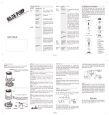
Sources of CO
Sources of CO include:
To correct stationary situations (a) and/or (b):
• Close all windows, portlights and hatches.
• If possible, move your boat away from the source of CO.
To correct running situations (c) and/or (d):
• Trim bow down.
• Open windows and canvas.
• When possible, run boat so that prevailing winds will help dissipate exhaust.
Immediately take corrective action if CO is detected or suspected (see, Carbon Monoxide Alarm System, below).
Carbon Monoxide Alarm System
• Your boat features a carbon monoxide (CO) alarm system.
• Do not disconnect the alarm system.
• Read and understand the manufacturer’s instructions for your CO alarm system. If you did not receive an instruc-
tion manual, call (800) 383-0269 and one will be mailed to you.
• If your boat is not equipped with a carbon monoxide alarm, consider purchasing one from your dealer or marine
supply store.
What To Do If Carbon Monoxide Is Detected
• Immediately ventilate and evacuate any enclosed spaces that are occupied by people and reset your CO alarm.
• Immediately move anyone showing any symptoms of CO poisoning into fresh air.
• See a doctor if any symptoms persist. If the person is unconscious, immediately administer oxygen or CPR and
call for emergency help.
c. Running boat with
trim angle of bow
too high.
a. Using engine or generator
when boat is moored in a
confined space.
b. Mooring close to
another boat that
is using its engine,
generator or any
other CO source.
d. Running boat with-
out through ventila-
tion (station wagon
effect).

6
Ciera 22’ to 28’ Cruisers • Owner’s Manual Supplement
Chapter 2: Components/Systems
Electrical System
We strongly recommend that you read and understand the Electrical Section of the Owner’s Manual.
DANGER
!
EXTREME FIRE/EXPLOSION HAZARD!
• To minimize the risks of fire and explosion, NEVER install knife switches or other arcing
devices in the fuel compartments.
• NEVER substitute automotive parts for marine parts. Electrical, ignition and fuel system
parts were designed and manufactured to comply with rules and regulations that minimize
risks of fire and explosion.
• DO NOT modify the electrical systems or relevant drawings.
• Only qualified personnel should install batteries and/or perform electrical system
maintenance.
•
••
• Insure that all battery switches are in the OFF position before performing any work in the
engine spaces.
WARNING
FIRE/EXPLOSION HAZARD!
• Fuel fumes are heavier than air and will collect in the bilge areas where they can be acci-
dently ignited. Visually and by smell (sniff test), check the engine and fuel compartments for
fumes or accumulation of fuel. Operate the bilge blower for at least four minutes prior to
engine starting, electrical system maintenance or activation of electrical devices.
• Minimize the danger of fire and explosion by not exposing batteries to open flame or sparks.
It is also important that no one smoke anywhere near the batteries.
!
CAUTION
SHOCK/ELECTRICAL SYSTEM DAMAGE HAZARD!
• Never disconnect the battery cables while the engine is running as this can cause damage to
your boat’s electrical system components.
• The battery charging systems (alternator and, if applicable, battery charger) installed on
your boat are designed to charge conventional lead-acid batteries. Before installing gel-cell
or other new technology batteries, consult with the battery manufacturer about charging
system requirements.
!
NOTICE
• Electrical connections are susceptible to corrosion. Minimize electrical problems due to cor-
rosion by keeping all exposed electrical connections clean and protected with with a spray-
on protectant such as Corrosion Guard
®
.
• VOLTAGES - All boats use either 110-volt AC/60 Hertz, 240-volt AC/60 Hertz or 220-volt
AC/50 Hertz single phase systems, and 12-volt DC or 24-volt DC. Electrical distribution
panels are labeled with voltage and frequency of AC and DC.

Ciera 22’ to 28’ Cruisers • Owner’s Manual Supplement CHAPTER 2: COMPONENTS/SYSTEMS
7
12 Volt DC System - Fuses and Circuit Breakers
Both the engine and accessory circuits are protected by a large circuit breaker located on the engine. In addition, a
fuse block for branch accessory circuits is located behind the helm panel. Wires are color-coded to indicate which
accessory each fuse services. Some items, such as radios and bilge pumps, may be fused individually at the unit.
Autofloat switches are fused at the battery.
Battery Charger
Your boat may be equipped with a battery charger. Please refer to the manufacturer’s operating instructions included
in the boat’s owner’s packet. The battery charger operates when AC dockside power is connected and the battery
charger circuit breaker is ON. The battery charger will charge batteries regardless of the battery switch position.
Shore Power/110 Volt AC System
Your boat may be equipped with an AC system. AC systems are energized by dockside shore power. Standard dock-
side receptacles and cords provided are rated at 30 amps. Since some shore installations do not have 30 amp service,
we recommend the purchase of 15 amp and 20 amp adapters. Note: When 15 amp or 20 amp adapters are used there
will be a corresponding drop in supplied AC power.
CAUTION
!
The battery charger is designed to charge conventional lead-acid batteries. Before installing
gel-cell or other new technology batteries, consult with the battery manufacturer about charg-
ing system requirements.
DANGER
!
FIRE/EXPLOSION/SHOCK HAZARD!
• To minimize shock and fire hazard, DO NOT modify electrical systems or relevant
drawings.
• DO NOT alter shore power connectors and use only compatible connectors.
• Only qualified personnel should install batteries and/or perform electrical
system maintenance.
CAUTION
SHOCK/ELECTRICAL SYSTEM DAMAGE HAZARD!
• Never connect dockside power to your boat outside North America unless you have pur-
chased the International electrical conversion option, which is rated for 220-volt/50 Hertz.
North American systems are rated for 110-volt/60 Hertz power.
• Use double insulated or three-wire protected electrical appliances when possible.
!
NOTICE
When using shore power, the simultaneous operation of several AC accessories can result in an
overloaded circuit. It may be necessary to turn off one accessory while operating another.

CHAPTER 2: COMPONENTS/SYSTEMS Ciera 22’ to 28’ Cruisers • Owner’s Manual Supplement
8
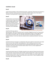
On boats with a single dock-
side inlet, check for proper
polarity as outlined in the pre-
vious warning. Activate the
AC system by first turning on
the master breaker, then each
individual component breaker
as required.
On boats with dual dockside
inlets, check for proper polar-
ity as outlined in the previous
warning. Each dockside inlet
is labeled inside the weather-
proof cover, line 1 or line 2,
which corresponds to the line
each operates on the AC mas-
ter panel. This system is
designed so that each line
operates independent of each
other. Activate the AC system
by first turning on the master
breakers, then each individual
component as required.
WARNING
FIRE/EXPLOSION/SHOCK/ELECTRICAL SYSTEM
DAMAGE HAZARD!
Before connecting to shore power, all breakers and switches on the AC master panel must be in
the OFF position. Always attach the shore power cord to the boat inlet first, then to the dock
connection, thereby avoiding accidental submersion of the “HOT” cord into the water. To dis-
connect, first remove the dock connection before removing the cord from the boat.
!
WARNING
FIRE/EXPLOSION/SHOCK/ELECTRICAL SYSTEM
DAMAGE HAZARD!
Monitor the electrical control panel’s polarity indicators when connecting shore power to your
boat. A GREEN
light illuminating after the power cord is plugged into the boat’s external
power receptacle indicates acceptable electrical power in which you may energize the main
breaker switches. A RED
light, however, indicates reversed polarity, which could cause electri-
cal system damage and possibly electrical shock injuries. In this case, DO NOT energize the
main breaker switches. Instead, immediately disconnect the shore power cord (always from the
dockside outlet first) and notify marina management.
!
TYPICAL
SHORE POWER
RECEPTACLE
MASTER BREAKERS
CAUTION
!
WATER HEATER DAMAGE HAZARD! DO NOT energize the AC water
heater electrical circuit until the heater is completely filled with water. Even
momentary operation in a dry tank will damage the heating elements. War-
ranty replacements will not be made on elements or tank damaged in this
manner. The tank is full if water flows from the tap when the hot water is
turned on in the galley.
TYPICAL AC
POWER PANEL

Ciera 22’ to 28’ Cruisers • Owner’s Manual Supplement CHAPTER 2: COMPONENTS/SYSTEMS
9
Fresh Water System
Fresh water systems are available on some models. These pressure-type (demand) systems operate when the water
pump switch (located near the sink in the cuddy cabin) is in the ON position. Turn the pump switch OFF when the
boat is not in use and when the water tank is empty.
Stored water can become stagnant and distasteful. Pump the water tank dry before leaving your boat unattended for
long periods of time. Occasionally you may want to disinfect your water system. Ask your selling dealer about avail-
able treatments and procedures.
Your boat may be equipped with a shower. Please read and follow the manufacturer’s operating instructions supplied
in the owner’s packet.
Water Heater
Your boat may come equipped with a water heater. Be sure to refer to the manufacturer’s operating instructions sup-
plied in the owner’s packet. The water heater is connected to the AC power system. If your boat is equipped with
optional freshwater engine cooling, the coolant from the closed engine cooling system may be circulated through the
hot water tank for heating of potable water.
110-Volt AC/12-Volt DC Refrigerator
Your boat may come equipped with a 110-volt AC/12-volt DC refrigerator. Please refer to the manufacturer’s instruc-
tions included in the boat’s owner’s packet.The refrigerator operates on 110-volt AC and 12-volt DC power. When
the 110-volt AC system is not hooked up to an AC source, the refrigerator operates on 12-volts DC. When a 110-volt
AC source is supplied by dockside power and the AC refrigerator breaker is ON, the refrigerator automatically
switches to 110-volt AC.
CAUTION
WATER HEATER DAMAGE HAZARD! DO NOT energize the AC water heater electrical cir-
cuit until the heater is completely filled with water. Even momentary operation in a dry tank
will damage the heating elements. Warranty replacements will not be made on elements or tank
damaged in this manner. The tank is full if water flows from the tap when the hot water is
turned on in the galley.
!
NOTICE
The refrigerator has the heaviest continuous draw on the 12-volt system. In less than 24 hours,
the refrigerator can render a 100-amp battery useless for engine starting. For this reason, it is
recommended that when operating on 12-volts, the cold setting on the refrigerator should not
be set higher than position two (2). It is also advisable to turn off your refrigerator at night or
when not in use. If you are going to be out for more than one day and cannot connect to dock-
side power, you should plan to run the engine each day to maintain a charged battery.

CHAPTER 2: COMPONENTS/SYSTEMS Ciera 22’ to 28’ Cruisers • Owner’s Manual Supplement
10
Alcohol or Alcohol/Electric Stove
Operating instructions for the alcohol or alcohol/electric stove can be found in the boat’s owner’s packet. Carefully
read and follow the manufacturer’s operating instructions and warnings before using the stove.
Air Conditioning (Optional)
Your boat may be equipped with an optional air conditioning system. Please refer to the manufacturer’s operating
instructions included in your boat’s owner’s packet.
FIRE HAZARD - Reduce the possibility of fire by removing all combustible materials away
from the stove before/during use.
WARNING
!
FIRE/PERSONAL INJURY HAZARD - Before each use of the 2858 (EC) galley stove, the lower
helm seat’s back rest MUST be lowered into the counter top position to reduce the possibility of
fire or injury (see drawing below).
WARNING
!
LOWER
HELM
HELM SEAT
LOWERED IN
COUNTER TOP
POSITION
STOVE
HELM SEAT; RAISED IN
2858 (EC) GALLEY
BACK REST POSITION

Ciera 22’ to 28’ Cruisers • Owner’s Manual Supplement CHAPTER 2: COMPONENTS/SYSTEMS
11
Navigation and Interior Lights
We strongly recommend that you understand navigation light usage by reading the navigation section of the Owner’s
Manual. The navigation and interior lights supplied with your boat are of top quality, but you should be aware that
failure may periodically occur for a variety of reasons:
1. There may be a blown fuse (Replace the fuse in the switch panel).
2. The bulb may be burned out (Carry spare bulbs for replacement).
3. The bulb base may be corroded (Clean the base periodically and coat it with non-conductive grease).
4. A wire may have come loose or may be damaged (Repair as required).
Compass
Your boat may come equipped with a compass. Carefully read and follow the manufacturer’s calibration and operat-
ing instructions provided in the boat’s owner’s packet.
Depth Finder
Your boat may come equipped with a depth finder. It will provide you with measurements of water depth beneath the
boat. In many cases it may help you locate schools of fish. We suggest that you read the manufacturer’s owner’s
operating instructions included in the boat’s owner’s packet before using the unit.
CAUTION
• Avoid the storage of gear where it would block navigation lights from view.
• Prolonged operation of cabin interior lights (overnight) will result in a drained battery. Be
conservative in the use of battery power.
!
DO NOT use the depth finder as a navigational aid to prevent collision, grounding, boat dam-
age or personal injury. When the boat is moving, submerged objects will not be seen until they
are already under the boat. Bottom depths may change too quickly to allow time for the boat
operator to react. If you suspect shallow water or submerged objects, operate the boat at very
slow speeds.
WARNING
!

CHAPTER 2: COMPONENTS/SYSTEMS Ciera 22’ to 28’ Cruisers • Owner’s Manual Supplement
12
Portable toilet
Your boat may come equipped with a portable toilet. Be sure to read and carefully follow the manufacturer’s operat-
ing instructions included in your boat’s owner’s packet.
Marine Head with Holding Tank
Your boat may come equipped with with a marine head and holding tank. Be sure to follow the manufacturer’s oper-
ating instructions included in the boat’s owner’s packet.
Seawater is used to flush waste from the toilet into the holding tank. The holding tank is plumbed to a waste fitting on
the deck for use at a dockside pump-out station, and to a macerator pump so that waste may be pumped overboard
(where regulations permit). The switch for the macerator is usually located at the helm station.
If at any time you are unable to pump water into the bowl, the probable cause is debris in the pump diaphragm. To
remedy this, shut the inlet seacock and dismantle the pump. The pump is generally held together with six screws. The
design is simple and the problem will be obvious when the pump body is split open.
To winterize the toilet, shut off the intake valve and pump until the bowl is dry. Remove the drain plug in the base and
pump again to remove all water. Do not fill the bowl with antifreeze. The inlet seacock should be left closed while the
boat is underway, or whenever the boat is left moored in the water.

Ciera 22’ to 28’ Cruisers • Owner’s Manual Supplement CHAPTER 2: COMPONENTS/SYSTEMS
13
Fuel System
Fuel Fills and Vents
Fuel fills are located either on the aft deck or on the side decks adjacent to the aft cockpit. Fuel receptacle caps are
marked “Diesel” or “GAS”. Fuel vents are normally located in the hull or transom below and in the same general area
as the fill. If you experience difficulty filling the fuel tank, check to see that the fuel fill and vent lines are free of
obstructions and kinks.
Anti-siphon Valve
Your boat may be equipped with an anti-siphon valve, which is an integral part of the barb fitting on the fuel tank in
which the neoprene fuel line attaches. The valve is spring loaded and is opened by fuel pump vacuum. These valves
will prevent fuel from siphoning from the tank in the event of a fuel line rupture.
WARNING
FIRE/EXPLOSION HAZARD - It is very important that the fuel system be
inspected thoroughly the first time it is filled and at each subsequent filling. For
your safety and the safety of your passengers, the fueling instructions in the
Owner’s Manual must be carefully followed.
!
NOTICE
Air in the diesel supply system (if equipped) can stop an engine or severely restrict perfor-
mance. If you suspect air in your diesel fuel lines, refer to your engine owner’s manual for
detailed instructions on how to “bleed” the system.
CAUTION
Avoid the storage or handling of gear near the fuel lines, fittings and tank.
!
NOTICE
If an engine running problem is diagnosed as fuel starvation, check the anti-siphon valve. In the
event the valve is stuck or clogged, it should be changed or replaced while the engine is shut down.
Under NO circumstances should the anti-siphon valve be removed, except in an emergency.

CHAPTER 2: COMPONENTS/SYSTEMS Ciera 22’ to 28’ Cruisers • Owner’s Manual Supplement
14
Fuel Filters
All tanks are equipped with a fine mesh screen filter on the fuel pickup tube (located inside or on the outside of the
tank) to the fuel line fitting. In addition, when supplied by the engine manufacturer, and additional filter is installed
on the engine. Fuel filters should be replaced periodically to ensure they remain clean and free of debris. Consult
your selling dealer or local marina concerning fuel additives that help to prevent fungus or buildup in your fuel tanks.
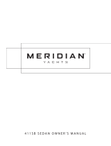
Bilge Blower
The bilge blower removes fumes
from the engine compartment and
draws fresh air into the compartment
through the deck vents. To ensure
fresh air circulation, operate the bilge
blower for at least four minutes
before starting the engine, during
starting, and while operating the boat
below cruising speed.
FUEL
FUEL FILL
DECK FITTING
FUEL
FILTER
FUEL
PICKUP
FUEL
RETURN
TYPICAL DIESEL FUEL SYSTEM
TANK
VENT
FUEL
TANK
FUEL TANK
FUEL TANK VENT
DECK FITTING,
FUEL FILL
FUEL FEED
HOSE
TYPICAL GAS FUEL SYSTEM
TYPICAL BILGE
BLOWER SYSTEM
WARNING
!
Operation of the blower system is NOT A GUARANTEE that explosive fumes have
been removed. If you smell any fuel, DO NOT start the engine. If the engine is
already running, immediately shut off the engine and all electrical accessories.
Investigate immediately. DO NOT obstruct or modify the ventilation system.
Page is loading ...
Page is loading ...
Page is loading ...
Page is loading ...
Page is loading ...
Page is loading ...
Page is loading ...
Page is loading ...
Page is loading ...
Page is loading ...
Page is loading ...
Page is loading ...
Page is loading ...
Page is loading ...
Page is loading ...
Page is loading ...
Page is loading ...
Page is loading ...
Page is loading ...
Page is loading ...
Page is loading ...
Page is loading ...
Page is loading ...
Page is loading ...
Page is loading ...
Page is loading ...
Page is loading ...
Page is loading ...
Page is loading ...
Page is loading ...
Page is loading ...
Page is loading ...
Page is loading ...
Page is loading ...
Page is loading ...
Page is loading ...
Page is loading ...
Page is loading ...
Page is loading ...
Page is loading ...
Page is loading ...
Page is loading ...
Page is loading ...
Page is loading ...
Page is loading ...
Page is loading ...
Page is loading ...
Page is loading ...
-
 1
1
-
 2
2
-
 3
3
-
 4
4
-
 5
5
-
 6
6
-
 7
7
-
 8
8
-
 9
9
-
 10
10
-
 11
11
-
 12
12
-
 13
13
-
 14
14
-
 15
15
-
 16
16
-
 17
17
-
 18
18
-
 19
19
-
 20
20
-
 21
21
-
 22
22
-
 23
23
-
 24
24
-
 25
25
-
 26
26
-
 27
27
-
 28
28
-
 29
29
-
 30
30
-
 31
31
-
 32
32
-
 33
33
-
 34
34
-
 35
35
-
 36
36
-
 37
37
-
 38
38
-
 39
39
-
 40
40
-
 41
41
-
 42
42
-
 43
43
-
 44
44
-
 45
45
-
 46
46
-
 47
47
-
 48
48
-
 49
49
-
 50
50
-
 51
51
-
 52
52
-
 53
53
-
 54
54
-
 55
55
-
 56
56
-
 57
57
-
 58
58
-
 59
59
-
 60
60
-
 61
61
-
 62
62
-
 63
63
-
 64
64
-
 65
65
-
 66
66
-
 67
67
-
 68
68


Bayliner Ciera 2859 Express SC Owner's manual
- Type
- Owner's manual
Ask a question and I''ll find the answer in the document
Finding information in a document is now easier with AI
Related papers
-
Bayliner 1998 Ciera 22-28 Owner's manual
-
-
-
-
-
-
-
-
-
Other documents
-
 boatcommand BC-4001 User manual
-
 Maxum 2700 SE SPORT EXPRESS CRUISER Owner's Manual Supplement
-
 SEAFLO SFBP1-G350-01 User manual
-
 Clean Dump CDPU Installation guide
-
 Meridian Yachts 411SB Sedan Owner's manual
-
 Maxum 4100 SCA Sportyacht Specification
-
 Liberty Pumps ASCENTII-RSW Specification
-
Danfoss OAB Office Alarm Box Installation guide
-
Dometic Self-Contained Air Conditioning Systems DCG, DCMG, DCU, DLM, DLU, DMT, DTG, DTU, ECD, MCS Installation guide
-
Saniflo 011 Dimensions Guide


