
DRM100 Designer Reference Manual
Devices Supported:
56F801X
Document Number: DRM100
Rev. 0
06/2008


Contents
Chapter 1
Introduction
1.1 Introduction ............................................................................................................................. 9
1.2 Freescale Digital Signal Controller Advantages and Features ............................................. 10
Chapter 2
SR Motor Control Theory
2.1 Two Phase Switch Reluctance (SR) Motor........................................................................... 13
2.2 Digital Control of an SR Motor ..............................................................................................15
2.3 Voltage and Current Control of SR Motors ........................................................................... 17
2.3.1 Voltage Control of an SR Motor ................................................................................... 17
2.3.2 Sensorless Position Estimation Using Phase Current Peak Detection ........................ 19
Chapter 3
System Concept
3.1 System Specification............................................................................................................. 21
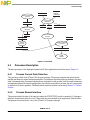
3.2 Sensorless Drive Concept ....................................................................................................22
3.3 Control Process .................................................................................................................... 22
3.4 System Blocks Description ...................................................................................................23
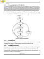
3.4.1 Sensing of Phase Currents and DC-Bus Voltage......................................................... 23
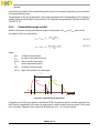
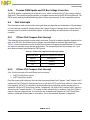
3.4.2 Phase Current Peak Detection..................................................................................... 25
3.4.3 SR Motor Start-Up (Patent No. US6448736 B1).......................................................... 27
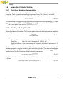
3.4.4 Commutation angle control .......................................................................................... 28
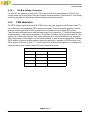
3.4.5 PWM Modulation .......................................................................................................... 29
Chapter 4
Hardware
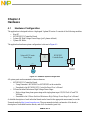
4.1 Hardware Configuration........................................................................................................ 31
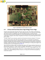
4.2 MC56F8013/23 Controller Board.......................................................................................... 32
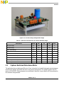
4.3 3-Phase Switched Reluctance High Voltage Power Stage................................................... 33
4.4 2-phase Switched Reluctance Motor .................................................................................... 34
Chapter 5
Software Design
5.1 Introduction ........................................................................................................................... 35
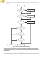
5.2 Main Software Flow Chart..................................................................................................... 35
5.3 Data Flow.............................................................................................................................. 36
5.4 Processes Description .......................................................................................................... 37
5.4.1 Process Current Peak Detection .................................................................................. 37
5.4.2 Process Manual Interface............................................................................................. 37
5.4.3 Process Application State Machine.............................................................................. 38
5.4.4 Process Ramp..............................................................................................................38
5.4.5 Process Commutation .................................................................................................. 38
5.4.6 Process PWM Update and DC Bus Voltage Correction............................................... 39

5.5 Fast Interrupts....................................................................................................................... 39
5.5.1 QTimer Ch3 Compare Fast Interrupt............................................................................ 39
5.5.2 QTimer Ch2 Compare Fast Interrupt............................................................................ 39
5.6 Application Variables Scaling................................................................................................ 40
5.6.1 Fractional Numbers Representation............................................................................. 40
5.6.2 Scaling of Analog Quantities ........................................................................................ 40
5.7 Constant Calculation............................................................................................................. 41
5.7.1 Alignment Constants .................................................................................................... 41
5.7.2 Start Up Constants ....................................................................................................... 41
5.7.3 Current Measurement Constants ................................................................................. 42
5.7.4 Voltage Measurement Constants ................................................................................. 43
5.7.5 SR Motor Related Constants........................................................................................ 43
5.8 Software Customizing for another SR Motor ........................................................................ 44
5.9 Real Figures taken by the Oscilloscope................................................................................ 44
Chapter 6
Application Setup
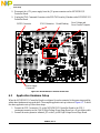
6.1 MC56F8013 Controller Board Setup..................................................................................... 47
6.2 Application Hardware Setup ................................................................................................. 48
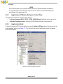
6.3 Application Software Setup................................................................................................... 49
6.3.1 Application Software Files ............................................................................................ 49
6.3.2 Application PC Master Software Control Files ............................................................. 50
6.3.3 Application Build........................................................................................................... 50
6.3.4 Programming the MCU................................................................................................. 51
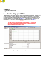
Chapter 7
Application Control
7.1 Operating of High Speed SR Drive ....................................................................................... 53
Appendix A
References
Appendix B
Glossary of Abbreviations

Figures
2-Phase 4/2 SR Motor ................................................................................................................ 13
Aligned/Unaligned Rotor Position of a 2-Phase SR motor.......................................................... 14
Phase Energizing........................................................................................................................ 15
2-Phase SR Power Stage ........................................................................................................... 16
Soft Switching and Hard Switching............................................................................................. 17
Voltage Control Technique ......................................................................................................... 18
Voltage Control Technique - Voltage and Current Profiles ......................................................... 18
Rotor Position at Phase Current Peak........................................................................................ 19
System Concept.......................................................................................................................... 23
Phase Current Circuit.................................................................................................................. 24
Phase Current Sampling............................................................................................................. 25
The Current Peak Detection Algorithm ....................................................................................... 26
Start Up Algorithm....................................................................................................................... 27
Commutation angle Control ........................................................................................................ 28
Hardware System Configuration................................................................................................. 31
MC56F8013/23 Controller Board Top View................................................................................ 33
3-Phase SR High Voltage Power Stage ..................................................................................... 34
Main Software Flow Chart........................................................................................................... 36
Data flow..................................................................................................................................... 37
Application State Machine .......................................................................................................... 38
Commutation angles definition.................................................................................................... 44
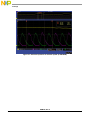
SR Motor Start Up....................................................................................................................... 45
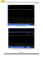
SR motor operation at low speed (5700 RPM) ........................................................................... 45
SR motor operation at maximal speed (61 000 RPM) ................................................................ 46
MC56F8013/23 Controller Board View ....................................................................................... 48
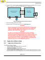
Demo Application Connection Overview..................................................................................... 49
Execute Make Command............................................................................................................50
Execute Debug Command.......................................................................................................... 51
High Speed SR Motor Project in FreeMaster.............................................................................. 53
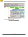
Setting FreeMASTER Communication ....................................................................................... 54


Tables
Memory Configuration................................................................................................................. 10
PWM Output Setting ................................................................................................................... 29
Electrical Characteristics of 3-Phase SR Power Stage............................................................... 34
QTimer Ch3 Compare Fast Interrupt routines ............................................................................ 39
MC56F8013/23 Controller Board Jumper Setting....................................................................... 47


DRM100, Rev. 0
Freescale Semiconductor 9
Chapter 1
Introduction
1.1 Introduction
This designer reference manual describes a sensorless high speed Switch Reluctance (SR) motor drive,
where the rotor position detection is based on phase current peak detection. The presented high speed SR
drive is targeted mainly at vacuum cleaners and other appliance and industry applications, which can
benefit from small motor size and high speed. Usage of the Freescale Semiconductor MC56F8013 device
ensures cost-effective implementation for this type of motor control application.
The switched reluctance motor brings advantages in both cost and reliability over other types of adjustable
speed drives, such as a simple mechanical construction, high efficiency, high power density and so on. On
the other hand, large torque ripple, due to double saliency construction, limits usage of the switch
reluctance motor in many applications. One of the SR motor advantages is operation at high speed
(> 50 000 RPM). It results in a smaller motor for a given output power and reduces the size and weight of
the target application. A typical application which can benefit from this feature, is a vacuum cleaner. The
high speed SR motor makes the vacuum cleaner smaller and lighter, and the noise generated by torque
ripple is comparable with other types of motors.
To run an SR motor properly, the position of the rotor has to be known. The control of an SR motor with
a position sensor is quite tricky and the sensor increases the total system cost and decreases overall
reliability of the drive. Therefore, there is a huge effort to implement control methods for SR motor without
any position sensors. The presented technique is based on phase current peak detection. The phase current
peak corresponds to a certain position of the motor. If this peak is detected, the position of the rotor can be
determined. The phase current peak is evaluated fully by software implemented on the Freescale digital
signal controller MC56F8013 dedicated to various motor control applications. The application described
hereafter covers the following features of the SR motor drive:
• High speed 2-phase SR motor sensorless control based on current peak detection
• Designed to fit vacuum cleaner applications
• Capable of running an SR motor at more than 100 000 RPM (tested with an SR motor designed for
60 000 RPM)
• Single direction of rotation given by asymmetric construction of a 2-phase SR motor
• Speed open loop control
• Start up from any position using alignment and patented algorithm (Patent No. US6448736 B1)
• Start up time and maximal speed depends on the SR motor parameters

Introduction
DRM100, Rev. 0
10 Freescale Semiconductor
1.2 Freescale Digital Signal Controller Advantages and Features
The Freescale MC56F80xx family is well suited to digital motor control, combining the DSP’s calculation
capability with the MCU’s controller features on a single chip. These hybrid controllers offer many
dedicated peripherals such as pulse width modulation (PWM) modules, analog-to-digital converters
(ADC), timers, communication peripherals (SCI, SPI, I
2
C), and on-board Flash and RAM.
The MC56F80xx family members provide the following peripheral blocks:
• One PWM module with PWM outputs, fault inputs, fault-tolerant design with dead time insertion,
supporting both centre-aligned and edge-aligned modes
• 12-bit ADC, supporting two simultaneous conversions; ADC and PWM modules can be
synchronized
• One dedicated 16-bit general purpose quad timer module
• One serial peripheral interface (SPI)
• One serial communications interface (SCI) with LIN slave functionality
• One inter-integrated circuit (I
2
C) port
• On-board 3.3V to 2.5V voltage regulator for powering internal logic and memories
• Integrated power-on reset and low voltage interrupt module
• All pins multiplexed with general purpose input/output (GPIO) pins
• Computer operating properly (COP) watchdog timer
• External reset input pin for hardware reset
• JTAG/On-Chip Emulation (OnCE™) module for unobtrusive, processor-speed-independent
debugging
• Phase-locked loop (PLL) based frequency synthesizer for the hybrid controller core clock, with
on-chip relaxation oscillator
The two-phase SR control benefits greatly from the flexible PWM module, fast ADC, quad timer module
and interrupt controller module.
The PWM block has the following features:
• Three complementary PWM signal pairs, six independent PWM signals (or a combination)
• Complementary channel operation features
• Independent top and bottom dead time insertion
• Separate top and bottom pulse width correction via current status inputs or software
• Separate top and bottom polarity control
• Edge-aligned or centre-aligned PWM reference signals
• 15-bit resolution
• Half-cycle reload capability
• Integral reload rates from one to sixteen periods
• Mask/swap capability
• Individual, software-controlled PWM output
• Programmable fault protection
Table 1-1. Memory Configuration
Memory Type MC56F8013 MC56F8023
Program Flash 16 KByte 32 KByte
Unified Data/Program RAM 4 KByte 8 KByte

Introduction
DRM100, Rev. 0
Freescale Semiconductor 11
• Polarity control
• 10mA or 16mA current sink capability on PWM pins
• Write-protectable registers
The PWM offers flexibility in its configuration, enabling efficient two phase SR motor control. The
interesting features of the PWM module (from an SR motor control point of view) are the automatic copy
of duty cycle values to all value registers and the software and masks controls. This automatic copying
simplifies duty cycle control, where a single duty cycle update is necessary to update all PWM channels.
The software control is used to perform unipolar PWM generation (bottom transistor is ON during the
whole period). The last feature - mask control is used for phase commutation or disabling the inactive
phase. The PWM reload SYNC signal is generated to provide synchronization with other modules
(Quadtimers, ADC).
The ADC module has the following features:
• 12-bit resolution
• Dual ADCs per module; three input channels per ADC
• Maximum ADC clock frequency of 5.33MHz with a 187ns period
• Sampling rate of up to 1.78 million samples per second
• Single conversion time of 8.5 ADC clock cycles (8.5 x 187ns = 1.59μs)
• Additional conversion time of six ADC clock cycles (6 x 187ns = 1.125μs)
• Eight conversions in 26.5 ADC clock cycles (26.5 x 187ns = 4.97μs) using parallel mode
• Ability to use the SYNC input signal to synchronize with the PWM (provided the integration
allows the PWM to trigger a timer channel connected to the SYNC input)
• Ability to sequentially scan and store up to eight measurements
• Ability to scan and store up to four measurements on each of two ADCs operating simultaneously
and in parallel
• Ability to scan and store up to four measurements on each of two ADCs operating asynchronously
to each other in parallel
• Interrupt generating capabilities at the end of a scan when an out-of-range limit is exceeded and on
a zero crossing
• Optional sample correction by subtracting a pre-programmed offset value
• Signed or unsigned result
• Single-ended or differential inputs
• PWM outputs with hysteresis for three of the analog inputs
The application uses the ADC block in simultaneous mode scan. It is synchronized to the PWM pulses.
This configuration allows the simultaneous conversion of the DC-bus current and voltage within the
required time.
The quad timer is an extremely flexible module, providing all required services relating to time events. It
has the following features:
• Four 16-bit counters/timers
• Count up/down
• Counters are cascadable
• Programmable count modulus
• Maximum count rate equal to the peripheral clock/2, when counting external events
• Maximum count rate equal to the peripheral clock/1, when using internal clocks

Introduction
DRM100, Rev. 0
12 Freescale Semiconductor
• Count once or repeatedly
• Counters are preloadable
• Counters can share available input pins
• Each counter has a separate prescaler
• Each counter has capture and compare capability
The application uses four channels of the quad timer for:
• One channel for PWM-to-ADC synchronization
• One channel for motor commutation
• One channel for system time base (5ms period)
The interrupt controller (ITCN) has the following features:
• Four programmable priority levels for each IRQ
• Two programmable Fast Interrupts
• Notifies the SIM module to restart clocks out of Wait and Stop modes
• Ability to drive the initial address on the address bus after reset
Fast interrupts are used for ADC measurement and motor commutation. This minimizes overhead caused
by frequently calling the interrupt routine. (the ADC sensing interrupt is called every 4.4 μs).

DRM100, Rev. 0
Freescale Semiconductor 13
Chapter 2
SR Motor Control Theory
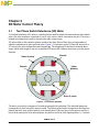
2.1 Two Phase Switch Reluctance (SR) Motor
A Switched Reluctance (SR) motor is a rotating electric machine where both stator and rotor have salient
poles. The stator winding is comprised of a set of coils, each of which is wound on one pole. The rotor is
created from lamination in order to minimize the eddy-current losses.
SR motors differ in the number of phases wound on the stator. Each of them has a certain number of
suitable combinations of stator and rotor poles. Figure 2-1 illustrates a typical 2-Phase SR motor with a
4/2 (stator/rotor) pole configuration and a stepped gap. The stepped gap is used due to eliminate dead
zones, where motor torque is zero at a symmetrical SR motor and it ensures motor start up in the proper
direction.
Figure 2-1. 2-Phase 4/2 SR Motor
The motor is excited by a sequence of current pulses applied at each phase. The individual phases are
consequently excited, forcing the motor to rotate. The current pulses need to be applied to the respective
phase at the exact rotor position relative to the excited phase. When any pair of rotor poles is exactly in
line with the stator poles of the selected phase, the phase is said to be in an aligned position, i.e., the rotor
Rotor (2 poles)
Stator
Winding
Phase A
Phase B
Stator (4 poles)

SR Motor Control Theory
DRM100, Rev. 0
14 Freescale Semiconductor
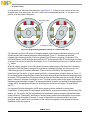
is in the position of maximal stator inductance (see Figure 2-2). If the axis of the rotor is in line with
interpolar axis of the stator poles, the rotor is said to be in an unaligned position, i.e., the rotor is in a
position of minimal stator inductance.
Figure 2-2. Aligned/Unaligned Rotor Position of a 2-Phase SR motor
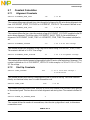
The inductance profile of SR motors is triangular shaped, with maximum inductance when it is in an
aligned position and minimum inductance when unaligned. Figure 2-3 illustrates the idealized
triangular-like inductance profile of both two phases of an SR motor with phase A highlighted. The
individual Phases A and B are shifted electrically by 180
o
relative to each other. When the respective phase
is powered, the interval is called the dwell angle - θ
dwell
. It is defined by the turn-on θ
on
and the turn-off
θ
off
angles.
When the voltage is applied to the stator phase, the motor creates torque in the direction of increasing
inductance. When the phase is energized in its minimum inductance position, the rotor moves to the
forthcoming position of maximal inductance. The movement is defined by the magnetization
characteristics of the motor. A typical current profile for a constant phase voltage is shown in Figure 2-3.
For a constant phase voltage the phase current has its maximum in the position when the inductance starts
to increase. This corresponds to the position where the rotor and the stator poles start to overlap. When the
phase is turned off, the phase current falls to zero. The phase current present in the region of decreasing
inductance generates negative torque. The torque generated by the motor is controlled by the applied phase
voltage and by the appropriate definition of switching turn-on and turn-off angles. For more details,
see [12].
As is apparent from the description, the SR motor requires position feedback for motor phase
commutation. In many cases, this requirement is addressed by using position sensors, like encoders, Hall
sensors, etc. The result is that the implementation of mechanical sensors increases costs and decreases
system reliability. Traditionally, developers of motion control products have attempted to lower system
costs by reducing the number of sensors. A variety of algorithms for sensorless control have been
developed, most of which involve evaluation of the variation of magnetic circuit parameters that are
dependent on the rotor position.
Aligned Position
Unaligned Position

SR Motor Control Theory
DRM100, Rev. 0
Freescale Semiconductor 15
Figure 2-3. Phase Energizing
The motor itself is a low cost machine of simple construction. Since high-speed operation is possible, the
motor is suitable for high speed applications, like vacuum cleaners, fans, white goods, etc. As discussed
above, the disadvantage of the SR motor is the need for shaft-position information for the proper switching
of individual phases. Also, the motor structure causes noise and torque ripple. The greater the number of
poles, the smoother the torque ripple, but motor construction and control electronics become more
expensive. Torque ripple can also be reduced by advanced control techniques such as phase current
profiling. The detail mathematical description of the SR motor can be seen in [11].
2.2 Digital Control of an SR Motor
The SR motor is driven by voltage strokes coupled with the given rotor position. The profile of the phase
current together with the magnetization characteristics define the generated torque and thus the speed of
the motor. Due to this fact, the motor requires electronic control for operation. Several power stage
topologies are being implemented, according to the number of motor phases and the desired control
algorithm. The particular structure of the SR power stage structure defines the freedom of control for an
individual phase.
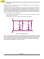
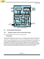
A power stage with two independent power switches per motor phase is the most used topology. Such a
power stage for 3-Phase SR motors is illustrated in Figure 2-4. It enables control of the individual phases
fully independent of each other and thus permits the widest freedom of control. Other power stage
topologies share some of the power devices for several phases, thus saving on power stage cost, but with
these the phases cannot be fully independently controlled. Note that this particular topology of SR power
Unaligned
Stator Phase A
Rotor
L
A
Phase A
Energizing
Aligned Aligned
q
on_phA
q
off_phA
position / time
position / time
q
dwell
i
phA
L
B

SR Motor Control Theory
DRM100, Rev. 0
16 Freescale Semiconductor
stage is fault tolerant -- in contrast to power stages of AC induction motors -- because it eliminates the
possibility of a rail-to-rail short circuit.
During normal operation, the electromagnetic flux in an SR motor is not constant and must be built for
every stroke. In the motoring period, these strokes correspond to the rotor position when the rotor poles
are approaching the corresponding stator pole of the excited phase. In the case of Phase A, shown in
Figure 2-1, the stroke can be established by activating the switches Q1 and Q2. At low-speed operation the
Pulse Width Modulation (PWM), applied to the corresponding switches, modulates the voltage level.
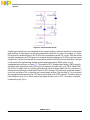
Two basic switching techniques can be applied:
• Soft switching - where one transistor is left turned-on during the whole commutation period and
PWM is applied to the other one
• Hard switching - where PWM is applied to both transistors simultaneously
Figure 2-4. 2-Phase SR Power Stage
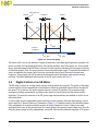
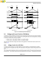
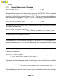
Figure 2-5 illustrates both soft and hard switching PWM techniques. The control signals for the upper and
the lower switches of the above-described power stage define the phase voltage and thus the phase current.
The soft switching technique generates lower current ripple compared to the hard switching technique.
Also, it produces lower acoustic noise and less EMI. Therefore, soft switching techniques are often
preferred for motoring operations. For more details, see [12].
Phase B
DC Voltage
Q3
Q4
D1
PWM_Q1
PWM_Q4
+
Cap
GND
Phase A
Q2
PWM_Q2
D2
PWM_Q3
D2
D1Q1

SR Motor Control Theory
DRM100, Rev. 0
Freescale Semiconductor 17
Figure 2-5. Soft Switching and Hard Switching
2.3 Voltage and Current Control of SR Motors
A number of control techniques for SR motors exist. They differ in the structure of the control algorithm
and in position evaluation. Two basic techniques for controlling SR motors can be distinguished, according
to the motor variables that are being controlled:
• Voltage control - where phase voltage is a controlled variable
• Current control - where phase current is a controlled variable
The next section describes voltage control used in this application. Details about current control can be
found in [11].
2.3.1 Voltage Control of an SR Motor
In voltage control techniques, the voltage applied to the motor phases is constant during the complete
sampling period of the speed control loop. The commutation of the phases is linked to the position of the
rotor.
The voltage applied to the phase is directly controlled by a speed controller. The speed controller processes
the speed error -- the difference between the desired speed and the actual speed -- and generates the desired
Stator Poles
Rotor Poles
Unaligned Aligned
Turn On Turn Off
Inductance
Phase Voltage
Phase Current
Unaligned Aligned
Turn On Turn Off
Soft Switching Hard Switching
Position Position
Upper Switch
Lower Switch
PWM PWM
PWM
+V
DC
+V
DC
-V
DC
-V
DC

SR Motor Control Theory
DRM100, Rev. 0
18 Freescale Semiconductor
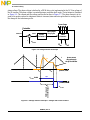
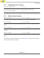
phase voltage. The phase voltage is defined by a PWM duty cycle implemented at the DC-Bus voltage of
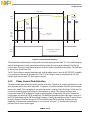
the SR inverter. The phase voltage is constant during a complete dwell angle. The technique is illustrated
in Figure 2-6. The current and the voltage profiles can be seen in Figure 2-7. The phase current is at its
peak at the position when the inductance starts to increase (stator and rotor poles start to overlap) due to
the change in the inductance profile.
Figure 2-6. Voltage Control Technique
Figure 2-7. Voltage Control Technique - Voltage and Current Profiles
Speed
Controller
PWM
Generator
ω
desired
PWM Output
Duty Cycle
Controller
ω
actual
ω
error
Power Stage
θ
on
θ
off
-
Σ
Speed
Controller
PWM
Generator
ω
desired
PWM Output
Duty Cycle
Controller
ω
actual
ω
error
Power Stage
θ
on
θ
off
-
Σ
L
θ
on
θ
off
position / time
position / time
i
ph
-U
DC-Bus
U
DC-Bus
*PWM
PWM = Speed
Controller Output
u
ph
phase current
decays through
the fly back diodes
L
θ
on
θ
off
position / time
position / time
i
ph
-U
DC-Bus
U
DC-Bus
*PWM
PWM = Speed
Controller Output
u
ph
phase current
decays through
the fly back diodes

SR Motor Control Theory
DRM100, Rev. 0
Freescale Semiconductor 19
2.3.2 Sensorless Position Estimation Using Phase Current Peak Detection
The flux linkage estimation method ranks among the most popular sensorless SR position estimation
techniques. A number of methods that use the flux linkage calculation have been developed in [11, 14, 15].
These methods calculate the actual phase flux linkage and use its relation to the reference flux linkage for
position estimation.
The main disadvantage of all these methods is that the estimation of the flux linkage is based on a precise
knowledge of the phase resistance. The phase resistance varies significantly with temperature which yields
to unwanted integration errors, especially at low speed. These integration errors create a significant
position estimation error.
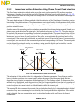
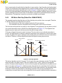
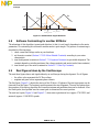
Another method for sensorless position estimation presented in this reference design manual is based on a
phase current peak detection. The principle of this method can be seen in Figure 2-8. The phase starts to
be excited at the moment corresponding to a desired current amplitude. The current begins to rise till the
position where the stator and rotor poles start to overlap. At this moment, the phase current reaches it’s
maximum. Since we know the exact position of the rotor, we can estimate rotor position based on this
current peak. If the current peak is detected, the peak time is saved. Knowing the time of two consecutive
current peaks, we can calculate the commutation period and corresponding on/off times. The current peak
can be detected by external circuitry, or, nowadays, using powerful digital signal controller, it can be
evaluated directly by software.
Figure 2-8. Rotor Position at Phase Current Peak
The advantage of this method is that it is independent of the motor parameters. Everything we need to
know is the rotor position at the current peak. Another advantage is that the current peak detection
algorithm is very simple in comparison with estimation of the flux linkage method. It allows to use this
method at very high speed, where the precision of the flux linkage estimation is low due to low number of
current samples for flux calculation. From principle of the operation, this method can be used with voltage
control only since at current control we lose information about the current peak.
The resented SR drive measures the current of the excited phase directly by the integrated analog to digital
converter. Every new current sample is evaluated by the current peak detection algorithm. If the current
peak is detected, the new commutation period is calculated together with on/off times for the next
commutation.
Just in touch
Stator Phase A
Rotor
L
A
Aligned Aligned
position / time
i
phA
L
B

SR Motor Control Theory
DRM100, Rev. 0
20 Freescale Semiconductor
Page is loading ...
Page is loading ...
Page is loading ...
Page is loading ...
Page is loading ...
Page is loading ...
Page is loading ...
Page is loading ...
Page is loading ...
Page is loading ...
Page is loading ...
Page is loading ...
Page is loading ...
Page is loading ...
Page is loading ...
Page is loading ...
Page is loading ...
Page is loading ...
Page is loading ...
Page is loading ...
Page is loading ...
Page is loading ...
Page is loading ...
Page is loading ...
Page is loading ...
Page is loading ...
Page is loading ...
Page is loading ...
Page is loading ...
Page is loading ...
Page is loading ...
Page is loading ...
Page is loading ...
Page is loading ...
Page is loading ...
Page is loading ...
Page is loading ...
Page is loading ...
Page is loading ...
Page is loading ...
-
 1
1
-
 2
2
-
 3
3
-
 4
4
-
 5
5
-
 6
6
-
 7
7
-
 8
8
-
 9
9
-
 10
10
-
 11
11
-
 12
12
-
 13
13
-
 14
14
-
 15
15
-
 16
16
-
 17
17
-
 18
18
-
 19
19
-
 20
20
-
 21
21
-
 22
22
-
 23
23
-
 24
24
-
 25
25
-
 26
26
-
 27
27
-
 28
28
-
 29
29
-
 30
30
-
 31
31
-
 32
32
-
 33
33
-
 34
34
-
 35
35
-
 36
36
-
 37
37
-
 38
38
-
 39
39
-
 40
40
-
 41
41
-
 42
42
-
 43
43
-
 44
44
-
 45
45
-
 46
46
-
 47
47
-
 48
48
-
 49
49
-
 50
50
-
 51
51
-
 52
52
-
 53
53
-
 54
54
-
 55
55
-
 56
56
-
 57
57
-
 58
58
-
 59
59
-
 60
60


NXP 56F801X Reference guide
- Type
- Reference guide
Ask a question and I''ll find the answer in the document
Finding information in a document is now easier with AI
Related papers
Other documents
-
 Funphix Orange & Yellow Balls Owner's manual
-
 Funphix FPF-G-BG Owner's manual
-
 Hey! Play! M350042 Operating instructions
-
Cypress Semiconductor CY8CKIT-037 User manual
-
Motorola MC68HC908MR32 User guide
-
-
-
Texas Instruments Sensorless Field Oriented Control:3-Phase Perm.Magnet Synch. Motors With CLA Application Note
-
NXP Semiconductors KEA128LEDLIGHTRD Installation Instructions Manual
-
Silicon Laboratories SENSORLESS-BLDC-MOTOR-RD User manual


