
56800E
16-bit Digital Signal Controllers
freescale.com
3-Phase BLDC Drive Using Variable DC Link
Six-Step Inverter
Designer Reference Manual
DRM078
Rev. 1
05/2006


3-Phase BLDC Drive Using Variable DC Link Six-Step Inverter, Rev. 1
Freescale Semiconductor 3
3-Phase BLDC Drive Using DC/DC Inverter
Designer Reference Manual
by: Jaroslav Musil
Freescale Czech Systems Laboratories
Roznov pod Radhostem, Czech Republic
To provide the most up-to-date information, the revision of our documents on the World Wide Web will be
the most current. Your printed copy may be an earlier revision. To verify you have the latest information
available, refer to:
http://www.freescale.com
The following revision history table summarizes changes contained in this document. For your
convenience, the page number designators have been linked to the appropriate location.
Revision History
Date
Revision
Level
Description
Page
Number(s)
March,
2006
0 Initial release N/A
May, 2006 1
Changed hybrid controller to digital signal controller
Changed DC/DC inverter to variable DC link six-step inverter
Minor edits to clarify Chapter 1
Renamed Section 2.4 to better reflect contents and added information at end
of section
Various
Various
7
17

Revision History
3-Phase BLDC Drive Using Variable DC Link Six-Step Inverter, Rev. 1
4 Freescale Semiconductor

3-Phase BLDC Drive Using Variable DC Link Six-Step Inverter, Rev. 1
Freescale Semiconductor 5
Table of Contents
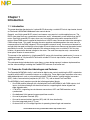
Chapter 1
Introduction
1.1 Introduction . . . . . . . . . . . . . . . . . . . . . . . . . . . . . . . . . . . . . . . . . . . . . . . . . . . . . . . . . . . . . . . . . 7
1.2 Freescale Controller Advantages and Features . . . . . . . . . . . . . . . . . . . . . . . . . . . . . . . . . . . . . 7
Chapter 2
Control Theory
2.1 BLDC Motor . . . . . . . . . . . . . . . . . . . . . . . . . . . . . . . . . . . . . . . . . . . . . . . . . . . . . . . . . . . . . . . . 11
2.2 BLDC Motor Control Using DC/DC Inverter. . . . . . . . . . . . . . . . . . . . . . . . . . . . . . . . . . . . . . . . 11
2.3 Commutation . . . . . . . . . . . . . . . . . . . . . . . . . . . . . . . . . . . . . . . . . . . . . . . . . . . . . . . . . . . . . . . 13
2.4 Speed Control . . . . . . . . . . . . . . . . . . . . . . . . . . . . . . . . . . . . . . . . . . . . . . . . . . . . . . . . . . . . . . 16
Chapter 3
System Concept
3.1 System Specification . . . . . . . . . . . . . . . . . . . . . . . . . . . . . . . . . . . . . . . . . . . . . . . . . . . . . . . . . 17
3.2 Application Description . . . . . . . . . . . . . . . . . . . . . . . . . . . . . . . . . . . . . . . . . . . . . . . . . . . . . . . 17
3.3 Control Process . . . . . . . . . . . . . . . . . . . . . . . . . . . . . . . . . . . . . . . . . . . . . . . . . . . . . . . . . . . . . 18
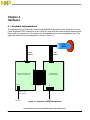
Chapter 4
Hardware
4.1 Hardware Implementation . . . . . . . . . . . . . . . . . . . . . . . . . . . . . . . . . . . . . . . . . . . . . . . . . . . . . 21
4.2 MC56F8013 Controller Board . . . . . . . . . . . . . . . . . . . . . . . . . . . . . . . . . . . . . . . . . . . . . . . . . . 22
4.3 3-Phase Power Stage with DC/DC Inverter Lite . . . . . . . . . . . . . . . . . . . . . . . . . . . . . . . . . . . . 23
4.4 Motor Specifications — Example . . . . . . . . . . . . . . . . . . . . . . . . . . . . . . . . . . . . . . . . . . . . . . . . 24
Chapter 5
Software Design
5.1 Introduction . . . . . . . . . . . . . . . . . . . . . . . . . . . . . . . . . . . . . . . . . . . . . . . . . . . . . . . . . . . . . . . . 25
5.2 Main Data Flow Chart . . . . . . . . . . . . . . . . . . . . . . . . . . . . . . . . . . . . . . . . . . . . . . . . . . . . . . . . 25
5.2.1 Speed Control . . . . . . . . . . . . . . . . . . . . . . . . . . . . . . . . . . . . . . . . . . . . . . . . . . . . . . . . . . . 25
5.2.2 Voltage Control . . . . . . . . . . . . . . . . . . . . . . . . . . . . . . . . . . . . . . . . . . . . . . . . . . . . . . . . . . 27
5.2.3 Commutation . . . . . . . . . . . . . . . . . . . . . . . . . . . . . . . . . . . . . . . . . . . . . . . . . . . . . . . . . . . . 28
5.2.4 Velocity Calculation . . . . . . . . . . . . . . . . . . . . . . . . . . . . . . . . . . . . . . . . . . . . . . . . . . . . . . . 28
5.3 Software Implementation . . . . . . . . . . . . . . . . . . . . . . . . . . . . . . . . . . . . . . . . . . . . . . . . . . . . . . 29
5.3.1 Initialization . . . . . . . . . . . . . . . . . . . . . . . . . . . . . . . . . . . . . . . . . . . . . . . . . . . . . . . . . . . . . 29
5.3.2 Interrupts . . . . . . . . . . . . . . . . . . . . . . . . . . . . . . . . . . . . . . . . . . . . . . . . . . . . . . . . . . . . . . . 30
5.3.3 Drive State Machine. . . . . . . . . . . . . . . . . . . . . . . . . . . . . . . . . . . . . . . . . . . . . . . . . . . . . . . 31
5.3.3.1 INIT State . . . . . . . . . . . . . . . . . . . . . . . . . . . . . . . . . . . . . . . . . . . . . . . . . . . . . . . . . . . . . 32
5.3.3.2 STOPPED State . . . . . . . . . . . . . . . . . . . . . . . . . . . . . . . . . . . . . . . . . . . . . . . . . . . . . . . . 32

Table of Contents
3-Phase BLDC Drive Using Variable DC Link Six-Step Inverter, Rev. 1
6 Freescale Semiconductor
5.3.3.3 RUNNING State . . . . . . . . . . . . . . . . . . . . . . . . . . . . . . . . . . . . . . . . . . . . . . . . . . . . . . . . 32
5.3.3.4 FAULT State. . . . . . . . . . . . . . . . . . . . . . . . . . . . . . . . . . . . . . . . . . . . . . . . . . . . . . . . . . . 32
5.4 Scaling of Quantities . . . . . . . . . . . . . . . . . . . . . . . . . . . . . . . . . . . . . . . . . . . . . . . . . . . . . . . . . 33
5.4.1 Voltage Scaling . . . . . . . . . . . . . . . . . . . . . . . . . . . . . . . . . . . . . . . . . . . . . . . . . . . . . . . . . . 33
5.4.2 Current Scaling . . . . . . . . . . . . . . . . . . . . . . . . . . . . . . . . . . . . . . . . . . . . . . . . . . . . . . . . . . 33
5.4.3 PI Controller Parameters . . . . . . . . . . . . . . . . . . . . . . . . . . . . . . . . . . . . . . . . . . . . . . . . . . . 34
5.4.4 Speed Calculation . . . . . . . . . . . . . . . . . . . . . . . . . . . . . . . . . . . . . . . . . . . . . . . . . . . . . . . . 34
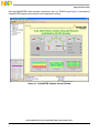
5.5 FreeMASTER Software . . . . . . . . . . . . . . . . . . . . . . . . . . . . . . . . . . . . . . . . . . . . . . . . . . . . . . . 35
Chapter 6
Application Setup
6.1 Application Description . . . . . . . . . . . . . . . . . . . . . . . . . . . . . . . . . . . . . . . . . . . . . . . . . . . . . . . 37
6.1.1 Control Process . . . . . . . . . . . . . . . . . . . . . . . . . . . . . . . . . . . . . . . . . . . . . . . . . . . . . . . . . . 37
6.1.2 Drive Protection . . . . . . . . . . . . . . . . . . . . . . . . . . . . . . . . . . . . . . . . . . . . . . . . . . . . . . . . . . 38
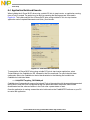
6.2 Application Set-Up . . . . . . . . . . . . . . . . . . . . . . . . . . . . . . . . . . . . . . . . . . . . . . . . . . . . . . . . . . . 40
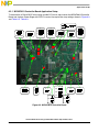
6.2.1 MC56F8013 Controller Board Application Setup . . . . . . . . . . . . . . . . . . . . . . . . . . . . . . . . . 41
6.3 Project Files . . . . . . . . . . . . . . . . . . . . . . . . . . . . . . . . . . . . . . . . . . . . . . . . . . . . . . . . . . . . . . . . 43
6.4 Application Build and Execute . . . . . . . . . . . . . . . . . . . . . . . . . . . . . . . . . . . . . . . . . . . . . . . . . . 44

3-Phase BLDC Drive Using Variable DC Link Six-Step Inverter, Rev. 1
Freescale Semiconductor 7
Chapter 1
Introduction
1.1 Introduction
This paper describes the design of a 3-phase BLDC drive using a variable DC link six-step inverter, based
on Freescale’s MC56F8013 dedicated motor control device.
Recently, small high-speed BLDC motors have become very popular in a wide application area. The
BLDC motor does not have a mechanical commutator and is, consequently, more reliable than the DC
motor. Small high-speed BLDC motors have very low inductance compared to conventional BLDC
motors. When PWM control is applied to the phases of a BLDC motor, the current follows the rectangular
PWM voltage shape. This rapidly changing current magnetizes and demagnetizes the motor iron at a
frequency equal to the PWM frequency. Due to magnetic hysteresis losses, the motor can become hot
enough to be damaged and the high current ripple will cause other losses. Because of the special control
required by the motor, the method adopted in this reference design uses a variable DC link six-step
inverter r to generate the desired voltage for the motor. The motor then requires only a conventional
three-phase inverter for commutation.
The concept of the application is a high-speed BLDC motor with closed-loop speed-control. It serves as
a design example of a 3-phase BLDC drive with variable DC link six-step inverter, using a Freescale
digital signal controller.
This reference design includes basic motor theory, system design concept, hardware implementation,
and the software design, including the FreeMASTER software visualization tool.
1.2 Freescale Controller Advantages and Features
The Freescale MC56F801x family is well suited to digital motor control, combining the DSP’s calculation
capability with the MCU’s controller features on a single chip. These digital signal controllers offer many
dedicated peripherals such as pulse width modulation (PWM) modules, analog-to-digital converters
(ADC), timers, communication peripherals (SCI, SPI, I
2
C), and on-board Flash and RAM.
The MC56F801x family members provide the following peripheral blocks:
• One PWM module (although with a limited pinout on the MC56F8014) with PWM outputs, fault
inputs, fault-tolerant design with dead time insertion, supporting both center-aligned and
edge-aligned modes
• 12-bit ADCs, supporting two simultaneous conversions; ADC and PWM modules can be
synchronized
• One dedicated 16-bit general purpose quad timer module
• One serial peripheral interface (SPI)
• One serial communications interface (SCI) with LIN slave functionality
• One inter-integrated circuit (I
2
C) port
• On-board 3.3V to 2.5V voltage regulator for powering internal logic and memories

Introduction
3-Phase BLDC Drive Using Variable DC Link Six-Step Inverter, Rev. 1
8 Freescale Semiconductor
• Integrated power-on reset and low voltage interrupt module
• All pins multiplexed with general purpose input/output (GPIO) pins
• Computer operating properly (COP) watchdog timer
• External reset input pin for hardware reset
• JTAG/On-Chip Emulation (OnCE™) module for unobtrusive, processor-speed-independent
debugging
• Phase-locked loop (PLL) based frequency synthesizer for the digital signal controller core clock,
with on-chip relaxation oscillator
BLDC motor control benefits greatly from the flexible PWM module, fast ADC, and quad timer module.
The PWM offers flexibility in its configuration, enabling efficient control of the BLDC motor. The PWM
block has the following features:
• Three complementary PWM signal pairs, six independent PWM signals (or a combination)
• Complementary channel operation features
• Independent top and bottom dead time insertion (56F8013)
• Separate top and bottom pulse width correction via current status inputs or software
• Separate top and bottom polarity control
• Edge-aligned or center-aligned PWM reference signals
• 15-bit resolution
• Half-cycle reload capability
• Integral reload rates from one to sixteen periods
• Mask/swap capability
• Individual, software-controlled PWM output
• Programmable fault protection
• Polarity control
• 10mA or 16mA current sink capability on PWM pins
• Write-protectable registers
The PWM module is capable of controlling two PWM signals for the variable DC link six-step inverter. It
can be configured to a switching frequency of 100kHz with a resolution of 1 in 960, i.e. almost 10-bit. The
PWM module generates its reload signal; it can then be used to synchronize other modules to the PWM.
The four remaining PWM channels are used for phase A and phase B of the 3-phase inverter, which takes
care of the motor commutation using the mask feature of the DSC. Phase C is controlled by two GPIO
pins.
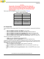
Table 1-1. Memory Configuration
Memory Type MC56F8013 MC56F8014
Program Flash 16 Kbyte 16 Kbyte
Unified Data/Program RAM 4 Kbyte 4 Kbyte

Freescale Controller Advantages and Features
3-Phase BLDC Drive Using Variable DC Link Six-Step Inverter, Rev. 1
Freescale Semiconductor 9
The ADC module has the following features:
• 12-bit resolution
• Dual ADCs per module; three input channels per ADC
• Maximum ADC clock frequency of 5.33MHz with a 187ns period
• Sampling rate of up to 1.78 million samples per second
• Single conversion time of 8.5 ADC clock cycles (8.5 x 187ns = 1.59ms)
• Additional conversion time of six ADC clock cycles (6 x 187ns = 1.125ms)
• Eight conversions in 26.5 ADC clock cycles (26.5 x 187ns = 4.97ms) using parallel mode
• Ability to use the SYNC input signal to synchronize with the PWM (provided the integration allows
the PWM to trigger a timer channel connected to the SYNC input)
• Ability to sequentially scan and store up to eight measurements
• Ability to scan and store up to four measurements on each of two ADCs operating simultaneously
and in parallel
• Ability to scan and store up to four measurements on each of two ADCs operating asynchronously
to each other in parallel
• Interrupt generating capabilities at the end of a scan when out-of-range limit is exceeded and on
zero crossing
• Optional sample correction by subtracting a pre-programmed offset value
• Signed or unsigned result
• Single-ended or differential inputs
• PWM outputs with hysteresis for three of the analog inputs
The ADC is used to measure DC bus voltage, variable DC link six-step inverter output voltage, DC bus
current, and +0.2V voltage and +1.65V current references.
The application uses the ADC block in simultaneous mode scan. It is synchronized to the PWM pulses.
This configuration allows the simultaneous conversion of the required analog values of current and
voltage within the required time.
The quad timer is an extremely flexible module, providing all required services relating to time events. It
has the following features:
• Four 16-bit counters/timers
• Count up/down
• Counters are cascadable
• Programmable count modulus
• Maximum count rate equal to the peripheral clock/2, when counting external events
• Maximum count rate equal to the peripheral clock/1, when using internal clocks
• Count once or repeatedly
• Counters are preloadable
• Counters can share available input pins
• Each counter has a separate prescaler
• Each counter has capture and compare capability

Introduction
3-Phase BLDC Drive Using Variable DC Link Six-Step Inverter, Rev. 1
10 Freescale Semiconductor
The application uses four channels of the quad timer for:
• PWM-to-ADC synchronization
• Hall sensor edge scanning used for speed calculation
• System base for ramp and speed control
• Commutation advance control

3-Phase BLDC Drive Using Variable DC Link Six-Step Inverter, Rev. 1
Freescale Semiconductor 11
Chapter 2
Control Theory
2.1 BLDC Motor
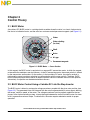
A brushless DC (BLDC) motor is a rotating electric machine where the stator is a classic 3-phase stator,
like that of an induction motor, and the rotor has surface-mounted permanent magnets (see Figure 2-1).
Figure 2-1. BLDC Motor — Cross Section
In this respect, the BLDC motor is equivalent to a reversed DC commutator motor, in which the magnet
rotates while the conductors remain stationary. In the DC commutator motor, the current polarity is altered
by the commutator and brushes. On the contrary, in the brushless DC motor, the polarity reversal is
performed by power transistors switching in synchronization with the rotor position. Therefore, BLDC
motors often incorporate either internal or external position sensors to discern the actual rotor position;
alternatively, the position can be detected without sensors.
2.2 BLDC Motor Control Using a Variable DC Link Six-Step Inverter
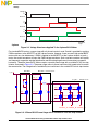
The BLDC motor is driven by rectangular voltage waveforms coupled with the given rotor position (see
Figure 2-2). The generated stator flux interacts with the rotor flux generated by a rotor magnet, defining
the torque, and thus speed, of the motor. The voltage waveforms must be properly applied to the two
phases of the 3-phase winding system, to keep the angle between the stator flux and the rotor flux close
to 90° to generate maximum torque. To achieve this, the motor requires electronic control for proper
operation.
Stator
Stator winding
(in slots)
Shaft
Rotor
Air gap
Permanent magnets

Control Theory
3-Phase BLDC Drive Using Variable DC Link Six-Step Inverter, Rev. 1
12 Freescale Semiconductor
3-phase
Figure 2-2. Voltage Waveforms Applied To the 3-phase BLDC Motor
For standard BLDC motors, a power stage with a 3-phase inverter is used. Control is provided by applying
PWM waveforms to the MOSFETs of the 3-phase inverter. However, there are small high-speed BLDC
motors with very low inductance. If PWM is applied to the MOSFETs of the 3-phase inverter of such a
motor, the current waveform will copy the PWM voltage waveform. Such a current waveform will rapidly
and frequently magnetize and demagnetize the metal causing huge thermal losses due to magnetic
hysteresis. Therefore, these BLDC motors require a special power stage with a variable DC link six-step
inverter, illustrated in Figure 2-3. The power stage uses six power transistors fully turned on/off to control
the commutation. The voltage level is controlled by two transistors in the variable DC link six-step inverter.
Figure 2-3. 3-Phase BLDC Power Stage with a Variable DC Link Six-Step Inverter
30º 60º 90º 120º 150º 180º 210º 240º 270º 300º 330º
Electrical
an
g
le
Voltage
Phase A
Phase B
Phase C
+U
DCB
-U
DCB
+U
DCB
-U
DCB
+U
DCB
-U
DCB
GND_PWR
V_PWR
C
Phase_A Phase_B Phase_C
3-ph. Inverte
r
DC/DC InverterBrake
L
Brake
DCDC_Top
DCDC_Botom
PWM_AT
PWM_AB
PWM_BT
PWM_BB
PWM_CT
PWM_CB

Commutation
3-Phase BLDC Drive Using Variable DC Link Six-Step Inverter, Rev. 1
Freescale Semiconductor 13
The variable DC link six-step inverter controls the voltage on the motor, while commutation is performed
by the 3-phase inverter. The variable DC link six-step inverter output is controlled by switching the
DCDC_Top MOSFET (Figure 2-3). Thus, the variable DC link six-step inverter uses the inductor L and
the capacitor C to keep output voltage at the desired level.
This variable DC link six-step inverter can also work in the opposite direction, i.e. during braking, it can
transfer energy to the power supply’s input voltage level. To reduce the load voltage level during motor
braking, the DCDC_Bottom MOSFET is used. If this MOSFET is turned on, the inductor is charged. In the
instant when the MOSFET is turned off, the energy accumulated in the inductor is transferred to the
variable DC link six-step inverter’s input. This temporarily causes a higher voltage at the input. For longer
operations, the input capacitor will not absorb all the energy, and the input voltage will be higher. In this
case, care must be taken, and the braking MOSFET must be turned on while the voltage is higher, to
reduce the voltage to a safe level.
The bottom MOSFET of the variable DC link six-step inverter operates in a different way to the top one,
i.e. whereas the top MOSFET can be switched from 0 to 100% of the duty cycle, the bottom one cannot.
The bottom MOSFET can only be switched from 0 to a certain percentage, because the inductor is
discharged when the MOSFET is turned off. This maximum duty cycle depends on the voltages at both
the input and the output.
The 3-phase inverter energizes two BLDC motor phases at the same time. The third phase is not powered
(see Figure 2-2). Thus, we have six voltage vectors that may be applied to the BLDC motor.
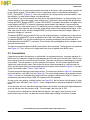
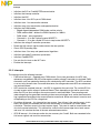
2.3 Commutation
Commutation provides the creation of a rotation field. As explained previously, for proper operation of a
BLDC motor it is necessary to keep the angle between the stator and rotor flux close to 90°. With six-step
control we get a total of six possible stator flux vectors. The stator flux vector must be changed at a certain
rotor position. The rotor position is usually sensed by Hall sensors. The Hall sensors generate three
signals also comprising six states. Each of the Hall sensor states corresponds to a certain stator flux
vector. All Hall sensor states with corresponding stator flux vectors are illustrated in Figure 2-4. The same
figure is illustrated in tables Table 2-1 and Table 2-2.
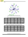
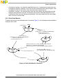
The next two figures depict the commutation process. The actual rotor position in Figure 2-5 corresponds
to the Hall sensors’ state ABC[110] (see Figure 2-4). The actual voltage pattern can be derived from the
Table 2-1. Phase A is connected to the positive DC bus voltage by the transistor PWM_AT, phase C is
connected to ground by transistor PWM_CB, and phase B is not powered.
As soon as the rotor reaches a certain position (see Figure 2-5), the Hall sensor state changes its value
from ABC[110] to ABC[100]. From Table 2-1 a new voltage pattern is selected and applied to the BLDC
motor.
As can be seen, with a six-step control technique there is no possibility of keeping the angle between the
rotor flux and the stator flux precisely at 90°. The real angle varies from 60° to 120°.
The commutation is repeated for each 60 electrical degrees. The angular (time) accuracy of the
commutation event is critical; any deviation causes torque ripples leading to variations in speed.

Control Theory
3-Phase BLDC Drive Using Variable DC Link Six-Step Inverter, Rev. 1
14 Freescale Semiconductor
Figure 2-4. Stator Flux Vectors with Six-Step Control
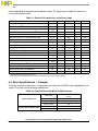
Table 2-1. Commutation Sequence for Clockwise Rotation
Hall Sensor A Hall Sensor B Hall Sensor C Phase A Phase B Phase C
100–V
DCB
+V
DCB
NC
101NC+V
DCB
–V
DCB
001+V
DCB
NC –V
DCB
011+V
DCB
–V
DCB
NC
010NC–V
DCB
+V
DCB
110–V
DCB
NC +V
DCB
Table 2-2. Commutation Sequence for Counterclockwise Rotation
Hall Sensor A Hall Sensor B Hall Sensor C Phase A Phase B Phase C
100+V
DCB
–V
DCB
NC
110+V
DCB
NC –V
DCB
010NC+V
DCB
–V
DCB
011–V
DCB
+V
DCB
NC
001–V
DCB
NC +V
DCB
101NC–V
DCB
+V
DCB

Commutation
3-Phase BLDC Drive Using Variable DC Link Six-Step Inverter, Rev. 1
Freescale Semiconductor 15
Figure 2-5. Situation Right Before Commutation
Figure 2-6. Situation Right After Commutation

Control Theory
3-Phase BLDC Drive Using Variable DC Link Six-Step Inverter, Rev. 1
16 Freescale Semiconductor
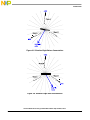
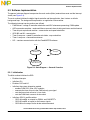
2.4 Speed and Voltage Control
Commutation ensures proper rotor rotation of the BLDC motor, while the motor speed depends only on
the amplitude of the applied voltage. The amplitude of the applied voltage is adjusted by the variable DC
link six-step inverter using pulse width modulation. The required speed is controlled by a speed controller.
The speed and voltage controllers are implemented as conventional PI controllers. The difference
between the actual and required speed (voltage) is the input to the PI controller. Using this difference, the
PI controller controls the duty cycle of PWM pulses fed to the variable DC link six-step inverter,
corresponding to the voltage amplitude required to keep the desired speed. See Figure 2-7.
Figure 2-7. Speed Control
The speed controller calculates output voltage u(t) using a proportional-integral (PI) algorithm, in
accordance with the following equations:
(2-1)
After transformation to a discrete time domain using an integral approximation by a Backward Euler
method, we get the following equations for the numerical PI controller calculation:
(2-2)
(2-3)
(2-4)
where:
e(t) = Input error in time t
u
p
(k)
= Proportional output portion in step k
e(k) = Input error in step k
u
I
(k)
= Integral output portion in step k
w(k) = Desired value in step k
u
I
(k-1)
= Integral output portion in step k-1
m(k) = Measured value in step k
T
I
= Integral time constant
u(t) = Controller output in time t T = Sampling time
u(k) = Controller output in step k
K
c
= Controller gain
Speed
Controller
Vol t age
Cont r ol l er
Σ Σ
DC/ DC
Inverter
3-ph.
Inverter
-
+
PWM
Generator
C o mmu t a t i on
Hall Sensors
M
-
+
Actual Speed
Desi r ed
S
peed
Actual Voltage
Speed
Controller
Vol t age
Cont r ol l er
ΣΣ ΣΣ
DC/ DC
Inverter
3-ph.
Inverter
-
+
PWM
Generator
C o mmu t a t i on
Hall Sensors
M
-
+
Actual Speed
Desi r ed
S
peed
Actual Voltage
ut() K
c
et()
1
T
I
-----
e τ()τd
0
t
∫
+=
uk() u
P
k() u
I
k()+=
u
P
k() K
c
ek()⋅=
u
I
k() u
I
k1–()K
c
+
T
T
I
-----
ek()⋅=

Speed and Voltage Control
3-Phase BLDC Drive Using Variable DC Link Six-Step Inverter, Rev. 1
Freescale Semiconductor 17
The voltage controller calculates the output PWM duty cycle for the variable DC link six-step inverter using
the same proportional-integral (PI) algorithm as the speed controller.

Control Theory
3-Phase BLDC Drive Using Variable DC Link Six-Step Inverter, Rev. 1
18 Freescale Semiconductor

3-Phase BLDC Drive Using Variable DC Link Six-Step Inverter, Rev. 1
Freescale Semiconductor 19
Chapter 3
System Concept
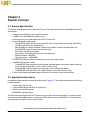
3.1 System Specification
The system is designed to drive a 3-phase BLDC motor. The application meets the following performance
specification:
• Voltage control of BLDC motor using Hall sensors
• Targeted at the MC56F8013 controller board
• Running on 3-Phase Power Stage with DC/DC Inverter Lite
• Control technique incorporating:
– Voltage BLDC motor control using variable DC link six-step inverter with voltage closed loop
– Closed-loop BLDC motor speed control
– Both directions of rotation (however, because an impeller is used in the application, the
FreeMASTER page is locked to one direction only)
– Both motor and generator modes
– Starting from any motor position without rotor alignment
– Minimum speed – 300 RPM
– Maximum speed – 38000 RPM
• FreeMASTER software control interface (motor start/stop, speed setup)
• FreeMASTER software monitor
– FreeMASTER software graphical control page (required speed, actual motor speed, start/stop
status, DC bus voltage level, motor current, system status)
– FreeMASTER software speed scope (observes actual and desired speeds)
– FreeMASTER software Hall sensor scope (observes actual Hall sensors’ state)
• DC bus overvoltage and undervoltage, overcurrent, Hall sensors cable fault protection
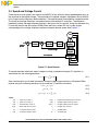
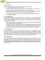
3.2 Application Description
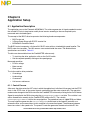
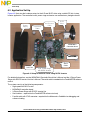
A standard system concept is chosen for the drive (see Figure 3-1). The system incorporates the following
hardware boards:
• Power supply 24V DC, 5A
• 3-Phase Power Stage with DC/DC Inverter Lite
• BLDC motor with Hall sensors
• MC56F8013 controller board
The 3-Phase Power Stage with DC/DC Inverter Lite runs the main control algorithm. In response to the
user interface and feedback signals, it generates PWM signals for the variable DC link six-step inverter
and 3-phase output signals for a 3-phase inverter.

System Concept
3-Phase BLDC Drive Using Variable DC Link Six-Step Inverter, Rev. 1
20 Freescale Semiconductor
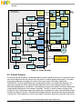
Figure 3-1. System Concept
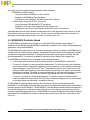
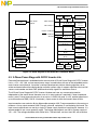
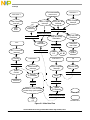
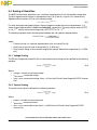
3.3 Control Process
The state of the user interface is scanned periodically, while the speed of the motor is measured on each
new arriving edge from the Hall sensors (only one phase is used for speed measurement). The speed
command is calculated, according to the state of the control signals (Start/Stop, Speed from
FreeMASTER). Then the speed command is processed by means of the speed ramp algorithm. The
comparison between the actual speed command obtained from the ramp algorithm output and the
measured speed generates a speed error. The speed error is input to the speed PI controller, generating
a new desired voltage level for the voltage PI controller. The ADC is used to measure voltage at the
variable DC link six-step inverter output and a digital filter is applied to this value. Then the filtered voltage
is fed to the voltage PI controller. The comparison between the measured and desired voltages generates
a voltage error. The voltage error is input to the voltage PI controller, generating a new duty cycle for the
PW M_0-3
GPIO_A6
GPIO_B3
ADC
QT_0
GPIO_B5
GPIO_B2
Commutation
Handler
GPIO_B1
Speed
Calculation
Speed
PI Controller
100kHz
Voltage
PI Controller
Voltage
level control
Duty cycle
Voltage, current
Desired
voltage
Actual
speed
SCI
Freemaster
Desired
speed
Speed
Ramp
Speed
command
MOSFET
Predriver
GPIO_B0
Application
State Machine
MOSFET
Predriver
Predriver
on/off
Brake
Resistance
DC/DC
Inverter
3-phase
Inverter
M
Hall sensors
15V
5V
3.3V
Power
input
Power
input
PC
FreeMASTER
RS232
MC56F8013
Controller Board
3-ph. Power Stage with
DC/DC Inverter Lite
Power
Supply
Voltage
50kHz
QT_3
PWM Reload
MOSFET
Predriver
QT_2
QT_1
Advance
Interrupt
1kHz
Digital
filtering
Trigger
50kHz
PWM_4
PWM_5
Page is loading ...
Page is loading ...
Page is loading ...
Page is loading ...
Page is loading ...
Page is loading ...
Page is loading ...
Page is loading ...
Page is loading ...
Page is loading ...
Page is loading ...
Page is loading ...
Page is loading ...
Page is loading ...
Page is loading ...
Page is loading ...
Page is loading ...
Page is loading ...
Page is loading ...
Page is loading ...
Page is loading ...
Page is loading ...
Page is loading ...
Page is loading ...
Page is loading ...
Page is loading ...
Page is loading ...
Page is loading ...
Page is loading ...
Page is loading ...
Page is loading ...
Page is loading ...
-
 1
1
-
 2
2
-
 3
3
-
 4
4
-
 5
5
-
 6
6
-
 7
7
-
 8
8
-
 9
9
-
 10
10
-
 11
11
-
 12
12
-
 13
13
-
 14
14
-
 15
15
-
 16
16
-
 17
17
-
 18
18
-
 19
19
-
 20
20
-
 21
21
-
 22
22
-
 23
23
-
 24
24
-
 25
25
-
 26
26
-
 27
27
-
 28
28
-
 29
29
-
 30
30
-
 31
31
-
 32
32
-
 33
33
-
 34
34
-
 35
35
-
 36
36
-
 37
37
-
 38
38
-
 39
39
-
 40
40
-
 41
41
-
 42
42
-
 43
43
-
 44
44
-
 45
45
-
 46
46
-
 47
47
-
 48
48
-
 49
49
-
 50
50
-
 51
51
-
 52
52


Ask a question and I''ll find the answer in the document
Finding information in a document is now easier with AI
Related papers
Other documents
-
Motorola M68HC08 User manual
-
-
-
NXP Semiconductors KEA128LEDLIGHTRD Installation Instructions Manual
-
Cypress Semiconductor CY8CKIT-037 User manual
-
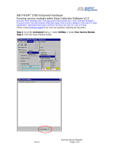 Thermo Fisher Scientific ABI PRISM® 3700 User guide
-
Silicon Laboratories SENSORLESS-BLDC-MOTOR-RD User manual
-
Freescale Semiconductor RS08 User manual
-
-
Microchip Technology MCP8063 User manual
