Page is loading ...

DC to DC Motor Control
Instruction Manual
Software Number: 44300
Part Number: 144-47014 R0
September 2018
© Copyright 2018 Magnetek

OmniPulse DDC Series 2 Instruction Manual
September 2018
Page i
Page Intentionally Left Blank

OmniPulse DDC Series 2 Instruction Manual
September 2018
Page ii
Table of Contents
Chapter 1 Introduction ............................................................................................................................1-1
1 General Information ...........................................................................................................................1-3
1.1 Key Features .............................................................................................................................1-3
1.2 Receiving Check List.................................................................................................................1-4
1.3 Assessing the System Requirements........................................................................................1-4
1.4 Assessing the Drive Environment .............................................................................................1-4
1.5 OmniPulse DDC Series 2 General Specifications .....................................................................1-5
Chapter 2 Installation ..............................................................................................................................2-1
2 Choosing a Location ..........................................................................................................................2-2
2.1 Standard OmniPulse DDC Series 2 Drive Components ...........................................................2-3
2.1.1 Optional Drive Components..................................................................................................2-6
2.1.2 As-Required External Components ......................................................................................2-6
2.1.3 Required External Devices ...................................................................................................2-6
2.1.4 Series Mill Motor Ratings ......................................................................................................2-7
2.1.5 DB Resistor Sizing General Formula..................................................................................2-10
2.2 Storage....................................................................................................................................2-10
2.2.1 Long-Term Storage.............................................................................................................2-10
2.2.2 Bus Capacitor Reforming Procedure ..................................................................................2-10
2.3 Installing the Drive...................................................................................................................2-12
2.4 Drive Derating Data.................................................................................................................2-12
2.4.1 Temperature Derating.........................................................................................................2-12
2.4.2 Altitude Derating .................................................................................................................2-12
2.5 Chassis Dimensions and Weight.............................................................................................2-12
2.6 Heat and Watt Loss.................................................................................................................2-14
Chapter 3 Wiring......................................................................................................................................3-1
3 Power Circuit Wiring ..........................................................................................................................3-2
3.1 Hoist Mode ................................................................................................................................3-2
3.2 Traverse Mode ..........................................................................................................................3-3
3.3 Power Circuit Wiring Procedures ..............................................................................................3-4
3.3.1 Grounding .............................................................................................................................3-4
3.4 Control Board ............................................................................................................................3-7
3.4.1 Control Board Jumper Settings.............................................................................................3-7
3.4.2 Control Circuit Terminals ......................................................................................................3-8
3.5 Gate Driver Board ...................................................................................................................3-10
3.6 Interface Board (230 VDC)......................................................................................................3-13
3.7 External CT Board / Shunt Board............................................................................................3-14
Chapter 4 Getting Started .......................................................................................................................4-1
4 Overview............................................................................................................................................4-2
4.1 Checks Before Powering...........................................................................................................4-2
4.2 Precautions ...............................................................................................................................4-2
4.3 Using the DLS4 Keypad ............................................................................................................4-2
4.3.1 Keypad LED and Button Functions.......................................................................................4-3
4.4 Parameters................................................................................................................................4-4
4.4.1 DLS4 Keypad Menu Structure ..............................................................................................4-5
4.4.2 Initialization Setup.................................................................................................................4-7
Chapter 5 Programming Advanced Features .......................................................................................5-1
5 Introduction ........................................................................................................................................5-2
5.1 Application.................................................................................................................................5-2
5.1.1 Preset Reference..................................................................................................................5-2
5.2 Special Functions ......................................................................................................................5-7

OmniPulse DDC Series 2 Instruction Manual
September 2018
Page iii
5.2.1 Micro-Speed (C02-01 and C02-02) ......................................................................................5-7
5.2.2 Travel Limits .........................................................................................................................5-8
5.2.3 Current Limits (C07-01 and C07-02) ..................................................................................5-12
5.2.4 Brake Control (C08-04 through C08-21).............................................................................5-12
5.2.5 Rescue Mode (C08-25) ......................................................................................................5-14
5.2.6 Slack Cable Detection (C11-01 through C11-04) ...............................................................5-14
5.2.7 Timer Function (C12-03 and C12-04) .................................................................................5-15
5.3 Drive Settings ..........................................................................................................................5-16
5.3.1 Start and Stop Functions (D01-01 through D01-05) ...........................................................5-16
5.3.2 Automatic Speed Regulator (D04-01 through D04-10).......................................................5-18
5.3.3 Torque Follower (D05-01)...................................................................................................5-19
5.4 Motor Setup.............................................................................................................................5-21
5.4.1 Field Settings (E01-01 through E01-08) .............................................................................5-21
5.4.2 Motor Settings.....................................................................................................................5-25
5.5 Motor Feedback ......................................................................................................................5-27
5.5.1 Tachometer Feedback (F02-01 through F02-05) ...............................................................5-27
5.6 Terminal Parameters...............................................................................................................5-28
5.6.1 Digital Inputs (H01-01 through H01-12) ..............................................................................5-28
5.6.2 Digital Outputs (H02-01 through H02-07) ...........................................................................5-31
5.6.3 Analog Inputs (H03-01 through H03-08).............................................................................5-32
5.6.4 Analog Outputs (H04-01 through H04-07) ..........................................................................5-33
5.6.5 Serial Communications (H05-01 through H05-09)..............................................................5-35
5.7 Protection ................................................................................................................................5-36
5.7.1 DC Bus Levels (L02-01 and L02-02) ..................................................................................5-37
5.7.2 Motor Protection (L08-01 through L08-09) .........................................................................5-38
5.7.3 Fault Reset (L09-01 and L09-02)........................................................................................5-39
5.8 Operator ..................................................................................................................................5-41
5.8.1 Drive Configuration .............................................................................................................5-41
5.8.2 Maintenance (O03-01 through O03-11)..............................................................................5-44
Chapter 6 Troubleshooting.....................................................................................................................6-1
6 Troubleshooting .................................................................................................................................6-2
6.1 Monitor Parameters...................................................................................................................6-2
6.2 Maintenance and Inspection .....................................................................................................6-8
6.2.1 Replacing the Keypad Battery ..............................................................................................6-9
6.3 Fault Codes and Corrective Action..........................................................................................6-10
6.4 Short-Circuit Check .................................................................................................................6-17
Appendix A - Modbus RTU Communications ...................................................................................... A-1
Appendix B - Parameter Listing ............................................................................................................ B-1
Appendix B - DDC Series 1 to DDC Series 2 Parameter Reference................................................... C-1

OmniPulse DDC Series 2 Instruction Manual
September 2018
Page iv
SERVICE INFORMATION
U.S. Service Information:
For questions regarding service or technical information contact:
1-866-MAG-SERV
(1-866-624-7378)
International Service
262-783-3500
World Headquarters:
Magnetek, Material Handling
N49 W13650 Campbell Drive
Menomonee Falls, WI 53051
Telephone: 800-288-8178
Website: www.magnetek.com
E-mail: mhcustomerse[email protected]
Fax Numbers:
Main: 800-298-3503
Sales: 262-783-3510
Service: 262-783-3508
© 2018 MAGNETEK
All rights reserved. This notice applies to all copyrighted materials included with this product, including, but
not limited to, this manual and software embodied within the product. This manual is intended for the sole
use of the person(s) to whom it was provided, and any unauthorized distribution of the manual or dispersal
of its contents is strictly forbidden. This manual may not be reproduced in whole or in part by any means
whatsoever without the expressed written permission of MAGNETEK.
Parts of this product may be covered by patent US006710574B2.
Canada Service Information:
161 Orenda Road
Unit 1
Brampton, Ontario
L6W 1W3 Canada
Phone: 800-792-7253
Fax: 905-828-5707
EU Market Contact:
Brian Preston
Magnetek (UK) Ltd.
Unit 3 Bedford Business Centre
Mile Road
Bedford, MK42 9TW UK
Phone: +44-1234-349191
Fax: +44-1234-268955

OmniPulse DDC Series 2 Instruction Manual
September 2018
Page v
PREFACE AND SAFETY
Magnetek, Inc. (Magnetek) offers a broad range of radio remote control products, control products,
adjustable frequency drives, and industrial braking systems for material handling applications. This manual
has been prepared by Magnetek to provide information and recommendations for the installation, use,
operation and service of Magnetek’s material handling products and systems (Magnetek Products).
Anyone who uses, operates, maintains, services, installs or owns Magnetek Products should know,
understand and follow the instructions and safety recommendations in this manual for Magnetek Products.
The recommendations in this manual do not take precedence over any of the following requirements
related to cranes, hoists, lifting devices or other material handling equipment which use or include
Magnetek Products:
• Instructions, manuals, and safety warnings of the manufacturers of the equipment where the
Magnetek Products are used,
• Plant safety rules and procedures of the employers and the owners of the facilities where the
Magnetek Products are being used,
• Regulations issued by the Occupational Health and Safety Administration (OSHA),
• Applicable local, state or federal codes, ordinances, standards and requirements, or
• Safety standards and practices for the industries in which Magnetek Products are used.
This manual does not include or address the specific instructions and safety warnings of these
manufacturers or any of the other requirements listed above. It is the responsibility of the owners, users
and operators of the Magnetek Products to know, understand and follow all of these requirements. It is the
responsibility of the employer to make its employees aware of all of the above listed requirements and to
make certain that all operators are properly trained. No one should use Magnetek Products prior to
becoming familiar with and being trained in these requirements and the instructions and safety
recommendations for this manual.
Product Warranty Information
Magnetek, hereafter referred to as Company, assumes no responsibility for improper programming of a
drive by untrained personnel. A drive should only be programmed by a trained technician who has read
and understands the contents of this manual. Improper programming of a drive can lead to unexpected,
undesirable, or unsafe operation or performance of the drive. This may result in damage to equipment or
personal injury. Company shall not be liable for economic loss, property damage, or other consequential
damages or physical injury sustained by the purchaser or by any third party as a result of such
programming. Company neither assumes nor authorizes any other person to assume for Company any
other liability in connection with the sale or use of this product.
WARRANTY INFORMATION
FOR INFORMATION ON MAGNETEK’S PRODUCT WARRANTIES BY PRODUCT TYPE, PLEASE
VISIT WWW.MAGNETEK.COM.
WARNING
Improper programming of a drive can lead to unexpected, undesirable, or unsafe operation or
performance of the drive.

OmniPulse DDC Series 2 Instruction Manual
September 2018
Page vi
DANGER, WARNING, CAUTION and NOTE Statements
Read and understand this manual before installing, operating or servicing this product. Install the product
according to this manual and local codes.
The following conventions indicate safety messages in this manual. Failure to heed these messages could
cause fatal injury or damage products and related equipment and systems.
DANGERS, WARNINGS and CAUTIONS
Throughout this document DANGERS, WARNING and CAUTION statements have been deliberately
placed to highlight items critical to the protection of personnel and equipment.
NOTE: A NOTE statement is used to notify people of installation, operation, programming or maintenance
information that is important, but not hazard-related.
DANGERS, WARNINGS and CAUTIONS SHOULD NEVER BE DISREGARDED.
Registered Trademarks
Trademarks are the property of their respective owners.
DANGER
DANGER indicates an imminently hazardous situation which, if not avoided, will result in death or
serious injury. This signal word is to be limited to the most extreme situations.
WARNING
WARNING indicates a potentially hazardous situation which, if not avoided, could result in death or
serious injury.
CAUTION
CAUTION indicates a potentially hazardous situation which, if not avoided, could result in minor or
moderate injury. It may also be used to alert against unsafe practices.

OmniPulse DDC Series 2 Instruction Manual
September 2018
Page 1-1
1
Introduction
C h a p t e r

OmniPulse DDC Series 2 Instruction Manual
September 2018
Page 1-2
This manual provides technical information on OmniPulse DDC Series 2 parameter settings, drive
functions, troubleshooting, and installation details. Use this manual to expand drive functionality and to
take advantage of higher performance features. This manual is available for download on the Magnetek
Material Handling document center website at www.magnetekmh.com.
WARNING
Do not touch any circuitry components while the main power is on.
Do not check signals during operation.
Do not connect the main output terminals (T1, T2, T3, T4) to the incoming DC source.
Read and understand this manual before installing, operating, or servicing this drive. All warnings,
cautions, and instructions must be followed. All activity must be performed by qualified personnel. The
drive must be installed according to this manual and local codes.
Do not connect or disconnect wiring while the power is on. Do not remove covers or touch circuit
boards while the power is on. Do not remove or insert the digital operator while power is on.
Before servicing, disconnect all power to the equipment. The internal capacitor bank remains charged
even after the power supply is turned off. The charge indicator LED will extinguish when the DC bus
voltage is below 50 VDC. To prevent electric shock, wait at least five minutes after all indicators are
OFF and measure DC bus voltage to confirm safe level.
Do not perform a withstand voltage or megger test on any part of the unit. This equipment uses
sensitive devices and may be damaged by high voltage.
Install adequate branch circuit protection per applicable codes. Failure to do so may result in
equipment damage and/or personal injury.
Do not connect unapproved LC or RC interference suppression filters, capacitors, or overvoltage
protection devices to the output of the drive. These devices may generate peak currents that exceed
drive specifications.

OmniPulse DDC Series 2 Instruction Manual
September 2018
Page 1-3
1 General Information
Magnetek’s OmniPulse DDC Series 2 provides stepped or stepless control of DC series, shunt, and
compound motors used for hoist, bridge, and trolley crane motions. A static regulating system
automatically provides torque and speed regulation in all four motor quadrants.
1.1 Key Features
• 5 to 500 horsepower range
• Four-quadrant operation for motoring and regenerative operations in both directions
• Adjustable and repeatable speed and torque control
• X-Press programming for short setup times
• Micro-Speed™ control for precise positioning
• Modular construction, with easy access to drive components
• Numerous safety circuits for maximum protection of personnel and components
• Programmable smooth acceleration and deceleration for repeatable speed control
• DLS4 display keypad for user-friendly monitoring, data logging, and troubleshooting
• Solid-state design that eliminates wearing parts and reduces maintenance downtime
• Elimination of the need for resistors and contactors, reducing space and weight requirements and
boosting system efficiency
Table 1-1: Typical Equipment List
Quantity Item Description
1
Crane controller in NEMA Type 1 enclosure (standard) or optional NEMA Type 1
gasketed, NEMA Type 3, NEMA Type 4 or NEMA Type 12 enclosure, or open panel
1 Optional Type “F” master switch (and/or other optional operator controls)
1 or 2 Optional holding brake(s)
1 Optional power limit switch and resistor
1 or more Optional over-travel control limit switch(es)
1 Optional DB power loss resistor

OmniPulse DDC Series 2 Instruction Manual
September 2018
Page 1-4
1.2 Receiving Check List
Upon receipt, check each item against the packing slip to ensure item is the same as ordered.
If shipping damage is noted, contact and file a claim with the carrier immediately.
If there is a discrepancy between the packing slip, purchase order and received items, contact Magnetek to
resolve.
1.3 Assessing the System Requirements
It is important to know how the drive will be utilized before working on installation and wiring. Please know
the requirements for the following components:
• Speed control method(s) - i.e., stepped, analog, serial communications
• Power source rating and motor ratings
• Power source location
•Wire size
• Grounding location and method
• Control wiring sources - i.e., cab, pendant, radio
1.4 Assessing the Drive Environment
When choosing a location for OmniPulse DDC Series 2, perform the following steps:
1. Ensure that the drive-to-motor wiring distance is less than 150 ft unless appropriate reactors, filters,
and/or inverter duty motor is used.
2. Ensure that the drive circuit wiring is protected or isolated from:
• Ambient temperatures outside the range of +14°F to +149°F (-10°C to +65°C)
• Rain or moisture
• Corrosive gases or liquids
• Metal chips
• Direct sunlight
• Severe mechanical vibration
3. Ensure that the drive is housed in an appropriate NEMA-rated enclosure. To maintain UL approval, the
drive must be housed in an enclosure requiring a tool to open/access.
WARNING
Maximum motor speed should never be set to exceed the motor’s and driven machine’s capability.

OmniPulse DDC Series 2 Instruction Manual
September 2018
Page 1-5
1.5 OmniPulse DDC Series 2 General Specifications
Table 1-2: Voltage Ratings
* NEMA 5 (400 A) drive is used as the master drive with up to four follower drives (LN5400F-DDC-S2 or
HN5400F-DDC-S2).
Table 1-3: Electrical Ratings
200 – 320 Volts 360 – 600 Volts
Model Number Max. FLA (A) NEMA Rating Model Number Max. FLA (A) NEMA Rating
LN2067-DDC-S2 67 2 HN2067-DDC-S2 67 2
LN3133-DDC-S2 133 3 HN3133-DDC-S2 133 3
LN4200-DDC-S2 200 4 HN4200-DDC-S2 200 4
LN5400-DDC-S2 400* 5 HN5400-DDC-S2 400* 5
LN5400F-DDC-S2 400 6~8L HN5400F-DDC-S2 400 6~8L
Description Specification
Power
Current Range
67 amps to 2000 amps continuous (can control motors as low as
2.5A with External CT Board)
1 Minute Overload Capability
3 Second Overload Capability
150% continuous rating heatsink temperature < 110°C
200% continuous rating heatsink temperature < 85°C
Supply Bus Voltage
+10% to -20%
200 to 320 VDC (Low Voltage models)
360 to 600 VDC (High Voltage models)
Grounding Configurations Full Floating, Grounded Positive, or Grounded Negative
DV/DT Rise 1500 volts per microsecond maximum
Switching Frequency 1 kHz
Control I/O
Digital Inputs
DDC-S2-CONTROL 12 inputs (24 VDC)
DDC-S2-230VIF 9 inputs* (200-300 VDC)
Digital Outputs
DDC-S2-CONTROL 4 relay outputs (up to 120 VAC or 30 VDC, 5A)
DDC-S2-230VIF 3 programmable (230 VDC, 1A)
Analog Inputs DDC-S2-CONTROL 2 inputs (0-10 VDC or 4-20 mA, 250Ω)
Analog Outputs DDC-S2-CONTROL 2 outputs (0-10 VDC, -10 to +10 VDC or 4-20 mA, 250Ω)
Communication
RS-232 Onboard Display, Door Mount Display, or PC Channel
RS-485 PC Channel or PLC Channel
Protective Functions
Power Loss One second Ride-Through capability
Undervoltage
Trip @ less than 50% V
IN
when greater than one second (default)
* Inputs shared with DDC-S2-CONTROL

OmniPulse DDC Series 2 Instruction Manual
September 2018
Page 1-6
Table 1-4: Environmental Specifications
Drive Armature Short Circuit
Current Control Overload Trip
IGBT Individual Overload Trip
IGBT Overcurrent Safe Failure Mode
Drive Thermal
Heat Sink Overtemperature Alarm and Shutdown
Ambient Overtemperature Shutdown
Motor Overload Trip when armature current is greater than 110%
Motor Continuity
Motor connections are verified at the start of each cycle before
the brake is released in hoist mode only.
Emergency Power Loss Dynamic Braking
Standard on Hoist application
Optional on Traverse application
Fuse Protection
DC BUS Power Fuse
Interface Board Fused
Charge Indicator
Visual indicator on drive unit indicating charge state on the
capacitor bank. Backlight display indicates control voltage
presence.
Motor Ground Detection
On hoist applications, both motor armature and series field
detected. On travel applications, motor armature detected. Trip
level is hardware set and is non-adjustable.
Description Specification
Temperature
Ambient Operating Temperature -10°C (no frost) to +65°C
Storage Temperature -40°C to +65°C
Relative Humidity < 90% No Condensation
Altitude
Altitude 3300 Feet (1000 meters), 3000 meters max. with derate
Deration
Temperature 2% per °C above 50°C
Altitude 1% for each 100 meters above 1000
EMC
Immunity and Emissions Complies with EN50081-2
Vibration/Shock
Vibration Complies with EN 60068-2-64
Shock Complies with EN 60068-2-27
Description Specification

OmniPulse DDC Series 2 Instruction Manual
September 2018
Page 2-1
2
Installation
C h a p t e r

OmniPulse DDC Series 2 Instruction Manual
September 2018
Page 2-2
This chapter explains the following:
• Choosing a location
• OmniPulse DDC Series 2 components and external devices
• Drive environment
• Drive installation
In addition, this section will cover information on the components that interconnect with OmniPulse DDC
Series 2.
2 Choosing a Location
Be sure that the drive is mounted in a location protected against the following conditions:
• Extreme cold and heat. Use only within the ambient temperature range:
-10°C to +65°C (+14°F to 149°F)
• Direct sunlight (not for use outdoors)
• Rain, moisture
• High humidity
• Oil sprays, splashes
• Salt spray
• Dust or metallic particles in the air
• Corrosive gases (e.g., sulfurized gas or liquids)
• Radioactive substances
• Combustibles (e.g., thinner, solvents, etc.)
• Physical shock, vibration
• Magnetic noise (e.g., welding machines, power devices, etc.)
WARNING
• When preparing to mount the OmniPulse DDC Series 2 drive, lift it by its base. Never lift the drive
by the front cover, as doing so may cause drive damage or personal injury.
• Mount the drive on nonflammable material.
• The OmniPulse DDC Series 2 drive generates heat. For the most effective cooling possible, mount
it vertically. For more details, refer to the heat loss data in Table 2-5 on page 2-14.
• When mounting units in an enclosure, install a fan or other cooling device to keep the enclosure
temperature below 65°C (149°F).
Failure to observe these warnings may result in equipment damage.

OmniPulse DDC Series 2 Instruction Manual
September 2018
Page 2-3
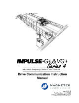
2.1 Standard OmniPulse DDC Series 2 Drive Components
Figure 2-1: Small Chassis – NEMA 2 & 3 Drive
Item No. Part Number Description Qty
1 144-45266 Fan, 24VDC, 4 in., 95 CFM 1
2 144-45065 Fuse, 150A, 500V, 2.75 in. 1
3 144-47016 Control Board 1
4 144-47017 Gate Driver Board, NEMA 2 & 3 1
5 144-27084 DLS4 Assembly 1
2
1
3

OmniPulse DDC Series 2 Instruction Manual
September 2018
Page 2-4
Figure 2-2: Large Chassis – NEMA 4 & 5 Drive
Item No. Part Number Description Qty
1 144-45090 Fan, 24VDC, 6.75 in., 290 CFM 1
2 144-45066 Fuse, 500A, 500V, 3.25 in. 1
3 144-47016 Control Board 1
4 144-47018 Gate Driver Board, NEMA 4 & 5 1
5 144-45064 Bus Discharge Board, NEMA 4 & 5 1
6 144-27084 DLS4 Assembly 1
2
1
5
3

OmniPulse DDC Series 2 Instruction Manual
September 2018
Page 2-5
Figure 2-3: Large Chassis – High-Voltage Drive
Item No. Part Number Description Qty
1 144-27084 DLS4 Assembly 1
2 144-45462 DDC-S2, SZ 4/5 HV, Fuse Bar 1
3 144-45090 Fan, 24VDC, 6.75 in. 1
4 144-47016 Control Board 1
5 144-47019 Gate Driver Board, NEMA 4 & 5 HV 1
6 144-47020 HV Isolation Board 1
1
2
3
5

OmniPulse DDC Series 2 Instruction Manual
September 2018
Page 2-6
2.1.1 Optional Drive Components
• DDC-230VIF External Interface Board
• DDC-EXT-CT External CT Board(s)
2.1.2 As-Required External Components
• Power Limit Switch and Resistor
• Holding Brake(s)
• External dynamic braking power loss resistor(s)
•RPM module
• Overtravel limit switches
• Collision avoidance sensor(s)
2.1.3 Required External Devices
• DC Motor
• User input device (pendant, joystick, PC, PLC, radio, or infrared control)
• External circuit protection devices (fuses or circuit breakers)
• Adequate surge suppressors on contactor coils

OmniPulse DDC Series 2 Instruction Manual
September 2018
Page 2-7
2.1.4 Series Mill Motor Ratings
Table 2-1: 600 Series Mill Motor Ratings
* Estimates only
NOTE: For 300 VDC estimates, multiply 230 VDC hp and RPM ratings by 1.3.
Duty Frame
230 VDC 360 VDC*
Rated Amps
HP RPM HP RPM
1/2 Hour
Rating (Hoist)
602 10 675 16 1060 44
603 13-1/2 620 21 973 57
604 19 560 30 879 77
606 33 515 52 809 129
608 45 470 71 738 175
610 65 445 102 699 248
612 100 430 157 675 375
614 135 400 212 628 500
616 200 400 314 628 730
618 265 385 416 604 955
620 360 340 565 534 1296
622 500 310 785 487 1800
624 660 300 1036 471 2376
1 Hour Rating
(Traverse)
602 7-1/2 800 12 1256 31
603 10 725 16 1138 41
604 15 650 24 1021 59
606 25 575 39 903 95
608 35 525 55 824 131
610 50 500 78 785 184
612 75 475 118 746 274
614 100 460 157 722 360
616 150 450 236 706 536
618 200 410 314 644 712
620 275 370 432 581 1017
622 375 340 589 534 1350
624 500 320 785 502 1800
/