
Software Version 1.31.1
Clinton reserves the right, without notification, to make changes in product design & specification.
Connect PVM
User Manual
For models with Built-in
IP or EX-SDI cameras

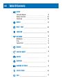
Table Of Contents
ABOUT
REBOOT
DATE / TIME
FACTORY RESET
LOCATION
UPDATE
SUPPORT
CAMERA SETTINGS
LED SETTINGS
EXIT
NETWORK
Wifi Network
Proxy
Captive Portal
SETUP
Connection Diagram
Remote Control Info
Initial Setup
07
16
08
16
09
17
18
19
20
21
10
11
12
14
01
03
04

1
Based on Software Version 1.31.1. Content subject to change without notice. Check www.clintonelectronics.com for the most current manual.
DC24V
3. ALARM OUT
4. GND
1. ALARM1
3. ALARM OUT
4. GND
2. GND
NETWORK
IP
CAMERA
ON
OFF
To NVR
External
Power
Supply
To DHCP
Network
Connection
NETWORK
VIDEO RECORDER
PoE
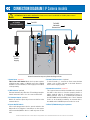
CONNECTION DIAGRAM / IP Camera models
4
3
5
6
7
1. Power Input *required
This is not a PoE device! Main device power requires
a DC24V power supply or 110VAC connection (110VAC
available on select models). Power supply not included,
sold separately.
2. Wifi Antenna *optional
External antenna only oered on 32” and larger models.
Attach antenna if device is to be connected via Wifi.
3. IP Camera Output *optional
Built-in IP camera output only. Connect to NVR or other
network device.
4. Power On/O Switch
After connecting power to device, put the switch to the
ON position. Pressing the Power button on the remote
will not turn On/O the device, it will only turn o the
LCD.
5. Alarm I/O Connections *optional
If desired, make +/- connections from external alarm
output, such as EAS pedestal, to desired Alarm In.
Connections vary by model.
6. Network Connection *required
This connection must either be hardwired or connected
via Wifi for the device to function properly. Cat5e or
higher network cable is recommended. Connect to
DHCP network. There is no communication between
the NETWORK and IP CAMERA ports. If the IP Camera
feed is to be viewed/recorded by an external device,
the additional IP CAMERA port must also be used.
7. VESA 75/100 Mounting hole patterns
1
2
*Actual connections may vary from the image shown.
ATTENTION: This is NOT a PoE Device! Power must come from DC24V or 110VAC power source!

2
Based on Software Version 1.31.1. Content subject to change without notice. Check www.clintonelectronics.com for the most current manual.
ON
OFF
DC24V
3. ALARM OUT
4. GND
1. ALARM1
2. GND
NETWORK
ANALOG
OUTPUT
EX-SDI
OUTPUT
External
Power
Supply
To DVR
EX-SDI / HD-SDI
DVR
PoE
To DHCP
Network
Connection
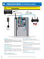
CONNECTION DIAGRAM / EX-SDI Camera models
5
4
3
6
7
8
1
2
*Actual connections may vary from the image shown.
1. Power Input *required
This is not a PoE device! Main device power requires
a DC24V power supply or 110VAC connection (110VAC
available on select models). Power supply not included,
sold separately.
2. Wifi Antenna *optional
External antenna only oered on 32” and larger models.
Attach antenna if device is to be connected via Wifi.
3. Power On/O Switch
After connecting power to device, put the switch to the
ON position. Pressing the Power button on the remote
will not turn On/O the device, it will only turn o the
LCD.
4. Analog Video Output *optional
Connect to Analog DVR or other device.
5. EX-SDI / HD-SDI Video Output *optional
Connect to EX-SDI or HD-SDI compatible DVR or other
device.
6. Alarm I/O Connections *optional
If desired, make +/- connections from external alarm
output, such as EAS pedestal, to desired Alarm In.
Connections vary by model.
7. Network Connection *required
This connection must either be hardwired or connected
via Wifi for the device to function properly. Cat5e or
higher network cable is recommended. Connect to
DHCP network.
8. VESA 75/100 Mounting hole patterns
ATTENTION: This is NOT a PoE Device! Power must come from DC24V or 110VAC power source!

3
Based on Software Version 1.31.1. Content subject to change without notice. Check www.clintonelectronics.com for the most current manual.
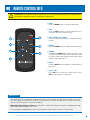
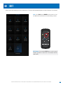
REMOTE CONTROL INFO
1. MENU
Press the MENU button to open the Main Menu.
2. EXIT
Press the EXIT button to close the Main Menu or to
go back to the previous menu screen.
3. LEFT / RIGHT / UP / DOWN
Use these directional buttons to navigate the menu
options.
4. ENTER
Press the ENTER button to confirm a menu selection.
5. POWER
Pressing the POWER button will turn o the LCD.
This does not power o the device. While the screen
is o the camera will still have power and output
video to connected devices.
6. MUTE
Press the MUTE button to disable or enable audio on
this device.
7. VOL + / VOL -
Press VOL + to increase the volume level or press
VOL - to decrease the volume level.
3
4
1
2
ATTENTION: The included remote is required to access the Main Menu and make any adjustments to
menu options. Keep the remote in a safe place for future use.
5
6
7
• If the Remote is lost or misplaced a USB mouse can be used to navigate the Main Menu. Plug the mouse into
one of the USB ports on the rear of the device. Move the mouse cursor to the top left corner of the screen, then
click the left mouse button to open the Main Menu.
• When Advertising Content is shown: Pressing LEFT or RIGHT will navigate forwards or backwards through
advertising content playing on the screen.
• Press and hold the POWER button, then select Restart from the menu if the device is unresponsive.
HELPFUL TIPS:

4
Based on Software Version 1.31.1. Content subject to change without notice. Check www.clintonelectronics.com for the most current manual.
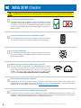
INITIAL SETUP / Checklist
ATTENTION: Verify that the following information is completed before proceeding with the installation.
Do you have the Store Number and Device Group information?
If previously set up by the Clinton Connect admin, there may be additional information that is relevant to your
installation. This information includes the Store Number and/or Device Group. This information is not technically
required to complete the installation and can be changed at a later date.
Is the Connect PVM installed vertically?
Verify the Connect PVM is installed correctly. It should have a vertical
orientation (portrait mode) with the camera located at the bottom
of the device. If the device is installed horizontally both the camera
feed on connected DVR/NVR and the digital signage content will not
display correctly.
Will this be a wired or wireless internet (Wifi) connection?
The Connect PVM is a networked device that requires internet access
to function correctly. If this device can not access the internet, it can
not be completely setup and will not be able to receive advertising
updates. This device will accept either a wired or Wifi internet
connection. For best results a wired connection is recommended.
Do you have the Remote that was included with the PVM?
The included remote is required to complete the initial set up. Keep
the remote in a safe place to make any adjustments at a later date.
Do you have the QR Code?
The company specific QR Code is required to register the device to
the correct company. If the QR Code was not provided contact your
Clinton Connect admin.
Has the network been properly configured?
Depending on the level of network security, some URLs may need to be white-listed on the network. If the
required URLs are not added, the initial set up will fail. For a list of the required URLs consult the Networking
Requirements document which can be found on www.clintonconnect.com/support

5
Based on Software Version 1.31.1. Content subject to change without notice. Check www.clintonelectronics.com for the most current manual.
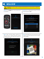
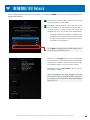
Step 1. Press the ENTER button on the included remote
to get started.
Step 3. After successful network connection, the
device will test it’s Internet Connection and ping
the Clinton Connect Server. Both tests must pass to
proceed with the setup.
INITIAL SETUP
Step 2. Choose a Wifi Network from the list, enter the
password, and select Join.
Step 4. Hold the QR code in front of the Connect PVM
camera to scan. If the code does not scan, you can also
enter it manually.
*Hardwired devices will automatically skip this step
ATTENTION: This device requires a network connection with access to the internet to complete the
initial setup.

6
Based on Software Version 1.31.1. Content subject to change without notice. Check www.clintonelectronics.com for the most current manual.
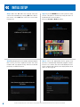
INITIAL SETUP
Step 7. Begin typing the store number when prompted,
then choose your store number from the list. Store
numbers will only appear if they have been entered
previously on Clinton Connect.
Step 8. Select the appropriate device group from
the list to automatically download assigned content.
If there is no content, the device will display the full-
screen camera view until the next deployment to that
device or device group.
Step 6. Press the ENTER button on the remote to Snap
a Photo. This photo is used to help verify the device is
installed in the correct location.
Choose to Accept or Redo the photo.
Step 5. Once the QR Code has scanned, verify the
correct time and date by selecting YES. If the time is
not correct, select NO, then select the correct time
from the list.

7
Based on Software Version 1.31.1. Content subject to change without notice. Check www.clintonelectronics.com for the most current manual.
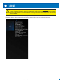
Press the MENU button on the remote to display the Main Menu, then select About. The About screen has basic
information about the device that may be useful during setup or in the event you need technical support.
13” Test Connect PVM
Welcome Ads
Ads 10.1.2019 13.29
Clinton Electronics
C6701E
Main Entrance
CE-P13-B
ABOUT
ATTENTION: Models with built-in IP cameras— IP Camera information WILL NOT be shown on this
screen. IP Camera information can only be viewed after making a connection to the IP Camera (output)
located on the back of the Connect PVM, then accessing camera via internet browser or other network
device/software.

8
Based on Software Version 1.31.1. Content subject to change without notice. Check www.clintonelectronics.com for the most current manual.
DATE/TIME
It is important that the date and time information is set correctly during installation. If the date and time are not correctly
set, scheduled content will not display at the appropriate time.
Set Time Zone. If the Date & Time information is
incorrect, select this to pick a new Time Zone from a
list.
Use the UP or DOWN arrows on the remote to scroll
through the list. Press the ENTER button to select the
correct Time Zone.
Press the EXIT button to leave this screen.

9
Based on Software Version 1.31.1. Content subject to change without notice. Check www.clintonelectronics.com for the most current manual.
While the Store Number and Device Groups are not required, they are helpful when managing large groups of devices
using the Clinton Connect software. Use this menu to edit Store Numbers and Device Group locations.
LOCATION
C6701E
Main Entrance
C6701E
Main Entrance
Change Store. If the Store Number shown in the status
area of the screen is incorrect, select Change Store
and select the correct Store Number from the list.
Store Numbers must be set up beforehand by the
Clinton Connect admin.
This information can also be remotely edited by the
Clinton Connect admin.
Change Group. If the Device Group shown in the status
area of the screen is incorrect, select Change Group
and select the correct Device Group from the list.
Device Groups must be set up before hand by the
Clinton Connect admin.
This information can also be remotely edited by the
Clinton Connect admin.
Use the UP or DOWN arrows on the remote to scroll
through the list. Press the ENTER button to select the
desired Store or Group.
Press the EXIT button to leave this screen.

10
Based on Software Version 1.31.1. Content subject to change without notice. Check www.clintonelectronics.com for the most current manual.
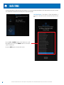
NETWORK
It’s important to verify the information regarding network settings is correct to avoid future site visits. Use this menu to
view and change network configuration.
Wifi Networks. If connected to Wifi, select Wifi
Networks to view available networks.
*See next page for additional information.
Turn Wifi O. If desired it’s possible to toggle ON/OFF
the Wifi connection of this device. Select T u r n W i fi
OFF and press ENTER with the remote to disable Wifi
on this device.
Configure Proxy. See page 12.
If the status indicators for Internet Connection Test
and/or Push are RED, a firewall could be blocking the
connection.
Try testing other Wifi Networks and check with the
network admin to verify that the required URLs have
been white-listed on the network.
For a list of the required URLs consult the Networking
Requirements document which can be found on www.
clintonconnect.com/support
• A hardwired Ethernet connection provides the most reliable and fastest connection. When connected via
Ethernet cable the Ethernet status icon should display GREEN and the Wifi status should display RED.
• Select Turn Wifi OFF if connected to a wired connection and the Ethernet status is RED - Not Connected.
HELPFUL TIPS:

11
Based on Software Version 1.31.1. Content subject to change without notice. Check www.clintonelectronics.com for the most current manual.
NETWORK / Wifi Network
Select the Wifi Networks option from the previous screen and press ENTER on the remote. This will display a list of
available Wifi Networks.
Lock Closed. Indicates that the device does not have
login information for that network
Lock Open. Indicates that the device has the correct
login information for that network. If/when Wifi is
the main network connection type this device will
automatically connect to one of the unlocked networks.
Selecting a Wifi Network with the Lock Open icon
will display the information about that network
and give you the option to Forget or Disconnect
from that selected network.
Forget. Selecting Forget will disconnect from that Wifi
network and remove all login information pertaining to
that network. You will be required to re-enter the login
information if trying to reconnect to this network.
Disconnect. Selecting Disconnect will disconnect
from that Wifi network.
Guest Network (Connected)
Guest Network (Connected)
Guest Network (Connected)
Select Other to manually enter the Wifi name/SSID of
the network you would like to join.
Signal Level indicates the signal strength of the Wifi
connection, this does not indicate internet connection.
It’s possible to be connected to a Wifi network with no
internet access.

12
Based on Software Version 1.31.1. Content subject to change without notice. Check www.clintonelectronics.com for the most current manual.
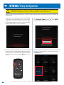
Step 3. If you are configuring the network proxy after
the unit has been on-boarded, (already has a network
connection) begin by pressing the Menu key on the
remote.
Step 1. If you are configuring the network proxy during
on-boarding, start here. Otherwise proceed to Step 3.
Connect to your network via WIFI or ethernet cable.
The PVM will attempt to test the connection, which will
fail because the proxy is not yet configured.
Step 4. Use the arrow keys to move down and select
the Network button.
Step 2. Use the arrow keys on the remote to select
the CONFIGURE PROXY button and press ENTER.
Continue with the instructions at Step 6.
Connect PVMs support network proxies as a means of connecting to the internet. Below are the steps to configure the
network proxy.
ATTENTION: Network Proxy settings must first be configured. If the settings are not set up on the
network before following these steps, the Connect PVM will not connect to the network.
NETWORK / Proxy Configuration

13
Based on Software Version 1.31.1. Content subject to change without notice. Check www.clintonelectronics.com for the most current manual.
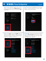
Step 7. Select Back and hit the ENTER button to
complete configuration. While the connection should
automatically establish, you may be required to reboot
the device to complete the connection.
Turn Proxy O. To disable the network proxy setting,
select the Turn Proxy O button from the Proxy
Configuration screen. The device will reboot after
removing the proxy configuration.
NETWORK / Proxy Configuration
Step 6. From the Proxy Configuration screen, use the
remote to set your desired Host, Port, User Name
(optional), and Password (optional).
Step 5. From the Network settings screen, use the
remote to arrow down to the Configure Proxy button
located at the bottom of the screen and press Enter
on the remote.
...Continued

14
Based on Software Version 1.31.1. Content subject to change without notice. Check www.clintonelectronics.com for the most current manual.
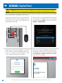
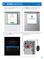
Step 3. Once the PVM has established a connection
to the network, it should automatically detect the
presence of a Captive Portal and redirect to that
screen. *Captive Portal login screens will vary.
Step 1. Connect a USB mouse to one of the USB ports
on the back of the Connect PVM. Confirm that you can
see the mouse cursor on the screen. *USB mouse not
included with Connect PVM.
Step 4. This screen should display a black bar at the
top with the instructions: “Please log in below, then
click DONE when completed.” Below this area will
be the web page consisting of any steps the captive
portal requires for signing in.
Step 2. Connect to the desired wifi network. This may
be done during on-boarding or later via the Network
settings menu (Press Menu on the remote, then select
Network and Wifi Networks).
Connect PVMs support connecting to the internet via a wifi network which employs a Captive Portal. This can be helpful
for use when testing or evaluating the Connect PVM.
Wifi Access
Enter your username and password to connect
to the wireless network.
username
password
Log in
CAMERA
OSD
ON
OFF
DC24V
3. ALARM OUT
4. GND
1. ALARM1
2. GND
NETWORKUSBUSB
ANALOG
OUTPUT
EX-SDI
OUTPUT
ATTENTION: Captive Portals are only recommended for short-term testing and/or product evaluation
as Captive Portals often require periodic re-authentication. A USB mouse is required for these steps.
NETWORK / Captive Portal
Wifi Access
Enter your username and
password to connect
to the wireless network.
johnsmith01
************
Log in
Guest Network

15
Based on Software Version 1.31.1. Content subject to change without notice. Check www.clintonelectronics.com for the most current manual.
NETWORK / Captive Portal
Step 7. Clicking DONE should close this page and
return you to the previous page.
Step 8. Disconnect the mouse from the USB port on
the back of the PVM.
Success!
You are now logged in.
Sign Out
Step 6. After successfully connecting to the network,
click the DONE button in the black bar at the top of the
screen to continue with any additional set up.
Step 5. Use the connected mouse and on-screen
keyboard to complete the required steps and login to
the Captive Portal Wifi network.
Wifi Access
Enter your username and password to connect
to the wireless network.
johnsmith01
************
Log in
Guest Network (Connected)
CAMERA
OSD
ON
OFF
DC24V
3. ALARM OUT
4. GND
1. ALARM1
2. GND
NETWORKUSBUSB
ANALOG
OUTPUT
EX-SDI
OUTPUT
...Continued

16
Based on Software Version 1.31.1. Content subject to change without notice. Check www.clintonelectronics.com for the most current manual.
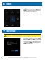
Factory Reset. Using the remote, scroll to Factory
Reset and hit ENTER. Select RESET if you understand
the actions of performing a Factory Reset.
Enter the Factory Reset code (6701) on the screen that
follows. Then select RESET at the bottom and hit the
ENTER button on the remote.
Reboot. Using the remote, scroll to Reboot and hit
ENTER. There will be a small notification at the bottom
of the screen stating “Device will reboot.”
Rebooting the device will not remove any of the
currently assigned advertising content.
Periodically you may need to reboot the device after making system adjustments or if the device appears to be running
slow or experiencing issues.
REBOOT
FACTORY RESET
ATTENTION: Performing a Factory Reset will remove all advertising content, delete any network
settings, and un-associate the device from the company it was assigned to.

17
Based on Software Version 1.31.1. Content subject to change without notice. Check www.clintonelectronics.com for the most current manual.
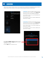
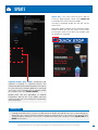
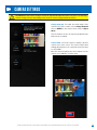
Software Update (Not Shown). Periodically new
software is released to connected devices. The
software update will automatically install on its own. If
for some reason the software update does not install
on its own, or if you would prefer to manually update
the software now, select Software Update.
Update times will vary depending on network
performance and the size of the update. After the
software update has successfully been installed the
device will reboot.
Update Ads. If for some reason the device did not
receive it’s digital signage content, select Update Ads
to manually fetch new content if available.
Selecting to manually update the ads will exit the
menu screen.
During the update, a WHITE cloud icon and percentage
will be shown in the top left corner of the screen.
Accessing the menu screen will not be available until
the update has completed.
54%
UPDATE
• If during the download the cloud icon is RED instead of WHITE, this indicates an error occurred during the
download of the content. Check the Network settings to verify the device can connect to the internet. After
verifying Network settings are correct, try to re-download the deployed content by selecting Update Ads, then
ENTER on the remote.
HELPFUL TIP:

18
Based on Software Version 1.31.1. Content subject to change without notice. Check www.clintonelectronics.com for the most current manual.
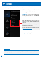
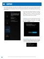
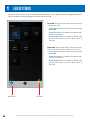
Logs. It may be required when speaking to our technical
support sta to detail some of the most recent data
logged on this device. If connected to the internet
this information can also be accessed remotely by the
admin using the Clinton Connect web app.
SUPPORT
Internet Speed Test. Many problems can be caused by
slow internet download speeds. For best performance
a minimum 2 Mbps download speed is required,
recommended 20 Mbps or faster download speed.
Clear Cache. If experiencing problems with media not
properly deploying or content missing, often clearing
the cache can remedy these problems. Scroll to Clear
Cache and hit ENTER on the remote.
If you are having diculties at any point in the installation process please contact us. We can be reached at 800-549-
6393, Monday~Friday, 8am~5pm CST. Before requesting technical support we suggest trying to reboot the device.
If you’re still experiencing diculties please access the About menu and have the Company name and device serial
number ready.
Page is loading ...
Page is loading ...
Page is loading ...
Page is loading ...
-
 1
1
-
 2
2
-
 3
3
-
 4
4
-
 5
5
-
 6
6
-
 7
7
-
 8
8
-
 9
9
-
 10
10
-
 11
11
-
 12
12
-
 13
13
-
 14
14
-
 15
15
-
 16
16
-
 17
17
-
 18
18
-
 19
19
-
 20
20
-
 21
21
-
 22
22
-
 23
23
-
 24
24


Clinton Electronics CE-P13A-B User manual
- Type
- User manual
- This manual is also suitable for
Ask a question and I''ll find the answer in the document
Finding information in a document is now easier with AI
Related papers
-
Clinton Electronics CE-P13NC-B User manual
-
-
-
-
-
-
-
-
-
Other documents
-
Vista PVM27CAM Installation and User Manual
-
North Star PVM-1 User manual
-
Cisco Systems Visibility Manager 1.0 User manual
-
Toyota EL-731-TMCF Panoramic View Monitor Owner's manual
-
Sony PVM-14L1 User manual
-
Ross GearLite MD DAC-9213-PVM User manual
-
-
 Luoman Koppelo – 24 m² / 70 mm Owner's manual
