INSTALLATION INSTRUCTIONS
CONCENTRIC DIFFUSER
INSTALLATION
INSTRUCTIONS
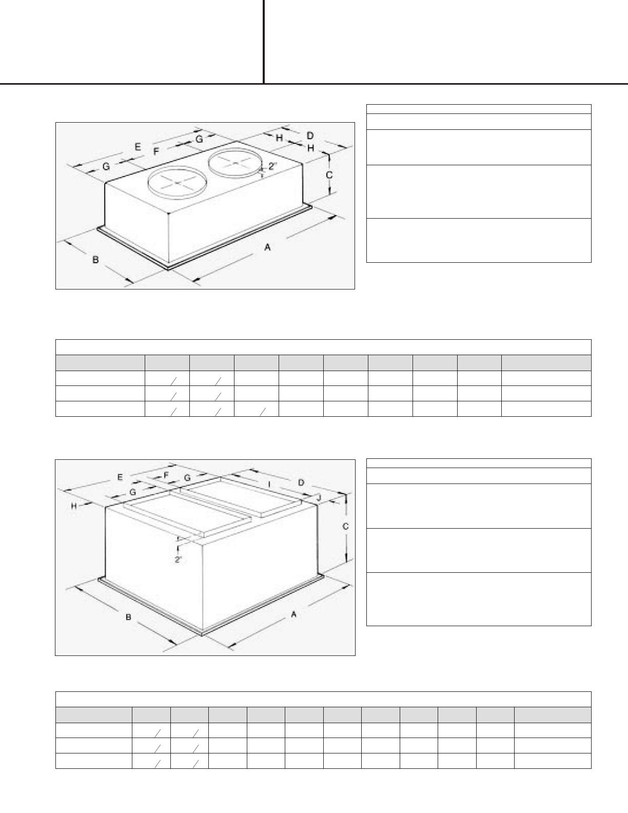
DI MEN SIONAL DATA
MODEL# A B C D E F G H I J DUCT SIZE
547879 47
5
8
35
5
8
23 ¼ 33 45 4 ½ 18 2 ¼ 28 2 ½ 18x28
555637 47
5
8
41
5
8
29 ¼ 39 45 4 ½ 18 2 ¼ 32 3 ¼ 18x32
555638 47
5
8
47
5
8
29 ¼ 45 45 4 ½ 18 2 ¼ 36 4 ½ 18x36
DI MEN SIONAL DATA
MODEL# A B C D E F G H DUCT SIZE
547836 47
5
8
23
5
8
13 ½ 21 45 22 ½ 11 ¼ 10 ½ 16 RD
547837 47
5
8
23
5
8
13 ½ 21 45 22 ½ 11 ¼ 10 ½ 18 RD
547870 47
5
8
29
5
8
16
5
8
27 45 22 ½ 11 ¼ 13 ½ 20 RD
EN GI NEER ING DATA
MODEL# CFM
STATIC
PRES SURE
THROW
FEET
NECK
VEL.
JET VEL.
NOISE
LEVEL
547879
3600 .17 22- 29 844 1646 35
3800 .18 22- 30 891 1737 40
4000 .21 24- 33 938 1829 40
4200 .24 26- 35 985 1920 40
4400 .27 28- 37 1032 2011 40
555637
4600 .31 25- 34 922 1795 40
4800 .32 26- 35 962 1873 40
5000 .34 27- 36 1002 1951 40
5200 .36 30- 39 1043 2029 45
5400 .39 32- 41 1083 2107 45
555638
5600 .36 28- 37 1000 2082 45
5800 .39 29- 38 1036 2156 45
6000 .42 40- 50 1071 2230 45
6200 .46 42- 51 1107 2308 50
6400 .50 43- 52 1143 2379 50
6600 .54 45- 56 1179 2454 50
NOTES:
1. All data is based on the Air Dif fu sion Coun cil guide lines.
2. Throw data is based on Ter mi nal Ve loci ties of 75 FPM us ing
iso ther mal air.
3. Ac tual noise lev els are less than those shown.
EN GI NEER ING DATA
MODEL# CFM
STATIC
PRES SURE
THROW
FEET
NECK
VEL.
JET VEL.
NOISE
LEVEL
547836
600 .09 10- 14 234 417 18
800 .11 12- 18 313 556 20
1000 .14 15- 20 391 694 20
1200 .17 16- 22 469 833 25
547837
1200 .17 16- 22 469 833 25
1400 .20 17- 24 547 972 30
1600 .24 18- 25 625 1111 30
1800 .30 20- 28 703 1250 35
2000 .36 21- 29 781 1389 40
2200 .40 22- 30 859 1528 40
547870
2600 .17 19- 24 663 1294 30
2800 .20 20- 28 714 1393 35
3000 .25 21- 29 765 1492 35
3200 .31 22- 29 816 1592 40
3400 .37 22- 30 867 1692 40
NOTES:
1. All data is based on the Air Dif fu sion Coun cil guide lines.
2. Throw data is based on Ter mi nal Ve loci ties of 75 FPM us ing
iso ther mal air.
3. Ac tual noise lev els are less than those shown.


