Page is loading ...

USER'S
MANUAL
INLINE CENTRIFUGAL FANS IN SOUND-INSULATED CASING
VENTS VS, VENTS VS EC SERIES


TECHNICAL DATA
The unit design is constantly improved, so some models may
slightly differ from the ones depicted herein.
VS and VS EC designation key
Designation key example:
VS 355-4E: inline fan in a sound-insulated casing with a
single-phase four-pole electric motor and a Ø 355 mm impeller.
VS 500 EC: inline fan in a sound-insulated casing with an
EC motor and a Ø500 mm impeller.
Fan type:
VS - inline centrifugal fan with a
sound-insulated casing
Impeller diameter [mm]
315, 355, 400, 450, 500, 560, 630, 710
Motor pole number
4, 6
Power mains parameters:
E - single-phase
D - three-phase
ÕÕ ÕÕÕ - Õ Õ ÅÑ
EC - electronically commutated motor
PURPOSE
The inline centrifugal fan VENTS VS / VENTS VS EC
enclosed in a sound-insulated casing with the intake
spigot diameter from 355 up to 710 mm, hereinafter
the fan, is designed for ventilation of industrial
premises, swimming pools, apartment houses, offices,
hospitals, restaurants and other premises.
Transported air must not contain any dust, solid, sticky
and fibrous substances.
The fan is mounted by means of mounting brackets,
round or square anti-vibration connectors.
The fan is applicable both for supply and extract
ventilation.
The fan is rated for continuous operation always
connected to power mains.
The fan is rated as a class I electric appliance.
Hazardous parts access and water ingress protection
rating is IP X4.

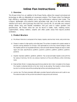
Linear air duct connection
Perpendicular air duct connection
Anti-vibration connector with a square to round reducer
Fig. 1
DELIVERY SET
The delivery set includes:
Fan - 1 item
User's manual
Packing box
SAFETY REQUIREMENTS
Take steps to prevent ingress of smoke, carbon
monoxide and other combustion products into the room
through open chimney flues or other fire-protection
devices. Mounting and maintenance operations must be
performed by duly qualified electricians in compliance
with acting technical regulations.
Disconnect the fan from power supply prior to
maintenance and servicing operations.
Check the fan for any visible damages of the impeller
and the casing before starting installation.
The fan casing must not contain any foreign objects that
could damage the impeller blades.
WARNING
The fan is not rated for operation in an explosive or
inflammable medium.
FAN DESIGN
The special VS fan design enables to change the side
panel positions and direct air flow both straightforward
and perpendicularly at 90°. The VS fans may be used
for construction of various complex ventilation systems.

MOUNTING
The ceiling mounting is performed by means of the
treaded rods fixed in the threaded expansion anchors
(Fig. 2). The fan mounting to the horizontal plane is
shown in Fig. 3.
While mounting the fan ensure sufficient service access
for maintenance and repair operation. The minimum
distance from the fan to the walls is 1 m.
In case of the outdoor fan mounting the fan must be
protected with a protecting hood, as VPR-VS, Fig. 4
and (or) an outer ventilation hood, as KN-VS, Fig. 5.
CONNECTION TO POWER MAINS
CONNECTION TO POWER MAINS SHALL ONLY BE
PERFORMED BY A PROFESSIONAL ELECTRICIAN
AFTER CAREFUL STUDY OF THE PRESENT
USER'S MANUAL.
THE FAN IS ONLY INTENDED FOR AC MAINS
SUPPLYING THE VOLTAGE COMPLIANT WITH THE
TECHNICAL PARAMETER TABLE. CHECK THE
CABLE FOR CHOKING. DO NOT SWITCH ON THE
FAN IF THE CABLE IS DAMAGED.
THE RATED ELECTRIC PARAMETERS OF THE FAN
ARE SHOWN ON THE RATING PLATE.
ANY INTERNAL CONNECTION MODIFICATIONS ARE
NOT ALLOWED AND WILL VOID WARRANTY.
6
1
4
7
2
5
7
2
4
7
3
4
8
4
4
9
4
4
4
9
9
5
Voltage [V]
Circuit breaker
trip current [A]
Wiring diagram
Fig.
230
230
400
230
230
400
230
230
400
400
230
400
400
400
400
400
400
400
400
400
400
400
2
2
1
4
3,15
2
4
4
2
4
6,3
4
3,15
6,3
2
4
8
10
4
4
5
5
Table 1. Technical parameters
Fig. 3
Fig. 2
Fig. 4 Fig. 5
Model
VS 315 EC
VS 355-4E
VS 355-4D
VS 355 EC
VS 400-4E
VS 400-4D
VS 400 EC
VS 450-4E
VS 450-4D
VS 450 EC
VS 500-4E
VS 500-4D
VS 500 EC
VS 560-4D
VS 560-6D
VS 560 EC
VS 630-4D
VS 630Ñ-4D
VS 630-6D
VS 630 EC
VS 630 S EC
VS 710-6D

Connect your fan to power mains in compliance
with a respective wiring diagram number as stated
in the table 1.
The fan is designed for connection to AC single-phase
AC 230 V / 50 Hz or three-phase 400 V / 50 Hz power
mains.
For electric installations use an insulated, durable and
heat-resistant cables with the minimum core cross
section 1 mm2.
The above conductor section value is tentative.
In practice the conductor selection shall be based on the
maximum permissible wire heating depending on the
wire type, its insulation, length and installation method.
Use only copper core wires.
The fan must be properly grounded!
The external power input (230 V/50-60 Hz or
400 V/50-60Hz) must be equipped with an automatic
circuit breaker built into the stationary wiring to disconnect
all the power mains phases. Position of the circuit
breaker QF must ensure free access for quick power-off
of the fan. The trip current must be not less than the
consumption current. The recommended circuit breaker
trip current must exceed the rated consumption current.
The recommended circuit breaker trip current and wiring
diagram number for various fan types are stated in the
table 1.
The recommended wiring diagram example for
connection of the VS fan with a heat protection and a
single-phase motor is shown in the wiring diagram 12
and with three-phase motor is shown in the wiring
diagram 13.
The terminals TW1, TW2 are the normally closed contact
leads of the motor overheating protection. This contact must
be connected in series to the power supply circuit of the coil
of the magnetic starter KM1 that activates the motor after
pressing the button S1. In case of the motor overheating the
contact opens, the starter coil turns off and the motor stops.
The automatic circuit breaker QF, the magnetic starter KM1,
the control buttons S1 and S2 are not included in the delivery
set and must be installed by the user.
The VS EC fans are powered by high-efficient electronically
commutated motors that are featured with high performance
and total controllable speed range.
The maximum EC motor efficiency reaches 90 %.
Connect the VS EC fans to power supply on the terminal
block located in the terminal box in compliance with the
wiring diagram and terminal designations.
The terminal designations are shown on the sticker inside
of the terminal box.

The VS EC are operated via various external control
signals. The fan with EC motor responds to changes
of a control parameter value and delivers required air
flow to the ventilation system.
For instance, the air flow is controlled by means of the
speed controller R-1/010, hereinafter the controller.
The air flow is regulated from zero to the maximum
value depending on the need of ventilation. The speed
controller is not included in the delivery set.
The connection of the speed controller is shown in the
wiring diagrams 6, 7, 10.
The fan may be controlled by means of a CO2 sensor
(the recommended accessories CO2-1 and CO2-2).
The CO2 sensor may be connected either to an
analogue output with the control voltage 0-1 V or to a
discrete output (relay contact). In the first connection
option the fan speed increases as CO2 concentration
rises above the set point and decreases as CO2
concentration drops below the set point.
In the second connection option the normally open
relay contact turns the fan on as CO2 concentration
(ppm) rises above the set point and stops it as CO2
concentration drops down below the set point.
Connect a humidity sensor in the same way.
Connect the external control units with integrated
terminal boxes to the terminal boxes KL3 in compliance
with the terminal designation. The wiring examples are
shown in Fig. 10.
Humidity sensors, differential pressure switches,
CO2 sensors are not included in the delivery set and
must be installed by the user.
L
N
X1
1
2
3
N
L
QF
PE
~230 V
50 Hz
4
ÐÅ
Wiring diagram 1
L
N
X1
1
2
3
N
L
QF
PE
~230 V
50 Hz
5
4
6
T
W1
T
W2
T
W1
T
W2
ÐÅ
Wiring diagram 2
L
N
X1
1
2
3
N
L
QF
PE
~230 V
50 Hz
5
4
T
W1
T
W2
T
W1
T
W2
6
7
ÐÅ
Wiring diagram 3
Connection of other external control units to the fans with
integrated terminal box must be performed in compliance with
performance charts submitted by EC motor manufacturer.
The applied software enables high accuracy control of all
integrated fans, Fig. 11.

Õ2
+10V
CTR
GND
1
2
3
4
5
0-10V
RSB
+10V
RSA
GND
NC
COM
Wiring diagram 8
Õ1
1
2
3
4
PE
L1
L2
5
6
L3
NC
COM
QF
L1
L2
L3
PE
~380 V
50 Hz
Alarm
relay
L2
L1
QF
PE
~400 V
50 Hz
L2
L1
X1
2
7
1
3
L3
L3
5
4
6
V1
U1
W1
W2
PE
U2
V2
L1
L2
L3
8
9
T
W2
T
W1
T
W1
T
W2
T
W1
T
W2
ÐÅ
Wiring diagram 4
L2
L1
QF
PE
~400 V
50 Hz
L2
L1
X1
2
7
1
3
L3
L3
5
4
6
V1
U1
W1
W2
PE
U2
V2
L1
L2
L3
8
9
T
W2
T
W1
T
W1
T
W2
T
W1
T
W2
ÐÅ
Wiring diagram 5
L
QF
~230 V
50 Hz
N
L
X1
2
1
3
PE
N
PE
+10V
0-10V
GND
+10V
CTR
GND
Recommended
speed controller
VENTS R-1/010
X2
1
2
3
Wiring diagram 6
Wiring diagram 7
QF
PE
N
L
Õ1
~230 V
50/60 Hz
1
2
3
4
5
PE
N
L
Õ2
+10V
CTR
GND
1
2
3
4
5
0-10V
RSB
+10V
RSA
GND
Recommended
speed controller
VENTS R-1/010
Recommended
speed controller
VENTS R-1/010
Alarm
relay

KL1
PE
L3
~400 V
50 Hz
QF
KL3
+20 Â
0-10 Â
RSA
RSB
RSA
RSB
GND
4-20 mA
+10 Â
0-10 Â
GND
OUT
Interface
RS485
GND
Control input
GND
External speed
controller power
supply, max. 10 mA
External sensor power
supply, max. 50 mA
Control output
KL2
NO
COM
NC
Alarm relay
Normally open
contact
com
L1
L2
L2
L1
L3
PE
Wiring diagram 9
Connection of analogue 0-10 V
output of a control unit
Unit
0-10 V GND
KL3
Wiring example for connection
of various control units to
EC motors
Connection of relay output
of a control unit
0-10 V +10 V
KL3
KL3
Connection of a speed controller
(potentiometer)
0-10 V
GND
+10 V
Connection of a 4-20 mA
pressure sensor
4-20 ìÀ +20 V
KL3
Wiring diagram 10
Control input
Control input
Normally closed
contact
Unit Unit

External wiring diagram for integration of EC motor fans in the group
Power mains
50/60 Hz
Wiring diagram 11
Computer with an
interface converter (RS 486)
Pressure sensor Alarm relay
Power mains
50/60 Hz
Power mains
50/60 Hz

L
N
X1
1
2
3
L
QF
N
PE
TW1
4
5
6
TW2
~230 V
50 Hz
KM1
S1
“ON”
S2
“OFF”
KM1
ÐÅ
L1
TW1
TW2
S1
“ON”
S2
“OFF”
KM1
L2
L3
QF
~400 V
50 Hz
L1
L2
L3
N
PE
PE
Fan
Wiring diagram 13Wiring diagram 12

TROUBLESHOOTING
Faults and troubleshooting
Problem
Possible reasons Troubleshooting
The fan does not start up
during the ventilator start-up.
No power supply.
Make sure that the fan is properly connected
to the power mains and make any
corrections, if necessary.
Motor jam.
Turn the fan off.
Troubleshoot the motor jam.
Restart the ventilator.
Automatic circuit breaker
tripping during the
fan activation.
Overcurrent resulted from short
circuit in the electric circuit.
Turn the fan off.
Contact the product seller for
troubleshooting.
Noise, vibration
Impeller blades are clogged.
Clean the fan impeller.
Loose screw connection. Check and tighten the screws if required.

MAINTENANCE
Disconnect the fan from power supply prior to any maintenance operations. The fan maintenance includes regular cleaning
of the fan surfaces of dirt and dust. Use a soft dry brush or compressed air to remove dust.
Clean the impeller blades once in 6 months. To clean the fan blades remove the screws take off the fan cover, clean the
impeller blades using a detergent solution. Avoid water splashes on the fan motor!
STORAGE AND TRANSPORTATION REGULATIONS
Store the fan in the manufacturer's original packing box in a dry ventilated premise at ambient temperatures from +10 °C up to
+ 40 °C. Storage environment must not contain aggressive vapours and chemical mixtures provoking corrosion, insulation and
sealing deformation.Use suitable hoist machinery for handling and storage operations to prevent possible damage to the fan.
Follow the handling requirements applicable for the particular type of cargo. The fan can be carried in the original packing
by any mode of transport provided proper protection against precipitation and mechanical damage.
Avoid sharp blows, scratches or rough handling during loading and unloading.
MANUFACTURER'S WARRANTY
The manufacturer hereby warrants normal operation of the fan for 2 years after the retail sale date provided the user's
observance of the transportation, storage, mounting and operation regulations.
In case of no sales date marking calculation of the warranty period starts from the manufacture date.
In case of any operating malfunctions during the warranty period a warranty claim must be submitted with a technical evaluation
report with a detailed fault description.
The fan damages resulting from unauthorized tampering with the circuit diagram shall not be considered as a warranty case.
For warranty and post-warranty service contact the manufacturer or the fan seller. In case of a warranty claim this user's
manual with the Seller's stamp must also be submitted. The warranty and post-warranty service is performed at the
manufacturing facility.

SELLER INFORMATION
Seller
Address
Phone Number
E-mail
Purchase Date
This is to certify acceptance of the complete fan delivery with the user's manual.
The warranty terms are acknowledged and accepted.
Customer's
Signature
Seller's Stamp
Unit Type Inline centrifugal fan in sound-insulated casing
Model VENTS VS, VENTS VS EC Series
Serial Number
Manufacture Date
Is compliant with the technical specifications and is recognized as serviceable.
We hereby declare that the product complies with the essential protection requirements of Electromagnetic Council Directive
2004/108/EC, 89/336/EEC and Low Voltage Directive 2006/95/EC, 73/23/EEC and CE-marking Directive 93/68/EEC on the
approximation of the laws of the Member States relating to electromagnetic compatibility.
This certificate is issued following test carried out on samples of the product referred to above.
Quality
Inspector's
Stamp
ACCEPTANCE CERTIFICATE

WARRANTY CARD
Unit Type
Inline centrifugal fan in sound-insulated casing
Model
VENTS VS, VENTS VS EC Series
Serial Number
Manufacture Date
Purchase Date
Warranty Period
Seller
INSTALLATION CERTIFICATE
The inline centrifugal fan in sound-insulated casing VENTS VS, VENTS VS EC
has been connected to power mains pursuant to the requirements stated in the
present user's manual.
Company Name
Address
Phone Number
Installation Technician's
Full Name
Installation Date: Signature:
The fan has been installed in accordance with the provisions of all the applicable
local and national construction, electrical and technical codes and standards.
The fan operates normally as intended by the manufacturer.
Signature:
Installation
Company Stamp
Seller's Stamp

V19 -0EN 4
/