Vents TT-M, TT-MD, TT-MD EC, TT Silent-M, TT Silent-MD, TT Silent-MD EC User manual
- Type
- User manual

USER’S MANUAL
Inline mixed-flow fan
TT-M
TT-MD
TT-MD EC
TT Silent-M
TT Silent-MD
TT Silent-MD EC

www.ventilation-system.com
2
TT (Silent) M(D) inline fan
This user’s manual consisting of the technical details, operating instructions and technical specification covers the installation and mounting of the TT (Silent)
M(D) inline mixed-flow fan (hereinafter referred to as «the fan» or «the unit» as mentioned in the «Safety requirements» and «Manufacturer’s warranty»
sections as well as in warnings and information blocks).
CONTENTS
Safety requirements ....................................................................................................................................2
Purpose ...............................................................................................................................................................4
Delivery set ....................................................................................................................................................... 4
Designation key ............................................................................................................................................. 4
Technical data ................................................................................................................................................. 5
Unit design and operating logic .........................................................................................................7
Mounting and set-up ................................................................................................................................. 7
Connection to power mains and control ................................................................................... 10
Technical maintenance ..........................................................................................................................12
Troubleshooting .........................................................................................................................................12
Storage and transportation regulations ......................................................................................13
Manufacturer’s warranty ....................................................................................................................... 13
Acceptance certificate ...........................................................................................................................14
Seller information ...................................................................................................................................... 14
Installation certificate ..............................................................................................................................14
Warranty card ...............................................................................................................................................14
Read the user’s manual carefully prior to installing and operating the unit.
Fulfil the user’s manual requirements as well as the provisions of all the applicable local and national construction, electrical and technical norms and
standards.
The warnings contained in the user’s manual must be considered most seriously since they contain vital personal safety information.
Failure to follow the rules and safety precautions noted in this user’s manual may result in an injury or unit damage.
After a careful reading of the manual, keep it for the entire service life of the unit.
While transferring the unit control the user’s manual must be turned over to the receiving operator.
Symbol legend:
WARNING!
DO NOT!
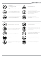
SAFETY REQUIREMENTS
UNIT MOUNTING AND OPERATION SAFETY PRECAUTIONS
• Disconnect the unit from power mains prior to
any installation operations.
• The unit must be grounded!
• Do not lay the power cable of the unit in close
proximity to heating equipment.
• While installing the unit follow the safety
regulations specific to the use of electric tools.

www.ventilation-system.com
3
UNIT MOUNTING AND OPERATION SAFETY PRECAUTIONS
• Do not allow children to operate the unit.
• Disconnect the unit from power mains prior to
any technical maintenance.
• Do not store any explosive or highly flammable
substances in close proximity to the unit.
• When the unit generates unusual sounds, odour
or emits smoke disconnect it from power supply
and contact the Seller.
• Do not open the unit during operation.
• Do not direct the air flow produced by the unit
towards open flame or ignition sources.
• Do not block the air duct when the unit is
switched on.
• In case of continuous operation of the unit
periodically check the security of mounting.
• Do not sit on the unit and avoid placing foreign
objects on it.
• Use the unit only for its intended purpose.
• Do not change the power cable length at your
own discretion.
• Do not bend the power cable.
• Avoid damaging the power cable.
• Do not put any foreign objects on the power
cable.
• Unpack the unit with care.
• Do not use damaged equipment or cables
when connecting the unit to power mains.
• Do not operate the unit outside the
temperature range stated in the user’s manual.
• Do not operate the unit in aggressive or
explosive environments.
• Do not touch the unit controls with wet hands.
• Do not carry out the installation and
maintenance operations with wet hands.
• Do not wash the unit with water.
• Protect the electric parts of the unit against
ingress of water.

www.ventilation-system.com
4
TT (Silent) M(D) inline fan
The fan is designed for ventilation of various industrial premises, swimming pools, apartment houses, offices, hospitals, restaurants and other premises.
The Silent models are intended for supply and exhaust ventilation systems of different commercial and industrial premises with high demands on noise
level (libraries, conference halls, educational institutions, kindergartens etc.)
The unit is a component part and is not designed for independent operation.
PURPOSE
The fan is designed for floor, suspended or ceiling mounting.
The unit is rated for continuous operation.
Transported air must not contain any flammable or explosive mixtures, evaporation of chemicals, sticky substances, fibrous materials, coarse dust, soot
and oil particles or environments favourable for the formation of hazardous substances (toxic substances, dust, pathogenic germs).
THE UNIT MAY NOT BE OPERATED BY CHILDREN OR PERSONS WITH REDUCED PHYSICAL, MENTAL
OR SENSORY CAPACITIES, OR LACKING THE APPROPRIATE TRAINING.
THE UNIT MUST BE INSTALLED AND CONNECTED ONLY BY PROPERLY QUALIFIED PERSONNEL
AFTER THE APPROPRIATE BRIEFING.
THE CHOICE OF UNIT INSTALLATION LOCATION MUST PREVENT UNAUTHORIZED ACCESS BY
UNATTENDED CHILDREN.
DELIVERY SET
Name Number
Fan 1 item
User's manual 1 item
Packing box 1 item
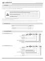
DESIGNATION KEY
TT Silent M D XXX - X X
Motor phases:
E – single-phase
D – three-phase
Casing material
M – metal
Casing design
_ – without sound insulation
Silent – sound-insulated
Fan model
Number of motor poles
Spigot connecting diameter [mm]
Motor model:
_ – basic motor
D – energy efficient motor
TT Silent M D XXX - X EC
Casing material
M – metal
Casing design
_ – without sound insulation
Silent – sound-insulated
Fan model
Motor type:
EC – synchronous electronically commutated motor
Spigot connecting diameter [mm]
Motor model:
D – energy efficient motor
Motor phases:
1 – single-phase
3 – three-phase
Fans with AC-motors
Fans with EC-motors

www.ventilation-system.com
5
TECHNICAL DATA
The fan is designed for indoor application with the ambient temperature ranging from +1 °C up to +40 °C and relative humidity up to 80 %.
The transported air temperature depends on the fan model (see the table with technical data).
Ingress Protection (IP) rating from solid objects and liquids IPX4.
The fan design is constantly being improved, so some models can slightly differ from those ones described in this manual.
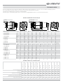
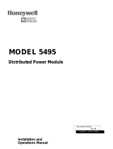
B1
L3 L3
B H
ØD ØD
K DK
TT M(D)
ØD K
B1
B
L L1L2
H
ØD DK
TT Silent M(D)
Model B B1 D DK H K L L1 L2 L3 Weight [kg]
TT Silent-MD 355-4E 1070 60 353 510 540 360 338 60 60 - 35
TT Silent-MD 400-4E 1350 60 397 565 595 450 485 60 60 - 45
TT Silent-MD 450-4E 1300 60 447 705 730 540 442 70 90 - 59
TT - MD 355-4E 685 60 353 605 515 576 - - - 60 25
TT - MD 400-4E 740 60 397 665 570 633 - - - 60 30
TT - MD 450-4E 900 60 447 800 705 770 - - - 90 45
TT - MD 500-4E 900 60 497 815 720 785 - - - 90 55
TT - MD 500-4D 900 60 497 815 720 785 - - - 90 51
TT Silent-MD 355-1 EC 1070 60 353 510 540 360 338 60 60 - 35
TT Silent-MD 400-1 EC 1350 60 397 565 595 450 485 60 60 - 45
TT Silent-MD 450-1 EC 1300 60 447 705 730 540 442 70 90 - 54
TT Silent-MD 450-3 EC 1300 60 447 705 730 540 442 70 90 - 55
TT - MD 355-1 EC 685 60 353 605 515 576 - - - 60 25
TT - MD 400-1 EC 740 60 397 665 570 633 - - - 60 27
TT - MD 450-1 EC 900 60 447 800 705 770 - - - 90 40
TT - MD 450-3 EC 900 60 447 800 705 770 - - - 90 42
TT - MD 500-1 EC 900 60 497 815 720 785 - - - 90 43
TT - MD 500-3 EC 900 60 497 815 720 785 - - - 90 43
Model B B1 D DK H K L L1 L2 L3 Weight [kg]
TT Silent-M 355-4E 1320 80 353 510 540 460 540 60 60 - 33
TT Silent-M 355-4D 1320 80 353 510 540 460 540 60 60 - 33
TT Silent-M 400-4E 1320 80 397 510 540 460 540 60 60 - 35
TT Silent-M 400-4D 1320 80 397 510 540 460 540 60 60 - 35
TT Silent-M 450-4E 1425 80 447 610 640 460 640 60 60 - 51
TT Silent-M 450-4D 1425 80 447 610 640 460 640 60 60 - 51
TT - M 355-4E 825 80 353 605 515 575 - - - 60 22
TT - M 355-4D 825 80 353 605 515 575 - - - 60 22
TT - M 400-4E 825 80 397 605 515 575 - - - 60 24
TT - M 400-4D 825 80 397 605 515 575 - - - 60 24
TT - M 450-4E 975 80 447 705 610 675 - - - 60 35
TT - M 450-4D 975 80 447 705 610 675 - - - 60 35
TT - M 500-4D 1120 100 497 805 710 775 - - - 90 44
OVERALL DIMENSIONS OF THE FAN, MM
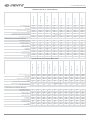
TECHNICAL DATA OF TT SILENT M FANS
TT Silent-M 355-4E
TT Silent-M 355-4D
TT Silent-M 400-4E
TT Silent-M 400-4D
TT Silent-M 450-4E
TT Silent-M 450-4D
TT-M 355-4E
TT-M 355-4D
TT-M 400-4E
TT-M 400-4D
TT-M 450-4E
TT-M 450-4D
TT-M 500-4D
Unit voltage [V /50-60 Hz] 1~ 230 3~ 400 1~ 230 3~ 400 1~ 230 3~ 400 1~ 230 3~ 400 1~ 230 3~ 400 1~ 230 3~ 400 3~ 400
Power [W] 578 585 580 590 1200 1230 578 585 580 590 1200 1230 2125
Current [A] 3.42 1.77 3.43 1.78 7.72 3.43 3.42 1.77 3.43 1.78 7.72 3.43 4.68
Maximum air capacity [m
3
/h] 3310 3430 3545 3670 6260 6510 3340 3480 3610 3740 6385 6635 11900
RPM 1480 1490 1480 1490 1475 1490 1480 1490 1480 1490 1475 1490 1455
Sound pressure level at 3 m distance [dB(A)]
49 49 50 50 59 59 57 57 58 58 65 65 73
Maximum transported air temperature [°C]
from -25 up to +60
Ingress protection rating IPX4 IPX4 IPX4 IPX4 IPX4 IPX4 IPX4 IPX4 IPX4 IPX4 IPX4 IPX4 IPX4

www.ventilation-system.com
6
TT (Silent) M(D) inline fan
TECHNICAL DATA OF TT SILENT MD FANS
TT Silent-MD 355-4E
TT Silent-MD 400-4E
TT Silent-MD 450-4E
TT - MD 355-4E
TT - MD 400-4E
TT - MD 450-4E
TT - MD 500-4E
TT - MD 500-4D
Unit voltage [V /50 Hz] 1~ 230 1~ 230 1~ 230 1~ 230 1~ 230 1~ 230
1~ 230
3~ 400
Power [W] 310 460 910 310 460 910 1450 1350
Current [A] 1.35 2 4.4 1.35 2 4.4 6.1 2.3
Maximum air capacity [m
3
/h] 3200 4310 6050 3250 4400 6200 8750 9450
RPM 1390 1340 1330 1390 1340 1330 1310 1320
Sound pressure level at 3 m distance [dB(A)]
47 51 59 55 57 64 67 68
Maximum transported air temperature [°C]
from -25 up to +60
Ingress protection rating IPX4 IPX4 IPX4 IPX4 IPX4 IPX4 IPX4 IPX4
Technical data at maximum eciency:
Overall efficiency (η) [%] 29.7 31.9 34.7 30.6 33.2 35.8 36.3 39.4
Measurement category A A A A A A A A
Efficiency category Static Static Static Static Static Static Static Static
Efficiency grade 46.8 46.8 47 47.7 48 47.9 46 49.3
Variable speed drive No No No No No No No No
Power [kW] 0.235 0.385 0.684 0.239 0.389 0.693 1.185 1.15
Current [A] 1.13 1.7 3.44 1.13 1.7 3.45 5.1 2.2
Air capacity [m
3
/h] 1748 2054 3116 1782 2091 3157 4710 4805
Static pressure [Pa] 141 211 269 145 218 277 322 333
RPM 1405 1350 1365 1410 1360 1380 1350 1380
Specific ratio 1 1 1 1 1 1 1 1
TECHNICAL DATA OF TT SILENT MD EC FANS
TT Silent-MD 355-1 EC
TT Silent-MD 400-1 EC
TT Silent-MD 450-1 EC
TT Silent-MD 450-3 EC
TT - MD 355-1 EC
TT - MD 400-1 EC
TT - MD 450-1 EC
TT - MD 450-3 EC
TT - MD 500-1 EC
TT - MD 500-3 EC
Unit voltage [V /50-60 Hz]
1~ 200-277 1~ 200-277 1~ 200-277 3~ 380-480 1~ 200-277 1~ 200-277 1~ 200-277 3~ 380-480 1~ 200-277 3~ 380-480
Power [W] 460 380 1250 2100 460 380 1250 2100 1050 2050
Current [A] 2.5 2.1 6.3 3.5 2.5 2.1 6.3 3.5 5.4 3.3
Maximum air capacity [m
3
/h] 4000 4370 7650 8920 4080 4480 7830 9160 8600 11100
RPM 1700 1290 1530 1900 1700 1290 1530 1900 1290 1600
Sound pressure level at 3 m distance [dB(A)]
52 55 54 57 61 63 63 69 65 71
Maximum transported air temperature [°C]
from -25 up to +40
Ingress protection rating IPX4 IPX4 IPX4 IPX4 IPX4 IPX4 IPX4 IPX4 IPX4 IPX4
Technical data at maximum eciency:
Overall efficiency (η) [%] 43.1 40.4 40.9 44.1 43.3 41.8 41.5 44.9 42.8 41.0
Measurement category A A A A A A A A A A
Efficiency category Static Static Static Static Static Static Static Static Static Static
Efficiency grade 58.7 55.8 50.7 51.6 58.7 57.1 51.2 52.2 53.2 48.4
Variable speed drive Yes Yes Yes Yes Yes Yes Yes Yes Yes Yes
Power [kW] 0.325 0.341 1.158 1.948 0.339 0.352 1.195 2.016 1.005 1.994
Current [A] 1.45 1.51 5.84 3.45 1.46 1.52 5.85 3.47 5.2 3.29
Air capacity [m
3
/h] 1756 2054 3844 5514 1785 2120 3936 5663 4630 5495
Static pressure [Pa] 251 211 401 515 259 219 411 529 301 492
RPM 1700 1420 1530 1900 1700 1430 1530 1900 1290 1610
Specific ratio 1 1 1 1 1 1 1 1 1 1

www.ventilation-system.com
7
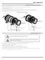
UNIT DESIGN AND OPERATING LOGIC
The unit is an inline mixed-flow fan.
The fan casing is made of sheet steel (using heat- and sound-insulation material for the Silent models).
Connection spigots are round.
The fan is equipped with a motor which has an impeller with diagonal blades.
The motor has thermal relays built into the motor winding for overheating protection (TW). The relays must always be connected.
Use of the motor with ball bearings with specially selected grease ensures low-noise, maintenance-free operation of the fan.
The air flow direction is indicated by the arrow on the fan casing.
Fan casing
Impeller
Sound insulation
material
Fan casing
Air intake
Air
intake
Air exhaust
Air exhaust
TT Silent M(D) TT M(D)
Motor
The TT MD fans are equipped with a
noise-absorbing housing
Impeller
Motor
The TT Silent MD fans are equipped
with a noise-absorbing housing
UNIT DESIGN AND OPERATING LOGIC
MOUNTING AND SETUP
The TT M(D) fan is suspended to the mounting surface through the threaded rod fixed inside the expansion anchor.
The TT Silent M(D) is suitable both for horizontal and vertical installation using a fixing bracket.
The fan is intended for mounting to round air ducts.
The fans are installed between the air ducts.
The casing is equipped with fixing brackets for easier installation of the fan.
While installing the unit ensure convenient access for subsequent maintenance and repair.
Fasteners for fan mounting are not included in the delivery set and should be ordered separately.
While choosing fasteners consider the material of the mounting surface as well as the weigh of the unit, refer to the Technical Data section.
Fasteners for unit mounting should be selected by the service technician.
THE UNIT MUST BE MOUNTED BY A QUALIFIED EXPERT ONLY, PROPERLY TRAINED AND HAVING
THE REQUIRED TOOLS AND MATERIALS.
READ THE USER’S MANUAL PRIOR TO MOUNTING THE UNIT.

www.ventilation-system.com
8
TT (Silent) M(D) inline fan
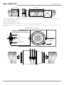
min 800 mm
Nut
WARNING! fastening elements are
not included in the scope of delivery!
Washer
Vibration absorbing
rubber
Washer
Nut and lock nut
Threaded rod
Access
to the terminal
box
MOUNTING OF THE TTMD FAN
To attain the best performance of the fan and to minimise turbulence-induced air pressure losses connect the straight air duct section to the spigots
on both sides of the unit while mounting.
Minimum straight air duct length:
• equal to 1 air duct diameter on intake side
• equal to 3 air duct diameters on outlet side
If the air ducts are too short or not connected, protect the unit parts from ingress of foreign objects.
To prevent uncontrollable access to the fan the spigots may be covered with a protecting grille or other protecting device with mesh width not more
than 12.5 mm.
1 x D 3 x D

www.ventilation-system.com
9
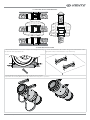
TT SILENT MD INSTALLATION
1. Unscrew the bolts that connect the clamp to the fixing bracket using
the wrench of the appropriate size.
2. Secure the brackets to the surface using screws with dowels of the
appropriate size (not included in the scope of delivery).
3. Secure the fan on the bracket with clamps and bolts removed earlier.
Suspend the fan carefully. Make sure the fan is fastened securely prior to operation.
TT SILENT MD INSTALLATION METHODS

www.ventilation-system.com
10
TT (Silent) M(D) inline fan
DISCONNECT THE UNIT FROM POWER MAINS PRIOR TO ANY OPERATIONS. THE FAN MUST
BE CONNECTED TO POWER MAINS BY A QUALIFIED ELECTRICIAN. THE RATED ELECTRICAL
PARAMETERS OF THE UNIT ARE GIVEN ON THE MANUFACTURER’S LABEL.
ANY INTERNAL CONNECTION MODIFICATIONS ARE NOT ALLOWED AND RESULT IN
WARRANTY LOSS.
CONNECTION TO POWER MAINS AND CONTROL
The fan is rated for connection to single-phase or three-phase AC power mains with a voltage of 230 V or 400 V according to the wiring diagrams below.
The terminal designation is placed inside of the terminal box.
The terminal clamp marking corresponds to the marking on the wiring diagram.
Connect the fan to power mains by means of insulated, durable and thermal-resistant cords (cables, wires) with appropriate cross section.
The cables are routed into the terminal box through a sealed lead-in for electrical hazard class compliance.
The fan shall be connected to power supply through the external circuit breaker with a thermal-magnetic trip. The rated current of the circuit breaker
must be not below the rated current consumption.
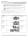
FAN MODEL
EXTERNAL CONNECTIONS DIAGRAM
TT Silent-M 355-4E
TT Silent-M 400-4E
TT Silent-M 450-4E
TT - M 355-4E
TT - M 400-4E
TT - M 450-4E
L
N
PE
L
N
PE
QF
Power
1~230 V / 50 Hz
PE – protective grounding.
N – power supply neutral.
L – power supply phase.
QF – circuit breaker.
TT Silent-M 355-4D
TT Silent-M 400-4D
TT Silent-M 450-4D
TT - M 355-4D
TT - M 400-4D
TT - M 450-4D
TT - M 500-4D
L1
L3
L2
L1
L3
L2
PEPE
QF
Power
3~400 V / 50 Hz
PE – protective grounding.
N – power supply neutral.
L1, L2, L3 – power supply phase.
QF – circuit breaker.
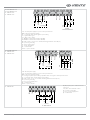
TT Silent-MD 355-4E
TT Silent-MD 400-4E
TT Silent-MD 450-4E
TT - MD 355-4E
TT - MD 400-4E
TT - MD 450-4E
TT - MD 500-4E
PE
L
N
T2
T1
L2
L1
1411
PE
S2 «OFF»
S1 «ON»
L
N
TW2
TW1
KM1
QF
Power
1~230 V / 50 Hz
PE – protective grounding.
N – power supply neutral.
L – power supply phase.
QF – circuit breaker.
TW1, TW2 – thermal contacts
of the motor.
KM1 – motor starter.
S1 – «Start» button.
S2 – «Stop» button.

www.ventilation-system.com
11
TT Silent-MD 355-1 EC
TT Silent-MD 400-1 EC
TT - MD 355-1 EC
TT - MD 400-1 EC
10V
GND
E1
10V
GND
R-1/010
E1
D1
A1
A
B
RC(11)
RC(14)
PE
N
L1
PE
N
L1
QF
Power
1~230 V 50/60 Hz
10V – 10 V DC power supply for a speed control potentiometer.
GND – DC power supply grounding.
E1 – 0-10 V input direct current signal for speed setting.
D1 – digital enable signal.
A1 – status / tacho output.
A – MODBUS communication interface (RS-485).
B – MODBUS communication interface (RS-485).
RC – NO-contact is closed in case of alarm (switching parameters: 250 V AC, 2 A).
PE – protective grounding.
N – power supply neutral.
L1 - power supply phase.
QF – circuit breaker.
R1/010 – speed controller.
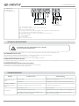
TT Silent MD 450-3 EC
TT - MD 450-3 EC
TT - MD 500-3 EC
24V
10V
GND
D1
E1
10V
GND
CRT
RC(11)
RC(14)
PE
L3
L2
L1
PE
L3
L2
L1
R-1/010
QF
Power
3~400 V 50/60 Hz
24V – 24 V DC power supply.
10V – 10 V DC power supply for a speed control potentiometer.
GND – DC power supply grounding.
D1 – analogue input for speed setting compatible with 0-10 V signal or external potentiometer.
E1 – 0-10 V input direct current signal for speed setting.
RC – NO-contact closes in case of alarm (switching parameters: 250 V AC, 2 A).
PE – protective grounding.
L1, L2, L3 – power supply phase.
QF – circuit breaker.
R1/010 – speed controller.
TT - MD 500-4D
V1
W1
PE
L2
L3
PE
U1L1
W2
U2
V2
TW1
TW2
QF
Power
3~400 V 50 Hz
W1, W2, U1,U2, V1, V2 – contacts for motor
connection.
TW1, TW2 – motor thermal contacts.
PE – protective grounding.
L1, L2, L3 – power supply phase.
QF - circuit breaker.

www.ventilation-system.com
12
TT (Silent) M(D) inline fan
TECHNICAL MAINTENANCE
DISCONNECT THE UNIT FROM POWER SUPPLY BEFORE
ANY MAINTENANCE OPERATIONS.
The unit must undergo technical maintenance once a year. Technical maintenance includes regular cleaning of the unit.
1. Fan maintenance (once a year).
Some dust may accumulate on the impeller blades or on the fan motor which reduces the unit capacity.
Clean the fans with a soft brush, cloth, vacuum cleaner or compressed air.
Do not use water, aggressive solvents or sharp objects as they may damage the impeller.
2. Supply air ow control (twice per year).
The supply duct grille may get clogged with leaves and other objects reducing the unit performance and supply air delivery. Check the supply grille twice
per year and clean it as required.
3. Technical maintenance of air duct system (every 5 years).
Some dust may accumulate inside the air ducts which reduces the unit capacity.
Duct maintenance means regular cleaning or replacement.
TROUBLESHOOTING
Problem Possible reasons Troubleshooting
The fan(s) do(es) not get
started.
No power supply.
Make sure the power supply line is connected correctly, otherwise
troubleshoot a connection error.
Jammed motor. Turn off the fan. Troubleshoot the motor jamming. Restart the fan.
Automatic circuit breaker
tripping following the fan
turning on
High current consumption due to short circuit in power line. Turn off the fan. Contact the Seller.
Noise, vibration
The fan impeller is soiled. Clean the impellers.
The fan or casing screw connection is loose. Tighten the screw connection of the fan or the casing against stop.
The ventilation system components (air ducts, diffusers, louvre
shutters, grilles) are clogged or damaged.
Clean or replace the ventilation system components (air ducts,
diffusers, louvre shutters, grilles).
TT - MD 450-1 EC
TT - MD 500-1 EC
TT Silent-MD 450-1 EC
Power
1~230 V 50/60 Hz
24V – 24 V DC power supply.
10V – 10 V DC power supply for a speed control potentiometer.
GND – DC power supply grounding.
D1 – analogue input for speed setting compatible with 0-10 V signal or external potentiometer.
E1 – 0-10 V input direct current signal for speed setting.
RC – NO-contact closes in case of alarm (switching parameters: 250 V AC, 2 A).
PE – protective grounding.
L1 – power supply phase.
QF – circuit breaker.
R1/010 – the speed controller.

www.ventilation-system.com
13
The manufacturer hereby warrants normal operation of the unit for 24 months after the retail sale date provided the user’s observance of the transportation,
storage, mounting and operation regulations.
Should any malfunctions occur in the course of the unit operation through the Manufacturer’s fault during the guaranteed period of operation the user is
entitled to elimination of faults by the manufacturer by means of warranty repair at the factory free of charge.
The warranty repair shall include work specific to elimination of faults in the unit operation to ensure its intended use by the user within the guaranteed
period of operation.
The faults are eliminated by means of replacement or repair of the unit components or a specific part of such unit component.
The warranty repair does not include:
• routine technical maintenance
• unit installation/dismantling
• unit setup
To benefit from warranty repair the user must provide the unit, the user’s manual with the purchase date stamp and the payment document certifying
the purchase.
The unit model must comply with the one stated in the user’s manual.
Contact the Seller for warranty service.
The manufacturer’s warranty does not apply to the following cases:
• User’s failure to submit the unit with the entire delivery package as stated in the user’s manual including submission with missing component parts
previously dismounted by the user.
• Mismatch of the unit model and the brand name with the information stated on the unit packing and in the user’s manual.
• User’s failure to ensure timely technical maintenance of the unit.
• External damage to the unit casing (excluding external modifications as required for installation) and internal components caused by the user.
• Redesign or engineering changes to the unit.
• Replacement and use of any assemblies, parts and components not approved by the manufacturer.
• Unit misuse.
• User’s violation of the unit installation regulations.
• User’s violation of the unit control regulations.
• Unit connection to the power mains with a voltage different from the one stated in the user’s manual.
• Unit breakdown due to voltage surges in the power mains.
• Discretionary repair of the unit by the user.
• Unit repair by any persons without the manufacturer’s authorization.
• Expiration of the unit warranty period.
• User’s violation of the unit transportation regulations.
• User’s violation of the unit storage regulations.
• Wrongful actions against the unit committed by third parties.
• Unit breakdown due to circumstances of insuperable force (fire, flood, earthquake, war, hostilities of any kind, blockades).
• Missing seals if provided by the user’s manual.
• Failure to submit the user’s manual with the unit purchase date stamp.
• Missing payment document certifying the unit purchase.
MANUFACTURER’S WARRANTY
FOLLOWING THE REGULATIONS STIPULATED HEREIN WILL ENSURE A LONG AND TROUBLEFREE
OPERATION OF THE UNIT.
USERS’ WARRANTY CLAIMS SHALL BE SUBJECT TO REVIEW ONLY UPON PRESENTATION
OF THE UNIT, THE PAYMENT DOCUMENT AND THE USER’S MANUAL
WITH THE PURCHASE DATE STAMP.
STORAGE AND TRANSPORTATION REGULATIONS
Store the unit in the manufacturer’s original packing box in a dry closed ventilated premise with temperature range from +5 °C to + 40 °C.
Storage environment must not contain aggressive vapours and chemical mixtures provoking corrosion, insulation and sealing deformation.
Use suitable hoist machinery for handling and storage operations to prevent possible damage to the unit.
Follow the handling requirements applicable for the particular type of cargo.
The unit can be transported in the original packing by any mode of transport without limitation provided proper protection against precipitation and
mechanical damage.
Avoid sharp blows, scratches or rough handling during transportation, loading and unloading.

www.ventilation-system.com
14
TT (Silent) M(D) inline fan
ACCEPTANCE CERTIFICATE
INSTALLATION CERTIFICATE
WARRANTY CARD
Unit type Inline mixed-flow fan
Model TT ____________________________________________
Serial Number
Manufacture Date
Is compliant with the technical specifications and is recognized as serviceable. We hereby declare that the product complies with the essential
protection requirements of Electromagnetic Council Directive 2004/108/EC, 89/336/EEC and Low Voltage Directive 2006/95/EC, 73/23/EEC and
CE-marking Directive 93/68/EEC on the approximation of the laws of the Member States relating to electromagnetic compatibility. This certificate is
issued following test carried out on samples of the product referred to above.
Quality
Inspector’s Stamp
Seller
Address
Phone Number
E-mail
Purchase Date
Seller’s Stamp
Seller’s Stamp
Installation Company Stamp
This is to certify acceptance of the complete unit delivery with the user's manual. The warranty terms are
acknowledged and accepted.
Customer’s Signature
Inline mixed-flow fan
TT ________________________________________
has been connected to power mains pursuant to the requirements stated in the present user’s manual.
Company Name
Address
Phone Number
Installation
Technician's Full Name
Installation Date: Signature:
The unit has been installed in accordance with the provisions of all the applicable local and national construction,
electrical and technical codes and standards. The unit operates normally as intended by the manufacturer.
Signature:
Unit type Inline mixed-flow fan
Model TT ____________________________________________
Serial Number
Manufacture Date
Purchase Date
Warranty Period
Seller
SELLER INFORMATION

www.ventilation-system.com
15

V135EN-03
-
 1
1
-
 2
2
-
 3
3
-
 4
4
-
 5
5
-
 6
6
-
 7
7
-
 8
8
-
 9
9
-
 10
10
-
 11
11
-
 12
12
-
 13
13
-
 14
14
-
 15
15
-
 16
16


Vents TT-M, TT-MD, TT-MD EC, TT Silent-M, TT Silent-MD, TT Silent-MD EC User manual
- Type
- User manual
Ask a question and I''ll find the answer in the document
Finding information in a document is now easier with AI
Related papers
-
Vents BOOST / BOOST EC User manual
-
Vents Boost 150 User manual
-
Vents Boost-I 200 User manual
-
-
-
-
-
-
-
Vents VKDV-K2 User manual
Other documents
-
Philips SJB1142/17 User manual
-
BLAUBERG Iso-RB User manual
-
Airflow AV 100 User manual
-
BLAUBERG Centro-M 100 User manual
-
 Alnor DV-PP-100-270 User manual
-
 iPower GLFANXINLINE8 User manual
-
 SILENT KNIGHT 5495 6A Distributed Power Module User manual
-
Trox X-GRILLE COVER Installation guide
-
Airflow Aventa Silent AVS125 Operating instructions
-
Ruck EL 355 E4 01 Owner's manual


