Page is loading ...

June 2015 Rev. 2, 8/18
© 2015-2018 Fluke Corporation. All rights reserved. Specifications are subject to change without notice.
All product names are trademarks of their respective companies.
6270A, 8270A, 8370A
Pressure Controller/Calibrator
Programmers Reference Guide

LIMITED WARRANTY AND LIMITATION OF LIABILITY
Each Fluke product is warranted to be free from defects in material and workmanship under normal use and
service. The warranty period is one year and begins on the date of shipment. Parts, product repairs, and
services are warranted for 90 days. This warranty extends only to the original buyer or end-user customer of
a Fluke authorized reseller, and does not apply to fuses, disposable batteries, or to any product which, in
Fluke's opinion, has been misused, altered, neglected, contaminated, or damaged by accident or abnormal
conditions of operation or handling. Fluke warrants that software will operate substantially in accordance
with its functional specifications for 90 days and that it has been properly recorded on non-defective media.
Fluke does not warrant that software will be error free or operate without interruption.
Fluke authorized resellers shall extend this warranty on new and unused products to end-user customers
only but have no authority to extend a greater or different warranty on behalf of Fluke. Warranty support is
available only if product is purchased through a Fluke authorized sales outlet or Buyer has paid the
applicable international price. Fluke reserves the right to invoice Buyer for importation costs of
repair/replacement parts when product purchased in one country is submitted for repair in another country.
Fluke's warranty obligation is limited, at Fluke's option, to refund of the purchase price, free of charge repair,
or replacement of a defective product which is returned to a Fluke authorized service center within the
warranty period.
To obtain warranty service, contact your nearest Fluke authorized service center to obtain return
authorization information, then send the product to that service center, with a description of the difficulty,
postage and insurance prepaid (FOB Destination). Fluke assumes no risk for damage in transit. Following
warranty repair, the product will be returned to Buyer, transportation prepaid (FOB Destination). If Fluke
determines that failure was caused by neglect, misuse, contamination, alteration, accident, or abnormal
condition of operation or handling, including overvoltage failures caused by use outside the product’s
specified rating, or normal wear and tear of mechanical components, Fluke will provide an estimate of repair
costs and obtain authorization before commencing the work. Following repair, the product will be returned to
the Buyer transportation prepaid and the Buyer will be billed for the repair and return transportation charges
(FOB Shipping Point).
THIS WARRANTY IS BUYER'S SOLE AND EXCLUSIVE REMEDY AND IS IN LIEU OF ALL OTHER
WARRANTIES, EXPRESS OR IMPLIED, INCLUDING BUT NOT LIMITED TO ANY IMPLIED WARRANTY
OF MERCHANTABILITY OR FITNESS FOR A PARTICULAR PURPOSE. FLUKE SHALL NOT BE LIABLE
FOR ANY SPECIAL, INDIRECT, INCIDENTAL, OR CONSEQUENTIAL DAMAGES OR LOSSES,
INCLUDING LOSS OF DATA, ARISING FROM ANY CAUSE OR THEORY.
Since some countries or states do not allow limitation of the term of an implied warranty, or exclusion or
limitation of incidental or consequential damages, the limitations and exclusions of this warranty may not
apply to every buyer. If any provision of this Warranty is held invalid or unenforceable by a court or other
decision-maker of competent jurisdiction, such holding will not affect the validity or enforceability of any other
provision.
Fluke Corporation
P.O. Box 9090
Everett, WA 98206-9090
U.S.A.
Fluke Europe B.V.
P.O. Box 1186
5602 BD Eindhoven
The Netherlands
11/99

i
Table of Contents
Title Page
Introduction ............................................................................................ 1
Contact Fluke Calibration ...................................................................... 1
Remote Operation Commands .............................................................. 2
System Status Diagram ......................................................................... 3
List of Commands ................................................................................. 4
Alphabetical List of Serial Commands ................................................... 12
Emulation Commands Sets ................................................................... 43
CPC8000, CPC6000, CPC3000, APC600 ........................................ 43
DPI510 ............................................................................................... 47
PCS400 ............................................................................................. 49
PPC3, PPC4, PPCK, PPCK+ and PPCH-G ...................................... 50
Pace6000 .......................................................................................... 53
DPI515 ............................................................................................... 55

6270A, 8270A, 8370A
Programmers Reference Guide
ii

1
Introduction
This document defines the remote interface commands for the Fluke Calibration
6270A, 8270A, or 8370A Pressure Controller/Calibrator (the Product or
Instrument). These commands may be used by a computer connected through
any of the remote interface ports to set settings, read measurement data, and
control the operation of the instrument. Command syntax and names follow the
IEEE-488.2 and SCPI standards.
Contact Fluke Calibration
To contact Fluke Calibration, call one of the following telephone numbers:
Technical Support USA: 1-877-355-3225
Calibration/Repair USA: 1-877-355-3225
Canada: 1-800-36-FLUKE (1-800-363-5853)
Europe: +31-40-2675-200
Japan: +81-3-6714-3114
Singapore: +65-6799-5566
China: +86-400-810-3435
Brazil: +55-11-3759-7600
Anywhere in the world: +1-425-446-6110
To see product information or download manuals and the latest manual
supplements, visit Fluke Calibration’s website at www.flukecal.com.
To register your product, visit http://flukecal.com/register-product.

6270A, 8270A, 8370A
Programmers Reference Guide
2
Remote Operation Commands
The Instrument accepts commands for setting parameters, executing functions or
responding with requested data. These commands are in the form of strings of
ASCII- encoded characters.
Commands consist of a command header and, if necessary, parameter data. All
commands must be terminated with either a carriage return (ASCII 0D hex or 13
decimal) or new line character (ASCII 0A hex or 10 decimal).
Command headers consist of one or more mnemonics separated by colons (:).
Mnemonics may use letter characters, the underscore character (_), and numeric
digits. Commands are not case sensitive. Mnemonics often have alternate forms.
Most mnemonics have a long form that is more readable and a short form
consisting of three or four characters that is more efficient.
Query commands are commands that request data in response. Query
commands have a question mark (?) immediately following the command
header. Responses to query commands are generated immediately and placed
in the output buffer. Responses are then transmitted automatically to the PC.
Some commands require parameter data to specify values for one or more
parameters. The command header is separated from the parameter data by a
space (ASCII 20 hex or 32 decimal). Multiple parameters are separated by a
comma (,).

Pressure Controller/Calibrator
System Status Diagram
3
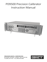
System Status Diagram
Figure 1 shows the System Status Diagram.
status.png
Figure 1. System Status Diagram

6270A, 8270A, 8370A
Programmers Reference Guide
4
List of Commands
Table 1 lists the command set for the Product in alphabetical order.
Table 1. List of Commands
Command Comment
*CLS Clear all status registers and the error
queue.
*ESE Set the Standard Event Status Enable
register.
*ESR? Query and clear the Standard Event
Status register.
*IDN? Query the instrument identification.
*OPC
Set the operation complete bit of the
Standard Event Enable Register when
all pending operations are completed.
*OPC? Return “1” when all pending operations
are completed.
*OPT? Returns information on currently fitted
options.
*RST Reset operating settings to default
states.
*SRE? Set the Service Request Enable
register.
*STB? Query the Status Byte Register.
*TST? Perform an instrument self-test and
return the results.
*WAI Force the command parser to wait until
all pending operations complete.

Pressure Controller/Calibrator
List of Commands
5
Table 1. List of Commands (cont.)
Command Comment
[SOURce]:PRESsure:CLIMit Control Limit
[SOURce]:PRESsure:SLEW Maximum slew rate
[SOURce]:PRESsure:SLIMit Static mode control limit
[SOURce]:PRESsure:STATic Static or Dynamic control
[SOURce]:PRESsure:TOLerance Control ready tolerance
[SOURce][:PRESsure]:TOLerance:RANGe Control tolerance is a percent of
range
[SOURce]:PRESsure[:LEVel][:IMMediate][:AMPLitude] Setpoint
CALCulate:ATMosphere Manual atmosphere value
CALCulate:ATMosphere:UNCertainty Manual atmosphere uncertainty
CALCulate:LIMit:LOWer Pressure low safety limit
CALCulate:LIMit:SLEW (for compatibility only)
CALCulate:LIMit:UPPer Pressure upper safety limit
CALCulate:LIMit:VENT Pressure vent limit
CALCulate:TARE:STATe Tare state
CALCulate:TARE:VALue Amount of tare
CALCulate: UNCertainty:CONTrol Additional control uncertainty
CALCulate: UNCertainty:PERCent Additional percent of reading
uncertainty
CALCulate: UNCertainty:PRESsure Additional pressure uncertainty
CALibration:MODE Calibration mode
CALibration[:PRESsure]:CALibration:POINts Number of expected adjustment
points
CALibration[:PRESsure]:CALibration:VALue Expected adjustment points
CALibration[:PRESsure]:DATA:POINts Number of calibration coefficients
CALibration[:PRESsure]:DATA:VALue Calibration coefficients
CALibration[:PRESsure]:DATE Last adjustment date
CALibration[:PRESsure]:SAVE Save new adjustment coefficients
CALibration[:PRESsure]:VALue Adjustment point
CALibration[:PRESsure]:ZERO:AUTO Autozero
CALibration[:PRESsure]:ZERO:BARometer Barometer selection
CALibration[:PRESsure]:ZERO:DATA Manual zeroing
CALibration[:PRESsure]:ZERO:INITiate Enter zeroing mode
CALibration[:PRESsure]:ZERO:MODule Zeroing module
CALibration[:PRESsure]:ZERO:MODule:NAME? Model number of zeroing module
CALibration[:PRESsure]:ZERO:MODule:SERial? Serial number of zeroing module
CALibration[:PRESsure]:ZERO:RUN Zero the instrument
CALibration[:PRESsure]:ZERO:STOP Abort zero

6270A, 8270A, 8370A
Programmers Reference Guide
6
Table 1. List of Commands (cont.)
Command Comment
DISPlay:BRIGhtness Display brightness
DISPlay:ENABle Display enable
DISPlay:LANGuage Display language
DISPlay:TEXT (for compatibility only)
EMM:MODE<1|2|3> MODE_DCV,MODE_DCI,MODE_SWI
TCH (8270A and 8370A)
EMM:MODE? MODE_DCV,MODE_DCI,MODE_SWI
TCH (8270A and 8370A)
EMM:VERSion? EMM firmware version
(8270A and 8370A)
EMM:SN? EMM serial number
(8270A and 8370A)
HART:POLL:STATe <0|1> Start/abort HART bus polling
(8270A and 8370A)
HART:POLL:STATe?
Returns 1 when bus polling is in
progress, return 2 when the bus polling
is completed, otherwise returns 0.
(8270A and 8370A)
HART:RESistor:STATe <0|1 > Enable/disable 250 HART resistor
(8270A and 8370A)
HART:RESistor:STATe? Returns 250 HART resistor setting
(8270A and 8370A)
HART:WRITe:STATe <0|1 > Enable/disable write function
(8270A and 8370A)
HART:WRITe:STATe? Returns 1 when write function is
enabled. (8270A and 8370A)
HART:UNIT:SYNC:STATe <0|1| >
Enable/disable pressure unit
synchronization between UUT and
mainframe. (8270A and 8370A)
HART:UNIT:SYNC:STATe? Returns state of pressure unit
synchronization (8270A and 8370A)
HART:CONNect:STATe? Returns 1 when link is active, otherwise
returns 0 (8270A and 8370A)
HART:DATA:PV? Return PV_VALUE
(8270A and 8370A)
HART:DATA:PV:UNIT <0 .. 255> Set PV_UNIT (8270A and 8370A)
HART:DATA:PV:UNIT? Returns code of PV_UNIT
(8270A and 8370A)
HART:DATA:SV? Returns SV_VALUE
(8270A and 8370A)

Pressure Controller/Calibrator
List of Commands
7
Table 1. List of Commands (cont.)
Command Comment
HART:DATA:SV:UNIT? Returns code of SV_UNIT
(8270A and 8370A)
HART:DATA:TV? Returns TV_VALUE (8270A and 8370A)
HART:DATA:TV:UNIT? Returns code of TV_UNIT
(8270A and 8370A)
HART:DATA:QV? Returns QV_VALUE (8270A and 8370A)
HART:DATA:QV:UNIT? Returns code of QV_UNIT
(8270A and 8370A)
HART:DATA:TAG <string> Set Tag (8270A and 8370A)
HART:DATA:TAG? Read Tag (8270A and 8370A)
HART:DATA:RANGe:UNIT? Read unit code of LRV and URV
(8270A and 8370A)
HART:DATA:RANGe:LOW <lrv> Set LRV (8270A and 8370A)
HART:DATA:RANGe:LOW? Read LRV (8270A and 8370A)
HART:DATA:RANGe:HIGH <urv> Set URV (8270A and 8370A)
HART:DATA:RANGe:HIGH? Read URV (8270A and 8370A)
HART:DATA:TL:UNIT? Read unit code of test limit
(8270A and 8370A)
HART:DATA:TL:LOW? Read LTL (8270A and 8370A)
HART:DATA:TL:HIGH? Read UTL (8270A and 8370A)
HART:TRIM:DAL:STATe <0|1 > Enable/disable 4 mA fixed current mode
(8270A and 8370A)
HART:TRIM:DAL:STATe? Read 4 mA fixed current mode
(8270A and 8370A)
HART:TRIM:DAL <measured milliamp> Trim 4 mA with real milliamp value
(8270A and 8370A)
HART:TRIM:DAH:STATe <0|1 > Enable/disable 20 mA fixed current mode
(8270A and 8370A)
HART:TRIM:DAH:STATe? Read 20 mA fixed current mode
(8270A and 8370A)
HART:TRIM:DAH <measured milliamp> Trim 20 mA with real milliamp value
(8270A and 8370A)
HART:TRIM:RANGe:LOW Set LRV with PV (8270A and 8370A)
HART:TRIM:RANGe:HIGH Set URV with PV (8270A and 8370A)
HART:TRIM:ZERO Set PV to zero (8270A and 8370A)
HART:DIAgnostic 1 Diagnostic the transmitter
(8270A and 8370A)

6270A, 8270A, 8370A
Programmers Reference Guide
8
Table 1. List of Commands (cont.)
Command Comment
HART:DATA:MESSage? Read the message
(8270A and 8370A)
HART:DATA:MESSage <string> Write the message
(8270A and 8370A)
HART:DATA:DESCiption? Read the description
(8270A and 8370A)
HART:DATA:DESCiption
<string>
Write the description (Only support
the hart version is 6.0 or greater
(8270A and 8370A)
HART:POLL:ADDRess? Read the poll address
(8270A and 8370A)
HART:POLL:ADDRess <value> Write the poll address (0~63)
(8270A and 8370A)
INSTrument:FUNCtion ?
Read system work mode
(8270A and 8370A)
INSTrument:FUNCtion<n> Write system work mode
(8270A and 8370A)
LOOP:STATe <0|1 > Enable/disable loop power
(8270A and 8370A)
LOOP:STATe? Read loop power status
(8270A and 8370A)
MEASure:ATMosphere
MEASure:VAL?
Triggers a new milliamp or voltage
measurement and return the reading
(8270A and 8370A)
DISPlay:VERSion? UI version
MEASure:SWITch Pressure switch input
MEASure:TEMPerature Temperature sensors
MEASure[:PRESsure] Pressure sensors
MEASure[:PRESsure]:SLEW Pressure slew rate
OUTPut:SOLenoid External solenoid drivers
OUTPut:CPS CPS option
OUTPut:ISOLation Isolation valve option
OUTPut:STATe Control mode
OUTPut:SOLenoid:PRESsure Operate external solenoid by pressure
reading
OUTPut:SOLenoid:STATe External solenoid drivers
OUTPut[:PRESsure]:MODE Control mode

Pressure Controller/Calibrator
List of Commands
9
Table 1. List of Commands (cont.)
Command Comment
SENSe:ATMosphere:MODule Atmospheric module
SENSe[:PRESsure]:FILTer Pressure reading filter
SENSe[:PRESsure]:MODE Absolute or Gauge
SENSe[:PRESsure]:MODule Module selection
SENSe[:PRESsure]:MODule:LOWer Module range low
SENSe[:PRESsure]:MODule:NAME Module model name
SENSe[:PRESsure]:MODule:SERial Module serial number
SENSe[:PRESsure]:MODule:UNCertainty:ADD Module uncertainty combination
SENSe[:PRESsure]:MODule:UNCertainty:RELative Module relative uncertainty
SENSe[:PRESsure]:MODule:UNCertainty:THReshold Module threshold uncertainty
SENSe[:PRESsure]:MODule:UNCertainty:ZERO Module zero uncertainty
SENSe[:PRESsure]:MODule:UPPer Module range upper
SENSe[:PRESsure]:MODule:VERSion Module version
SENSe[:PRESsure]:RANGe:LOWer Instrument range low
SENSe[:PRESsure]:RANGe:MODule Module range
SENSe[:PRESsure]:RANGe[:UPPer] Instrument range upper
SENSe[:PRESsure]:REFerence:MEDium Head height medium
SENSe[:PRESsure]:REFerence[:HEIGht] Head height
SENSe[:PRESsure]:REFerence[:HEIGht]:UNCertainty Head height uncertainty
SENSe[:PRESsure]:RESolution Resolution of pressure display
SENSe[:PRESsure]:RESolution:AUTO Auto-resolution
STATus:OPERation:CONDition Query the Operation Status Condition
Register
STATus:OPERation:ENABle Set the Operation Status Enable
Register
STATus:OPERation[:EVENt] Query and clear the Operation Status
Event Register
STATus:PRESet Set status enable registers to disabled
states
STATus:QUEStionable:CONDition Query the Questionable Status
Condition Register

6270A, 8270A, 8370A
Programmers Reference Guide
10
Table 1. List of Commands (cont.)
Command Comment
STATus:QUEStionable:ENABle Set the Questionable Status Enable
Register
STATus:QUEStionable[:EVENt] Query and clear the Questionable
Status Event Register
SYSTem:COMMunicate:GPIB[:SELF][:ADDRess] GPIB address
SYSTem:COMMunicate:SERial:CONTrol:RTS RS-232 RTS signal
SYSTem:COMMunicate:SERial:INTerface RS-232 interface type
SYSTem:COMMunicate:SERial[:RECeive]:BAUD RS-232 baud rate
SYSTem:COMMunicate:SERial[:RECeive]:BITS RS-232 data bits
SYSTem:COMMunicate:SERial[:RECeive]:EOL RS-232 end of line
SYSTem:COMMunicate:SERial[:RECeive]:PACE RS-232 handshake
SYSTem:COMMunicate:SERial[:RECeive]:PARity[:TYPE] RS-232 parity
SYSTem:COMMunicate:SERial[:RECeive]:SBITs RS-232 stop bits
SYSTem:COMMunicate:SERial[:TRANsmit]:BAUD RS-232 baud rate
SYSTem:COMMunicate:SERial[:TRANsmit]:BITS RS-232 data bits
SYSTem:COMMunicate:SERial[:TRANsmit]:EOL RS-232 end of line
SYSTem:COMMunicate:SERial[:TRANsmit]:PACE RS-232 handshake
SYSTem:COMMunicate:SERial[:TRANsmit]:PARity[:TYPE] RS-232 parity
SYSTem:COMMunicate:SERial[:TRANsmit]:SBITs RS-232 stop bits
SYSTem:COMMunicate:SOCKet:ADDRess Ethernet IP address
SYSTem:COMMunicate:SOCKet:DHCP Ethernet DHCP enable
SYSTem:COMMunicate:SOCKet:GATeway Ethernet Gateway address
SYSTem:COMMunicate:SOCKet:INTerface Ethernet interface type
SYSTem:COMMunicate:SOCKet:MAC Ethernet MAC address
SYSTem:COMMunicate:SOCKet:MASK Ethernet subnet mask
SYSTem:COMMunicate:SOCKet:NAME Ethernet system name
SYSTem:COMMunicate:SOCKet:PORT Ethernet Port number
SYSTem:COMMunicate:USB:EOL USB end of line
SYSTem:COMMunicate:USB:INTerface USB interface type
SYSTem:DATE Set the date of the system clock
SYSTem:DEFault Reset to system default

Pressure Controller/Calibrator
11
Table 1. List of Commands (cont.)
Command Comment
SYSTem:ERRor Read and remove the next error in
the error queue
SYSTem:KLOCk Keyboard lock
SYSTem:LANGuage Remote interface protocol emulation
SYSTem:PRESet Status Preset
SYSTem:STACk System stacking
SYSTem:TIME Set the time of the system clock
SYSTem:VERSion Query the SCPI version
TEST:ELECtronic Electronic self-test
TEST:PNEumatic Pneumatic self-test
TEST:STOP Abort self-test
TEST:TUNE Controller tune
UNIT:DEFine User-defined units
UNIT:LENGth Length units
UNIT:TEMPerature Temperature units
UNIT[:PRESsure] Pressure units

6270A, 8270A, 8370A
Programmers Reference Guide
12
Alphabetical List of Serial Commands
Each command description provides the structure (long and short format), a
description of the command purpose, a command example, an example of what
the command returns (as applicable to query commands), and notes specific to
the command. The bullet-points below apply to each group of commands:
Numeric data, specified by the mnemonic, <num>, uses ASCII characters to
represent numbers. Numbers may contain a plus or minus (‘+’ or ‘-’) sign,
decimal point (‘.’), and exponent (‘E’ or ‘e’) with its sign. If a fractional
component is received when only an integer is required, the number is
rounded to the nearest integer without any resulting error message.
Unrecognized commands or commands with incorrect syntax or invalid
parameters generate error messages in the error queue.
Upper case letters designate syntax that is required when issuing the
command. Lower case letters are optional and may be omitted.
< > indicates a required parameter.
[ ] indicates optional parameters.
( ) indicates a group of parameters that must be used together.
‘|’ indicates alternate parameter values.
<n> indicates a number is required.
<boolean> indicates a Boolean value (0 or 1) is required. The mnemonics
OFF and ON are also accepted for 0 and 1, respectively.
<unit> indicates max unit string is required (maximum 3 letters). The
character string must be enclosed in quotation marks.
<range> indicates a range value is required.
<name> indicates a character string is required. The character string must be
enclosed in quotation marks.
<year> indicates a four digit number is required.
<month> indicates a one or two digit number is required.
<day> indicates a one or two digit number is required.
<hour> indicates a one or two digit number is required.
<minute> indicates a one or two digit number is required.
<second> indicates a one or two digit number is required.
<psensor> indicates a pressure sensor index.
o 1 Active Pressure
o 3 System atmospheric pressure
o 4 Test pressure of control module
o 5 Pressure of module in slot 1
o 6 Supply pressure of control module
o 7 Exhaust pressure of control module
o 14 Test pressure of control module in Auxiliary chassis 1
o 15 Pressure of module in slot 2
o 16 Supply pressure of control module in Auxiliary chassis 1
o 17 Exhaust pressure of control module in Auxiliary chassis 1
o 24 Test pressure of control module in Auxiliary chassis 1

Pressure Controller/Calibrator
Alphabetical List of Serial Commands
13
o 25 Pressure of module in slot 3
o 26 Supply pressure of control module in Auxiliary chassis 2
o 27 Exhaust pressure of control module in Auxiliary chassis 2
o 35 Pressure of module in slot 4
o 45 Pressure of module in slot 5
o 55 Pressure of module in Auxiliary chassis 1, slot 1
o 65 Pressure of module in Auxiliary chassis 1, slot 2
o 75 Pressure of module in Auxiliary chassis 1, slot 3
o 85 Pressure of module in Auxiliary chassis 1, slot 4
o 95 Pressure of module in Auxiliary chassis 1, slot 5
o 105 Pressure of module in Auxiliary chassis 2, slot 1
o 115 Pressure of module in Auxiliary chassis 2, slot 2
o 125 Pressure of module in Auxiliary chassis 2, slot 3
o 135 Pressure of module in Auxiliary chassis 2, slot 4
o 145 Pressure of module in Auxiliary chassis 2, slot 5
<tsensor> indicates a temperature sensor number.
o 2 Sensor temperature of module in slot 1
o 12 Sensor Temperature of module in slot 2
o 22 Sensor Temperature of module in slot 3
o 32 Sensor Temperature of module in slot 4
o 42 Sensor Temperature of module in slot 5
o 52 Sensor temperature of module in Auxiliary chassis 1, slot 1
o 62 Sensor Temperature of module in Auxiliary chassis 1, slot 2
o 72 Sensor Temperature of module in Auxiliary chassis 1, slot 3
o 82 Sensor Temperature of module in Auxiliary chassis 1, slot 4
o 92 Sensor Temperature of module in Auxiliary chassis 1, slot 5
o 102 Sensor temperature of module in Auxiliary chassis 2, slot 1
o 112 Sensor Temperature of module in Auxiliary chassis 2, slot 2
o 122 Sensor Temperature of module in Auxiliary chassis 2, slot 3
o 132 Sensor Temperature of module in Auxiliary chassis 2, slot 4
o 142 Sensor Temperature of module in Auxiliary chassis 2, slot 5

6270A, 8270A, 8370A
Programmers Reference Guide
14
*CLS
Description: Clear the status registers and the error queue. Status event registers
are reset to 0. The registers affected are the Operation Status Event register,
Questionable Status Event register, and the Event Status Register. The
*CLS
command does not affect any of the associated condition or enable registers. It
may indirectly affect the Status Byte Register. The error queue is also cleared of
all logged errors.
Example: *CLS
Related Commands:
*ESR? SYSTem:ERRor?
STATus:OPERation:EVENt?
STATus:QUEStionable:EVENt?
*ESE <n>
*ESE?
Description: Set the Event Status Enable mask that determines which bits of the
Event Status Register are reported in the Event Status Summary bit (bit5) of the
Status Byte Register. <n> is the sum of the decimal values of the bits of
the Event
Status Register that will be reported in the Event Status Summary bit of the
Status Byte Register. The Status Byte register is updated to reflect any change in
the enable registers associated with the summary bits. Event Status Enable is set
to 0 at power-on.
*CLS
and
*RST
does not affect Event Status Enable.
Example: *ESE?
Response: 255
Set Example: *ESE 60
Related Commands:
*ESR?
*STB?
*ESR?
Description: Query the Event Status Register and clear the register. The Event
Status Register reports various instrument events or changes when they occur.
The return value is the sum of the decimal values of the asserted bits of the
register. The register bits, their decimal values (in parentheses), and their
definitions are as follows:
Bit 0 (1): Operation Complete
Bit 1 (2): [Not used]
Bit 2 (4): [Not used]
Bit 3 (8): Device Dependent Error
Bit 4 (16): Execution Error
Bit 5 (32): Command Error
Bit 6 (64): [Not used]
Bit 7 (128): Power On

Pressure Controller/Calibrator
Alphabetical List of Serial Commands
15
Bits in the Event Status Register may affect the Event Status Summary bit (bit 5)
of the Status Byte Register depending on the bits that are set in the Event Status
Enable register. *CLS and *RST does not affect Event Status Enable.
Example: *ESR?
Response: 32
Related Commands:
*ESE
*STB?
*CLS
*IDN?
Description: Query the product identification. The response contains the name of
the manufacturer, model number, serial number, firmware version. The product
information cannot be changed.
Example: *IDN?
Response: FLUKE,6270A,12345678,1.00
*OPC
Description: Set the Operation Complete bit of the Event Status Register when all
pending command operations complete. All commands are sequential, so the
Operation Complete bit is always set immediately when this command is
received.
Example: *OPC
Related Commands:
*ESR?
STATus:OPERation:EVENt?
*OPC
*WAI
*OPC?
Description: Return “1” when all pending command operations are complete. All
commands are sequential, so this query always returns ‘1’ immediately.
Example: *OPC?
Response: 1
Related Commands:
*OPC
STATus:OPERation[:EVENt]?

6270A, 8270A, 8370A
Programmers Reference Guide
16
*OPT?
Description: Query the instrument options. Currently this instrument has no
options to report.
Example: *OPT?
Response: 0
Related Commands:
*IDN?
*RST
Description: Sets channel instrument settings to default states. The reset
command performs the following actions:
Stop all running tasks and tests
Stop controller and enter Measure mode if not already in Vent mode
Settings and memory not affected by
*RST
include data file memory, setup file
memory, language, remote interface settings, time and date, password
configuration, and instrument calibration. Reset also does not directly affect status
registers or the error queue, nor does it affect status enable registers.
Example: *RST
Related Commands:
*CLS
*SRE <n>
*SRE?
Description: Set the Service Request Enable for the Status Byte register. The
Service Request Enable determines which bits of the Status Byte register are
reported in the Master Summary Status bit of the Status Byte register. <n> is the
sum of the decimal values of the bits of the Status Byte register that will be
reported in the Master Status Summary bit.
The Status Byte register is updated to reflect any change in the enable registers
associated with the summary bits. Service Request Enable is set to 0 at power-
on.*CLS and
*RST
does not affect Event Status Enable.
Example: *SRE?
Response: 32
Set Example: *SRE 32
Related Commands:
*STB?
/