CAME PROXINET Installation guide
- Category
- Security access control systems
- Type
- Installation guide

FB00378-EN
BURGLAR ALARM
CONTROL UNIT
TECHNICAL MANUAL
PROXINETW2

Page 2 - Manual code: FB00378-EN ver. 1 05/2016 © CAME S.p.A. - The data and information provided in this manual are subject to change at any time without prior notice.
ENGLISH
INDICE
SYMBOLS AND GLOSSARY. . . . . . . . . . . . . . . . . . .PAG. 3
INSTALLER MENU . . . . . . . . . . . . . . . . . . . . . . . PAG. 4
PRELIMINARY INFORMATION . . . . . . . . . . . . . . . . . . . . . . 4
Accessing the installer menu . . . . . . . . . . . . . . . . . . . . . . . . . . 4
SYSTEM. . . . . . . . . . . . . . . . . . . . . . . . . . . . . . . . . 4
Managed areas . . . . . . . . . . . . . . . . . . . . . . . . . . . . . . . . . 4
Keypads. . . . . . . . . . . . . . . . . . . . . . . . . . . . . . . . . . . . .4
Readers. . . . . . . . . . . . . . . . . . . . . . . . . . . . . . . . . . . . .4
Radio modules . . . . . . . . . . . . . . . . . . . . . . . . . . . . . . . . . 5
Radio sirens. . . . . . . . . . . . . . . . . . . . . . . . . . . . . . . . . . .5
Touchscreen . . . . . . . . . . . . . . . . . . . . . . . . . . . . . . . . . . 5
Keypad self-learning . . . . . . . . . . . . . . . . . . . . . . . . . . . . . . 5
Reader self-learning . . . . . . . . . . . . . . . . . . . . . . . . . . . . . . 5
Input test . . . . . . . . . . . . . . . . . . . . . . . . . . . . . . . . . . . . 5
Control unit tamper test . . . . . . . . . . . . . . . . . . . . . . . . . . . . .5
Control unit battery test . . . . . . . . . . . . . . . . . . . . . . . . . . . . .5
Siren test . . . . . . . . . . . . . . . . . . . . . . . . . . . . . . . . . . . . 5
Output test . . . . . . . . . . . . . . . . . . . . . . . . . . . . . . . . . . . 5
Change RS485 bus speed. . . . . . . . . . . . . . . . . . . . . . . . . . . .6
PXLAN/PXWEB DHCP activation . . . . . . . . . . . . . . . . . . . . . . . . .6
Selecting the keypad to emulate . . . . . . . . . . . . . . . . . . . . . . . . 6
Setting the IP ADDRESS . . . . . . . . . . . . . . . . . . . . . . . . . . . . 6
Setting the NETMASK . . . . . . . . . . . . . . . . . . . . . . . . . . . . . .6
Setting the GATEWAY: . . . . . . . . . . . . . . . . . . . . . . . . . . . . . .6
Setting the COMPUTER IP PORT. . . . . . . . . . . . . . . . . . . . . . . . .6
Setting the touchscreen IP PORT . . . . . . . . . . . . . . . . . . . . . . . . 6
SCENARIOS . . . . . . . . . . . . . . . . . . . . . . . . . . . . . . . 7
Action on areas . . . . . . . . . . . . . . . . . . . . . . . . . . . . . . . . .7
Associated areas . . . . . . . . . . . . . . . . . . . . . . . . . . . . . . . . 7
Output action . . . . . . . . . . . . . . . . . . . . . . . . . . . . . . . . . . 7
Associated outputs . . . . . . . . . . . . . . . . . . . . . . . . . . . . . . . 7
Scenario description . . . . . . . . . . . . . . . . . . . . . . . . . . . . . . 7
Voice recording . . . . . . . . . . . . . . . . . . . . . . . . . . . . . . . . . 7
AREAS . . . . . . . . . . . . . . . . . . . . . . . . . . . . . . . . . 8
Forcing an area . . . . . . . . . . . . . . . . . . . . . . . . . . . . . . . . . 8
Slave status. . . . . . . . . . . . . . . . . . . . . . . . . . . . . . . . . . .8
Area description. . . . . . . . . . . . . . . . . . . . . . . . . . . . . . . . .8
Voice recording . . . . . . . . . . . . . . . . . . . . . . . . . . . . . . . . . 8
Pre-alarm time . . . . . . . . . . . . . . . . . . . . . . . . . . . . . . . . .8
Pre-alarm COUNTER . . . . . . . . . . . . . . . . . . . . . . . . . . . . . . 8
KEYPADS . . . . . . . . . . . . . . . . . . . . . . . . . . . . . . . . 9
Changing the keypad . . . . . . . . . . . . . . . . . . . . . . . . . . . . . . 9
Associated areas . . . . . . . . . . . . . . . . . . . . . . . . . . . . . . . . 9
Scenarios . . . . . . . . . . . . . . . . . . . . . . . . . . . . . . . . . . . .9
Tamper . . . . . . . . . . . . . . . . . . . . . . . . . . . . . . . . . . . . . 9
Entry buzzer . . . . . . . . . . . . . . . . . . . . . . . . . . . . . . . . . . 9
Exit buzzer . . . . . . . . . . . . . . . . . . . . . . . . . . . . . . . . . . . 9
Alarm buzzer . . . . . . . . . . . . . . . . . . . . . . . . . . . . . . . . . . 9
GONG buzzer . . . . . . . . . . . . . . . . . . . . . . . . . . . . . . . . . . 9
Keypad masking . . . . . . . . . . . . . . . . . . . . . . . . . . . . . . . . 9
Supervision . . . . . . . . . . . . . . . . . . . . . . . . . . . . . . . . . . . 9
Keypad description . . . . . . . . . . . . . . . . . . . . . . . . . . . . . . . 9
RADIO MODULES . . . . . . . . . . . . . . . . . . . . . . . . . . . .10
Module description . . . . . . . . . . . . . . . . . . . . . . . . . . . . . . 10
Jamming . . . . . . . . . . . . . . . . . . . . . . . . . . . . . . . . . . . 10
READERS . . . . . . . . . . . . . . . . . . . . . . . . . . . . . . . .10
Associated areas . . . . . . . . . . . . . . . . . . . . . . . . . . . . . . . 10
Scenarios . . . . . . . . . . . . . . . . . . . . . . . . . . . . . . . . . . . 10
Tamper . . . . . . . . . . . . . . . . . . . . . . . . . . . . . . . . . . . . 10
Entry buzzer . . . . . . . . . . . . . . . . . . . . . . . . . . . . . . . . . 10
Exit buzzer . . . . . . . . . . . . . . . . . . . . . . . . . . . . . . . . . . 10
Alarm buzzer . . . . . . . . . . . . . . . . . . . . . . . . . . . . . . . . . 10
Reader description . . . . . . . . . . . . . . . . . . . . . . . . . . . . . . 10
INPUTS . . . . . . . . . . . . . . . . . . . . . . . . . . . . . . . . .10
Status. . . . . . . . . . . . . . . . . . . . . . . . . . . . . . . . . . . . . 11
Type . . . . . . . . . . . . . . . . . . . . . . . . . . . . . . . . . . . . . 11
Switching a delayed input to immediate . . . . . . . . . . . . . . . . . . . 12
Balancing . . . . . . . . . . . . . . . . . . . . . . . . . . . . . . . . . . . 12
Radio channel. . . . . . . . . . . . . . . . . . . . . . . . . . . . . . . . . 12
Radio device learning . . . . . . . . . . . . . . . . . . . . . . . . . . . . . 12
Radio supervision . . . . . . . . . . . . . . . . . . . . . . . . . . . . . . . 12
VIDEO VERIFICATION . . . . . . . . . . . . . . . . . . . . . . . . . . . . . 12
photo format . . . . . . . . . . . . . . . . . . . . . . . . . . . . . . . . . 12
interframe. . . . . . . . . . . . . . . . . . . . . . . . . . . . . . . . . . . 12
frame number . . . . . . . . . . . . . . . . . . . . . . . . . . . . . . . . 12
video duration. . . . . . . . . . . . . . . . . . . . . . . . . . . . . . . . . 12
acquisition . . . . . . . . . . . . . . . . . . . . . . . . . . . . . . . . . . 12
Number of pulses . . . . . . . . . . . . . . . . . . . . . . . . . . . . . . . 13
Pulse interval . . . . . . . . . . . . . . . . . . . . . . . . . . . . . . . . . 13
Associated areas . . . . . . . . . . . . . . . . . . . . . . . . . . . . . . . 13
And/or areas . . . . . . . . . . . . . . . . . . . . . . . . . . . . . . . . . 13
AND input . . . . . . . . . . . . . . . . . . . . . . . . . . . . . . . . . . 13
Automatic rearming . . . . . . . . . . . . . . . . . . . . . . . . . . . . . . 13
Excluding an input . . . . . . . . . . . . . . . . . . . . . . . . . . . . . . 13
Self-exclusion. . . . . . . . . . . . . . . . . . . . . . . . . . . . . . . . . 13
Gong output. . . . . . . . . . . . . . . . . . . . . . . . . . . . . . . . . . 13
Associating an output . . . . . . . . . . . . . . . . . . . . . . . . . . . . . 13
Commanding an output . . . . . . . . . . . . . . . . . . . . . . . . . . . . 13
Arming action . . . . . . . . . . . . . . . . . . . . . . . . . . . . . . . . . 14
Input description . . . . . . . . . . . . . . . . . . . . . . . . . . . . . . . 14
Voice recording . . . . . . . . . . . . . . . . . . . . . . . . . . . . . . . . 14
OUTPUTS . . . . . . . . . . . . . . . . . . . . . . . . . . . . . . . .14
Status. . . . . . . . . . . . . . . . . . . . . . . . . . . . . . . . . . . . . 14
Duration of activation . . . . . . . . . . . . . . . . . . . . . . . . . . . . . 14
Activation delay . . . . . . . . . . . . . . . . . . . . . . . . . . . . . . . . 14
Deactivation delay . . . . . . . . . . . . . . . . . . . . . . . . . . . . . . 15
Security. . . . . . . . . . . . . . . . . . . . . . . . . . . . . . . . . . . . 15
Remote activation. . . . . . . . . . . . . . . . . . . . . . . . . . . . . . . 15
Storing an event . . . . . . . . . . . . . . . . . . . . . . . . . . . . . . . 15
Slave output . . . . . . . . . . . . . . . . . . . . . . . . . . . . . . . . . 15
OUTPUT description. . . . . . . . . . . . . . . . . . . . . . . . . . . . . . 15
Voice recording . . . . . . . . . . . . . . . . . . . . . . . . . 15
TIMES. . . . . . . . . . . . . . . . . . . . . . . . . . . . . . . . . .15
Self-testing interval . . . . . . . . . . . . . . . . . . . . . . . . . . . . . . 15
RADIO supervision time . . . . . . . . . . . . . . . . . . . . . . . . . . . . 15
Battery test interval . . . . . . . . . . . . . . . . . . . . . . . . . . . . . . 16
Mains failure alert delay. . . . . . . . . . . . . . . . . . . . . . . . . . . . 16
General alarm time . . . . . . . . . . . . . . . . . . . . . . . . . . . . . . 16
Sabotage time . . . . . . . . . . . . . . . . . . . . . . . . . . . . . . . . 16
Technical alarm time . . . . . . . . . . . . . . . . . . . . . . . . . . . . . 16
Burglary alarm time . . . . . . . . . . . . . . . . . . . . . . . . . . . . . . 16
Gong output time . . . . . . . . . . . . . . . . . . . . . . . . . . . . . . . 16
Exit time . . . . . . . . . . . . . . . . . . . . . . . . . . . . . . . . . . . 16
Entry time 1 and 2 . . . . . . . . . . . . . . . . . . . . . . . . . . . . . . 16
Patrol time . . . . . . . . . . . . . . . . . . . . . . . . . . . . . . . . . . 16
TELEPHONE ALERTS . . . . . . . . . . . . . . . . . . . . . . . . . .17
System alarm . . . . . . . . . . . . . . . . . . . . . . . . . . . . . . . . . 17
Individual area alarm . . . . . . . . . . . . . . . . . . . . . . . . . . . . . 17
System sabotage alarm . . . . . . . . . . . . . . . . . . . . . . . . . . . . 17
Control unit and bus peripheral device sabotage alarm . . . . . . . . . . . . 17
Individual area sabotage alarm . . . . . . . . . . . . . . . . . . . . . . . . 17
Input sabotage alarm . . . . . . . . . . . . . . . . . . . . . . . . . . . . . 17
System technical alarm . . . . . . . . . . . . . . . . . . . . . . . . . . . . 17
Individual area technical alarm . . . . . . . . . . . . . . . . . . . . . . . . 18
System burglary alarm . . . . . . . . . . . . . . . . . . . . . . . . . . . . 18
Individual area burglary alarm. . . . . . . . . . . . . . . . . . . . . . . . . 18
Arming the system . . . . . . . . . . . . . . . . . . . . . . . . . . . . . . 18
Disarming the system. . . . . . . . . . . . . . . . . . . . . . . . . . . . . 18
Partially arming the system . . . . . . . . . . . . . . . . . . . . . . . . . . 18
Arming and disarming individual areas . . . . . . . . . . . . . . . . . . . . 18
System fault . . . . . . . . . . . . . . . . . . . . . . . . . . . . . . . . . 18
Battery fault. . . . . . . . . . . . . . . . . . . . . . . . . . . . . . . . . . 18
230 V power failure . . . . . . . . . . . . . . . . . . . . . . . . . . . . . . 18
Power supply fault . . . . . . . . . . . . . . . . . . . . . . . . . . . . . . 19
Fuse failure . . . . . . . . . . . . . . . . . . . . . . . . . . . . . . . . . . 19
PSTN and GSM fault. . . . . . . . . . . . . . . . . . . . . . . . . . . . . . 19
Entering the code . . . . . . . . . . . . . . . . . . . . . . . . . . . . . . . 19
Reading the key. . . . . . . . . . . . . . . . . . . . . . . . . . . . . . . . 19
Input alarm . . . . . . . . . . . . . . . . . . . . . . . . . . . . . . . . . . 19
Other . . . . . . . . . . . . . . . . . . . . . . . . . . . . . . . . . . . . . 19
ASSOCIATING OUTPUTS . . . . . . . . . . . . . . . . . . . . . . . . .19
General area alarm output . . . . . . . . . . . . . . . . . . . . . . . . . . 19
Area sabotage alarm output. . . . . . . . . . . . . . . . . . . . . . . . . . 20
Technical area alarm output. . . . . . . . . . . . . . . . . . . . . . . . . . 20
Burglary area alarm output . . . . . . . . . . . . . . . . . . . . . . . . . . 20
Area ready output . . . . . . . . . . . . . . . . . . . . . . . . . . . . . . . 20

Page 3 - Manual code: FB00378-EN ver. 1 05/2016 © CAME S.p.A. - The data and information provided in this manual are subject to change at any time without prior notice.
ENGLISH
Symbols and glossary
This symbol indicates parts about safety.
This symbol indicates parts to read carefully.
Light signal on and steady.
Light signal off.
Light signal flashing.
INSTALLER: the person/company responsible for the design, con-
struction and programming of the burglar alarm system.
USER: the person(s) using the burglar alarm system.
General area alarm output . . . . . . . . . . . . . . . . . . . . . . . . . . 20
Area buzzer output . . . . . . . . . . . . . . . . . . . . . . . . . . . . . . 20
Area TC output . . . . . . . . . . . . . . . . . . . . . . . . . . . . . . . . 20
System fault output . . . . . . . . . . . . . . . . . . . . . . . . . . . . . . 20
Battery fault output . . . . . . . . . . . . . . . . . . . . . . . . . . . . . . 20
Mains fault output. . . . . . . . . . . . . . . . . . . . . . . . . . . . . . . 20
Partially armed area output . . . . . . . . . . . . . . . . . . . . . . . . . . 20
CODES . . . . . . . . . . . . . . . . . . . . . . . . . . . . . . . . .20
Changing the technical code . . . . . . . . . . . . . . . . . . . . . . . . . 20
Accessing the technical menu. . . . . . . . . . . . . . . . . . . . . . . . . 21
Enabling control unit programming from a PC. . . . . . . . . . . . . . . . . 21
Enabling a code . . . . . . . . . . . . . . . . . . . . . . . . . . . . . . . . 21
Areas associated with the code . . . . . . . . . . . . . . . . . . . . . . . . 21
User code authorisation . . . . . . . . . . . . . . . . . . . . . . . . . . . . 21
Enabling remote control. . . . . . . . . . . . . . . . . . . . . . . . . . . . 21
User code visibility . . . . . . . . . . . . . . . . . . . . . . . . . . . . . . 21
Associating an output . . . . . . . . . . . . . . . . . . . . . . . . . . . . . 21
Code group . . . . . . . . . . . . . . . . . . . . . . . . . . . . . . . . . . 21
Enabling the user menu. . . . . . . . . . . . . . . . . . . . . . . . . . . . 21
Enabling the arming user menu . . . . . . . . . . . . . . . . . . . . . . . 21
Enabling the event user menu. . . . . . . . . . . . . . . . . . . . . . . . . 21
Enabling the postponement user menu . . . . . . . . . . . . . . . . . . . . 22
Enabling the telephony user menu . . . . . . . . . . . . . . . . . . . . . . 22
Enabling the code user menu . . . . . . . . . . . . . . . . . . . . . . . . . 22
Enabling the code management user menu . . . . . . . . . . . . . . . . . . 22
Enabling the key management user menu . . . . . . . . . . . . . . . . . . 22
User description. . . . . . . . . . . . . . . . . . . . . . . . . . . . . . . . 22
Changing the user code. . . . . . . . . . . . . . . . . . . . . . . . . . . . 22
Voice recording . . . . . . . . . . . . . . . . . . . . . . . . . . . . . . . . 22
KEYS . . . . . . . . . . . . . . . . . . . . . . . . . . . . . . . . . .22
Checking the key . . . . . . . . . . . . . . . . . . . . . . . . .22
Enabling the key . . . . . . . . . . . . . . . . . . . . . . . . . 22
Areas associated with the key. . . . . . . . . . . . . . . . . . . . . . . . . 22
Key learning. . . . . . . . . . . . . . . . . . . . . . . . . . . . . . . . . . 22
Key authorisation . . . . . . . . . . . . . . . . . . . . . . . . . . . . . . . 23
Associating an output . . . . . . . . . . . . . . . . . . . . . . . . . . . . . 23
Group . . . . . . . . . . . . . . . . . . . . . . . . . . . . . . . . . . . . . 23
Key description . . . . . . . . . . . . . . . . . . . . . . . . . . . . . . . . 23
Voice recording . . . . . . . . . . . . . . . . . . . . . . . . . 23
TRANSMITTERS . . . . . . . . . . . . . . . . . . . . . . . . . . . .23
Enabling a transmitter. . . . . . . . . . . . . . . . . . . . . . . . . . . . . 23
Areas associated with the transmitter . . . . . . . . . . . . . . . . . . . . . 23
Learning transmitters . . . . . . . . . . . . . . . . . . . . . . . . . . . . . 23
Scenarios . . . . . . . . . . . . . . . . . . . . . . . . . . . . . . . . . . . 23
Transmitter description . . . . . . . . . . . . . . . . . . . . . . . . . . . . 23
TELEPHONES . . . . . . . . . . . . . . . . . . . . . . . . . . . . . .24
Telephone number . . . . . . . . . . . . . . . . . . . . . . . . . . . . . . 24
Telephone communication format. . . . . . . . . . . . . . . . . . . . . . . 24
System coding . . . . . . . . . . . . . . . . . . . . . . . . . . . . . . . . 24
Call attempts . . . . . . . . . . . . . . . . . . . . . . . . . . . . . . . . . 24
Common message . . . . . . . . . . . . . . . . . . . . . . . . . . . . . . 24
Telephone description. . . . . . . . . . . . . . . . . . . . . . . . . . . . . 24
Voice recording . . . . . . . . . . . . . . . . . . . . . . . . . . . . . . . . 24
TELEPHONE OPTIONS . . . . . . . . . . . . . . . . . . . . . . . . .25
Call sequence. . . . . . . . . . . . . . . . . . . . . . . . . . . . . . . . . 25
Stopping a call sequence using a telephone. . . . . . . . . . . . . . . . . . 25
Stopping a call sequence using a code . . . . . . . . . . . . . . . . . . . . 25
Phone call priority. . . . . . . . . . . . . . . . . . . . . . . . . . . . . . . 25
Enabling remote control via SMS . . . . . . . . . . . . . . . . . . . . . . . 25
Enabling remote control via PSTN . . . . . . . . . . . . . . . . . . . . . . . 25
Enabling remote installer service via PSTN . . . . . . . . . . . . . . . . . . 25
Enabling remote control via GSM . . . . . . . . . . . . . . . . . . . . . . . 25
Safe GSM . . . . . . . . . . . . . . . . . . . . . . . . . . . . . . . . . . . 25
Telephones enabled for safe GSM . . . . . . . . . . . . . . . . . . . . . . . 25
SKIPPING THE ANSWERING SERVICE . . . . . . . . . . . . . . . . . . . . . 25
Rings from PSTN . . . . . . . . . . . . . . . . . . . . . . . . . . . . . . . 26
Enabling PSTN line control . . . . . . . . . . . . . . . . . . . . . . . . . . 26
Enabling GSM line control. . . . . . . . . . . . . . . . . . . . . . . . . . . 26
Call delay . . . . . . . . . . . . . . . . . . . . . . . . . . . . . . . . . . . 26
Displaying the GSM field . . . . . . . . . . . . . . . . . . . . . . . . . . . 26
SPECIAL FEATURES . . . . . . . . . . . . . . . . . . . . . . . . . . .26
Keypad display . . . . . . . . . . . . . . . . . . . . . . . . . . . . . . . . 26
Displaying open inputs . . . . . . . . . . . . . . . . . . . . . . . . . . . . 26
Printer output enabled . . . . . . . . . . . . . . . . . . . . . . . . . . . . 26
Arming the control unit after power-on . . . . . . . . . . . . . . . . . . . . 26
Quick arming . . . . . . . . . . . . . . . . . . . . . . . . . . . . . . . . . 26
Masking the control unit status . . . . . . . . . . . . . . . . . . . . . . . . 27
Pre-arming test . . . . . . . . . . . . . . . . . . . . . . . . . . . . . . . . 27
Supervision repetition . . . . . . . . . . . . . . . . . . . . . . . . . . . . . 27
Installer description . . . . . . . . . . . . . . . . . . . . . . . . . . . . . . 27
PROGRAMMER . . . . . . . . . . . . . . . . . . . . . . . . . . . . .27
Hours . . . . . . . . . . . . . . . . . . . . . . . . . . . . . . . . . . . . . 27
Minutes . . . . . . . . . . . . . . . . . . . . . . . . . . . . . . . . . . . 27
Action . . . . . . . . . . . . . . . . . . . . . . . . . . . . . . . . . . . . 27
Address . . . . . . . . . . . . . . . . . . . . . . . . . . . . . . . . . . . . 27
Status. . . . . . . . . . . . . . . . . . . . . . . . . . . . . . . . . . . . . 28
Postponement. . . . . . . . . . . . . . . . . . . . . . . . . . . . . . . . . 28
EVENTS . . . . . . . . . . . . . . . . . . . . . . . . . . . . . . . . .28
Events menu . . . . . . . . . . . . . . . . . . . . . . . . . . . . . . . . . 28
Event printing . . . . . . . . . . . . . . . . . . . . . . . . . . . . . . . . 28
CLOCK . . . . . . . . . . . . . . . . . . . . . . . . . . . . . . . . .28
DEFAULT PARAMETERS . . . . . . . . . . . . . . . . . . . . . . . . .28
CONTROL UNIT INFO . . . . . . . . . . . . . . . . . . . . . . . . . .28
RECORDING AUDIO MESSAGES . . . . . . . . . . . . . . . . . . . . .29
RADIO SIRENS . . . . . . . . . . . . . . . . . . . . . . . . . . . . .29
Associated areas . . . . . . . . . . . . . . . . . . . . . . . . . . . . . . . 29
Radio siren learning. . . . . . . . . . . . . . . . . . . . . . . . . . . . . . 29
radio supervision . . . . . . . . . . . . . . . . . . . . . . . . . . . . . . . 29
Exit time alert . . . . . . . . . . . . . . . . . . . . . . . . . . . . . . . . . 29
System armed alert . . . . . . . . . . . . . . . . . . . . . . . . . . . . . . 29
Areas o alert. . . . . . . . . . . . . . . . . . . . . . . . . . . . . . . . . 29
Radio siren description . . . . . . . . . . . . . . . . . . . . . . . . . . . . 29
EVENT MESSAGES . . . . . . . . . . . . . . . . . . . . . . . PAG. 30

Page 4 - Manual code: FB00378-EN ver. 1 05/2016 © CAME S.p.A. - The data and information provided in this manual are subject to change at any time without prior notice.
ENGLISH
Installer Menu
Preliminary information
ACCESSING THE INSTALLER MENU
In order to start up the system and program it using the keypad,
you need to access the Installer Menu (hereinafter referred to as
the Technical Menu).
Depending on the TECH MENU ACCESS (CODES -> INSTALLER TECHNICAL CODE)
parameter, access to the Technical Menu may or may not be
preceded by the User Code.
The parameter can only be changed via PC with the PXManager
software.
Simultaneous access to the technical or user menu from
multiple keypads is not allowed. The Technical Code can be
changed later on.
DIRECT ACCESS
(A)
08:23 16/05/10
ENTER CODE
MENU SELECTION
(222222)
To access the Technical Menu directly, the system must be turned
off. Enter the Technical Code and then press (A). If the code is fewer
than 6 digits, confirm code entry by pressing (*).
ACCESS PRECEDED BY USER CODE
(A) (B)
08:23 16/05/10
ENTER CODE
WAITING FOR COMMAND
*=USER MENU
MENU SELECTION SELF-LEARNING
(123456)
(222222)
To access the Technical Menu, enter the User Code followed by the
Technical Code and finally press (A). Press (B) to enter self-learning
mode. It is only possible to choose between these two menus from
the control unit and not from the remote keypad.
If the codes are fewer than 6 digits, confirm code entry by pressing
(*).
N.B. IN ALL SUBSEQUENT INSTRUCTIONS, THIS OPERATION
WILL ALWAYS BE CALLED
“ENTER THE TECHNICAL MENU”
WITH NO OTHER DETAILS.
This manual shows all the menu headings. Those only avail-
able from PXManager will be marked by the icon.
System
The system menu is used to define the system components (areas,
keypads, readers etc.), address them and perform a series of tests.
The system configuration procedure is as follows:
Enter the Technical Menu, then...
(▲)/(▼) SYSTEM 02 (*); use (▲)/(▼) to choose the change to the system
to be configured...
MODIFY SYSTEM
KEYPADS ADDRESSING
READERS ADDRESSING
TEST SYSTEM
RS485 BUS
PXLAN/PXWEB CONFIGURATION
and press (*).
Then use (▲)/(▼) to go through the options.
The value selection is indicated in the illustrations on the display,
which always shows the default configuration. Press (#) to exit at
any time.
MANAGED AREAS
MANAGED AREAS
###----- (1)/(8)
The system is considered fully armed is all the selected areas are
armed.
Use the number keys (1)...(8) to select the areas to manage.
KEYPADS
KEYPADS
-- (2)/(3)
To enable/disable any keypads connected on the bus (maximum 2).
Use the number keys (2)...(3) (keypad 1 is the local control unit one
and cannot be enabled/disabled) to select the keypads to manage.
Example: if we enter 3, the display shows -#. The
system will include keypad 1 on the control unit (not
shown) and keypad 3 on the bus.
READERS
READERS
-- (1)/(2)
To enable/disable any readers connected on the bus (maximum 2).
Use the number keys (1) and (2) to select the readers to manage.
Example: if we enter 1, the display shows #-.

Page 5 - Manual code: FB00378-EN ver. 1 05/2016 © CAME S.p.A. - The data and information provided in this manual are subject to change at any time without prior notice.
ENGLISH
RADIO MODULES
RADIO MODULES
-- (2)/(3)
To enable/disable any radio expansion modules connected on the
bus (maximum 2).
Use the number keys (2)...(3) (module 1 is the local control unit one
and cannot be enabled/disabled) to select the radio modules to
manage.
Example: if we enter 2, the display shows #-. The sys-
tem will include radio module 1 on the control unit (not
shown) and radio module 2 on the bus.
RADIO SIRENS
RADIO SIRENS
-- (2)/(4)
To enable/disable any radio sirens that can be connected (maxi-
mum 4).
Use the number keys (2)...(4) (siren 1 is the first radio siren connect-
ed) to select the radio sirens to manage.
TOUCHSCREEN
TOUCH SCREEN
YES (+)/(-)
To enable/disable the connection to the Master Touchscreen (to
manage the burglar alarm control unit in a home automation sys-
tem).
KEYPAD SELF-LEARNING
ON KEYPAD XX
PRESS * AND #
KEYPAD XX OK
The control unit tests the remote keypads and, if no changes are
detected, the local display shows KEYPADS SELF-LEARNT. The remote
display shows KEYPAD XX OK.
Otherwise, it will show the keypads that have been configured but
not yet addressed, showing ON KEYPAD XX, PRESS * AND #
Go to the remote keypad shown and press (*) and (#) together until
the keypad goes off, then release then and turn it back on again: af-
ter about 10 seconds, the control unit display shows KEYPAD XX OK.
Before starting the self-learning procedure, set the address
of the keypads to be configured to 16:
• for keypads with FW >= 1.05 KEYPAD LOCAL MENU,
• for keypads with FW< 1.05 press (*) (#) (5) at the same time.
The default address of all the remote keypads is 1. Starting directly
from the remote keypad menu, you can change the address:
Hold down (*); use (▲)/(▼) to select the ADDRESS menu and (+)/(-) to
choose the desired address.
Perform the operation on all the remote keypads present.
The keypad address change menu can be changed within 4
minutes from the first time the device is booted.
READER SELF-LEARNING
ON READER XX
APPROACH THE KEY
READER OK
PRESS */OK
If the readers are not configured on the keypad, the message
shown is PLACE KEY ON READER XX
Go to the remote reader indicated and move a transponder key up
close until the reader emits a confirmation
beep
. The control unit
display will show the message READER XX OK.
After a few seconds, addressing will automatically begin for the 2nd
reader (if neccesary), otherwise press (#) to exit. The system will
display them in a cycle, emitting a beep for each one.
INPUT TEST
INPUT TEST
*=START TEST (*)
AREAS TO TEST
### (1)...(3)
The test for open inputs can be carried out on the system as a
whole or only certain selected areas only.
Once (*) has been pressed to start the input test, before displaying
the choice of the areas to test, the keypad will display the message
WAITING FOR SYNCHRONIZATION for a few seconds in order to allow the
various devices connected to the control unit to align themselves
with the baud rate.
Use the number keys (1)...(3) to enable/disable the areas.
Example: if we enter 2, the display shows #-#. The test
will only be carried out in areas 1 and 3.
CONTROL UNIT TAMPER TEST
This allows you to check the control unit tamper status.
C.U. TAMP. TEST
*=START TEST (*)
CONTROL UNIT BATTERY TEST
This allows you to perform an immediate check on the control unit
battery status.
C.U. BATT. TEST
*=START TEST (*)
SIREN TEST
The test allows you to manually control the control unit alarm relay
output.
SIREN TEST
*=START TEST (*)
OUTPUT TEST
OUTPUT TEST
*=START TEST (*)
The test allows you to manually control the system outputs.

Page 6 - Manual code: FB00378-EN ver. 1 05/2016 © CAME S.p.A. - The data and information provided in this manual are subject to change at any time without prior notice.
ENGLISH
CHANGE RS485 BUS SPEED
BAUD RATE RS485
115200 (+)/(-)
This allows you to change the communication speed with the vari-
ous devices connected to the bus on the control unit.
The possible choices are:
• 115200 baud (default)
• 38400 baud
• 9600 baud
• 4800 baud
• 2400 baud
The devices automatically adapt to the speed of the control
unit in no longer than 30 seconds. To enable this, and make sure
that the control unit does not generate a tampering alarm, when
switching on, on exiting the technical manual and at the end of
PC programming, the keypad will display WAITING FOR SYNCHRONIZATION.
The automatic adjustment of the communication speed be-
tween the control unit and the peripheral devices is only available
from a certain FW version. For all devices with FW lower than the
one indicated, the baud to be set on the control unit is 115200.
DEVICE COMPATIBILITY
PXKD
keypad
FW version ≥1.06 (can be identified on the
keypad menu and on the board label)
PXWKTB - PXWKTN
keypad
FW version ≥1.09 (can be identified on the
keypad menu and on the board label)
PXITU
transponder reader
FW version ≥1.04 (can be identified on the
board label)
PXWRX
radio receiver
FW version ≥1.04 (can be identified on the
board label)
PXLAN/PXWEB DHCP ACTIVATION
PXLAN/PXWEB DHCP
NO (+)/(-)
This allows you to enable or disable the PXLAN or PXWEB connec-
tion in DHCP mode. If set to NO, you will need to manually set the
IP ADDRESS, NETMASK and GATEWAY. If set to YES, it will use the
data addresses from the DHCP server.
SELECTING THE KEYPAD TO EMULATE
PXWEB EMULATOR
KEYPAD 02 (+)/(-)
This allows you to select the keypad address to be emulated (the
emulated keypad address must not be the same as a wired one).
SETTING THE IP ADDRESS
192.168.001.100
IPADDR *=CHANGE
XXX .168.001.100
IPADDR [192]--- (0)/(9)
(*)
This allows you to manually set the IP address (if YES is set on the
PXLAN/PXWEB DHCP menu).
SETTING THE NETMASK
255.255.255.000
NETMASK *=CHANGE
XXX.255.255.000
NETMASK [255]--- (0)/(9)
(*)
This allows you to manually set the NETMASK (if YES is set on the
PXLAN/PXWEB DHCP menu).
SETTING THE GATEWAY:
192.168.001.001
GATEWAY *=CHANGE
XXX.168.001.001
GATEWAY [255]--- (0)/(9)
(*)
This allows you to manually set the GATEWAY (if YES is set on the
PXLAN/PXWEB DHCP menu).
SETTING THE COMPUTER IP PORT
IP COMPUTER PORT
36821 *=CHANGE
IP COMPUTER PORT
36821 ----- (0)/(9)
(*)
This allows you to manually set the Ethernet connection port be-
tween the computer and the PXLAN/PXWEB interface.
SETTING THE TOUCHSCREEN IP PORT
IP PORT C.TOUCH
36822 *=CHANGE
IP PORT C.TOUCH
368222 ----- (0)/(9)
(*)
This allows you to manually set the Ethernet connection port be-
tween the touchscreen and the PXWEB interface (not available for
PXLAN).

Page 7 - Manual code: FB00378-EN ver. 1 05/2016 © CAME S.p.A. - The data and information provided in this manual are subject to change at any time without prior notice.
ENGLISH
Scenarios
The procedure that applies to all scenario programming after ac-
cessing the Installer/Technical menu is as follows:
(▲)/(▼) SCENARIOS 03 (*) CHANGE SCEN. 01 GOING OUT.
Use (▲)/(▼) to choose the scenario to program and press (*).
Press (#) to exit at any time.
ACTION ON AREAS
AREA OPERATION 01
EXACT ON+OFF (+)/(‒)
The parameter defines the action that the scenario should take on
the areas specified in ASSOC. AREAS 01.
DISABLEDThe scenario does not alter the arming status of the areas.
Example: disabled scenario or scenario for which you
only want to manage the associated output defined in
ASSOC. OUTPUT.
EXACT ON+OFF The selected areas will be armed and those not se-
lected will be forced to disarm in the exact configuration defined.
Example: this is the most used and allows users to set
the arming status of the areas by choosing a scenario
regardless of the previous configuration.
GOING OUT ###; day, night and perimeter areas set
to ON;
GOING TO BED #-#; only day and perimeter areas set to
ON, night area OFF;
STAYING HOME --#; only perimeter area set to ON.
SEL.AREAS ON Only the selected areas are armed. Nothing changes
in the status of the non-selected areas.
Example: used when you want to arm certain areas
specifically; for example a scenario that arms the pe-
rimeter area only (arm perimeter --#).
SEL.AREAS OFF Only the selected areas are disarmed. Nothing
changes in the status of the non-selected areas.
Example: used when you want to disarm certain areas
specifically; for example a scenario that disarms the
perimeter area only (disarm perimeter --#).
SWITCH SEL.AREAS The selected areas change status: if armed they
are disarmed and if disarmed they are armed.
Example: used when you want to unify the arming and
disarming action of certain areas in a single scenario;
for example a scenario that arms/disarms the perime-
ter area only (switch perimeter --#).
ASSOCIATED AREAS
ASSOC. AREAS 01
###----- (+)/(‒)
To associate the defined areas with the scenario being programmed
OUTPUT ACTION
OUTPUT ACTION 01
DISABLED (+)/(‒)
If enabled, this allows you to control an output directly from a sce-
nario. The output to control can be selected in ASSOC. OUTPUT.
DISABLED The scenario does not control any output.
Example: disabled scenario or scenario for which you
only want to manage areas.
ON The scenario activates the selected output.
Example: scenario that allows you to open a lock con-
trolled by a timed output. Or scenario that turns on a
light controlled by a stable output.
OFF The scenario deactivates the selected output.
Example: scenario that turns off a light controlled by a
stable output.
SWITCH The scenario switches the status of the selected output (if
ON it goes OFF, if OFF it goes ON).
Example: scenario that unifies the on and off com-
mands for a light controlled by a stable output.
FOL SCENARIO The output associated with the scenario is activated
when the control unit status corresponds exactly with the scenario;
in all other cases, the output is disabled.
ASSOCIATED OUTPUTS
ASSOC. OUTPUT 01
NO (+)/(‒)
To associate the defined outputs with the scenario being pro-
grammed.
SCENARIO DESCRIPTION
DESCRIPTION 001
GOING OUT (*)/(#)
This allows you to change the scenario description.
Use (+)/(-) to move horizontally and the alphanumeric keys to change
the description letter by letter.
VOICE RECORDING
VOICE RECORD. 001
*=OK #=ESC (*)/(#)
This allows you to customise the audio message (about 3 seconds)
related to the selected scenario. By default, the message reads:
Scenario one (two, three...).
Press (A) to hear the recorded message or (B) to record a new one,
deleting the existing one.
The recording time will only begin when you start to speak. Press
(*) to interrupt it, (#) to exit.

Page 8 - Manual code: FB00378-EN ver. 1 05/2016 © CAME S.p.A. - The data and information provided in this manual are subject to change at any time without prior notice.
ENGLISH
Areas
The procedure that applies to all area programming after accessing
the Installer/Technical menu is as follows:
(▲)/(▼) AREAS 04 (*) CHANGE AREA 01 AREA 01; use (▲)/(▼) to choose the
area to program and press (*); then use (▲)/(▼) to navigate through
the options. The illustrated display always shows the default value
of the property. Press (#) to exit at any time.
FORCING AN AREA
FORCED 01
NO (+)/(‒)
Forcing is the parameter that allows you to define whether an area
can be armed even when inputs are open (in this case, the area will
trigger an alarm at the end of the exit time).
NO An area with forcing disabled only starts the exit time if all the
inputs associated with it are closed.
Example: used in residential environment to allow the
user to go and close any inputs that are open.
YES An area with forcing enabled starts the exit time regardless of
the presence of inputs associated with it that are open.
Example: used in service environments to prevent
careless users from leaving the system with unarmed
areas because inputs are open. In this case, the gen-
eration of the alarm will inevitably warn that the system
was left with open inputs.
SLAVE STATUS
SLAVE 01
-------- (+)/(‒)
The slave status of an area links its arming status to that of other
areas (AND function). If you select the areas of which it must be a
slave, the area will only result as armed if all the selected areas
are armed. In this case, this area cannot be armed or disarmed
manually by the user.
Linked arming is not permitted (area 1 depends on 2; area 2 de-
pends on area 3; arming area 3 arms areas 2 and 1).
Example: you have two separate offices and a shared
garage and you only want to arm the area associated
with the garage if all the areas of the two offices are
armed:
Area 1 = OFFICE 1 (slave = ---)
Area 2 = OFFICE 2 (slave = ---)
Area 3 = GARAGE (slave = ##-)
Scenario 1 = CLOSE OFFICE 1 ( SEL. AREAS ON; areas
= #--)
Scenario 2 = CLOSE OFFICE 2 ( SEL. AREAS ON; areas
= -#-)
Keypad 1 = Located in office 1: (associated areas =
#-# ; scenario A = CLOSE OFFICE 1)
Keypad 2 = Located in office 2: (associated areas =
-## ; scenario A = CLOSE OFFICE 2)
Code 1 = Office user 1 (associated areas = #-# )
Code 2 = Office user 2 (associated areas = -## )
AREA DESCRIPTION
DESCRIPTION 001
AREA 001 (*)/(#)
This allows you to change the area description.
Use (+)/(-) to move horizontally and the alphanumeric keys to change
the description letter by letter.
VOICE RECORDING
VOICE RECORD. 001
*=OK #=ESC (*)/(#)
This allows you to customise the audio message (about 3 seconds)
related to the selected area. By default, the message reads:
Area one (two, three...).
Press (A) to hear the recorded message or (B) to record a new one,
deleting the existing one.
The recording time will only begin when you start to speak. Press
(*) to interrupt it, (#) to exit.
PRE-ALARM TIME
PREAL. TIME 01
[0...255] SEC XXX (*)/(#)
Each area can be set as the pre-alarm area.
A PRE-ALARM area will only be alarmed if, in a predetermined
timeframe, a certain number of activations of inputs is reached.
The activations that precede the attainment of the predetermined
number for the generation of the alarm are recorded in the event
log as “Pre-Alarm” (PRE. AL. INP.xxx); ONLY the last activation that
actually generated the alarm is recorded as an input alarm.
If, within a predetermined timeframe, the number of activations is
not reached, the count is reset.
PRE-ALARM COUNTER
PREAL. CNT 01
[1...15] NUMBER YYY (*)/(#)
For PRE-ALARM areas, you can set the number of input activations,
after which, within the set timeframe, the alarm is generated.

Page 9 - Manual code: FB00378-EN ver. 1 05/2016 © CAME S.p.A. - The data and information provided in this manual are subject to change at any time without prior notice.
ENGLISH
TAMPER
TAMPER 01
NO (+)/(‒)
This allows you to enable/disable the keypad tamper.
The keypad tamper controls communication from the control
unit and the tear-resistant tamper.
ENTRY BUZZER
ENTRY BUZZER 01
YES (+)/(‒)
This allows you to enable/disable the buzzer during the entry time.
EXIT BUZZER
EXIT BUZZER 01
YES (+)/(‒)
This allows you to enable/disable the buzzer during the exit time.
ALARM BUZZER
ALARM BUZZER 01
YES (+)/(‒)
This allows you to enable/disable the buzzer during the control unit
alarm time.
GONG BUZZER
GONG BUZZER 01
YES (+)/(‒)
This allows you to enable/disable inputs with GONG properties.
You can enable the keypad to sound for the gong time.
Example: shop entrance doorbell
KEYPAD MASKING
MASKING 02
NO (+)/(-)
This allows you to enable/disable the GONG function for each key-
pad.
SUPERVISION
SUPERVISION 02
NO (+)/(-)
This allows you to enable/disable supervision of the chosen keypad.
KEYPAD DESCRIPTION
DESCRIPTION 01
KEYPAD 01 (*)/(#)
This allows you to change the keypad description.
Use (+)/(-) to move horizontally and the alphanumeric keys to change
the description letter by letter.
Keypads
The procedure that applies to all keypad programming after ac-
cessing the Installer/Technical menu is as follows:
(▲)/(▼) KEYPADS 05 (*) CHANGE KEYPAD 01 KEYPAD 01; use (▲)/(▼) to
choose the keypad to program and press (*); finally use (▲)/(▼)to
navigate the options. The illustrated display always shows the de-
fault value of the property. Press (#) to exit at any time.
CHANGING THE KEYPAD
In addition to the control unit keypad, it is also possible to add up
to 7 other keypads (wired or radio). The address 01 is exclusive to
the local keypad.
KEYPAD TYPE 02
LCD WIRED (+)/(-)
Enable the chosen keypad (for example 02) from the
CHANGE SYSTEM 02 menu (*) CHANGE KEYPAD 02 KEYPAD 02.
Choose the type of keypad RADIO LCD or WIRED LCD. For radio keypads,
it is necessary to enter the LEARN menu and associate the keypad
with the system (see keypad manual).
ASSOCIATED AREAS
ASSOC. AREAS
### (+)/(‒)
The associated areas are areas that can be managed and displayed
from the keypad. These also represent an AND type filter on the
areas managed by the code, by the scenario or by the system.
Example: I have a house which also features a shop
on the ground floor. The owner wants to be able to
manage the house and the shop using the same code,
being able to also manage the shop from the house.
Area 1 = HOUSE
Area 2 = SHOP
Scenario 1 = CLOSE HOUSE (SEL. AREAS ON; areas = #-)
Scenario 2 = OPEN HOUSE (SEL. AREAS ON; areas = #-)
Scenario 3 = CLOSE SHOP (SEL. AREAS ON;areas = -#)
Keypad 1 = Located in the house: (associated areas =
##; scenario A = CLOSE HOUSE; scenario B = OPEN HOUSE;
scenario C = CLOSE SHOP)
Keypad 2 = Located in the shop: (associated areas =
-#; scenario A = CLOSE SHOP)
Code 1 = Owner (associated areas = ##)
Code 2 = Employee (associated areas = -#)
SCENARIOS
SCENARIO 01
*=MODIFY LIST (*)
SCENARIO A
GOING OUT
(▲)/(▼)
(+)/(-)
Associates the scenarios with the keypad keys.
Use (▲)/(▼) to select the key (A, B, C, 4...16) and (+)/(-) to select the
scenario to associate.
The default associations are:
Key A = SCENARIO A GOING OUT
Key B = SCENARIO B GOING TO BED
Key C = SCENARIO C AT HOME
Key 4 = SCENARIO 4 SCENARIO 004...
...Key 16 (0+6) = SCENARIO 16 SCENARIO 016

Page 10 - Manual code: FB00378-EN ver. 1 05/2016 © CAME S.p.A. - The data and information provided in this manual are subject to change at any time without prior notice.
ENGLISH
SCENARIOS
①
②
③
SCENARIO L1 01
GOING OUT (+)/(‒)
SCENARIO L2 01
GOING TO BED (+)/(‒)
SCENARIO L3 01
STAYING HOME (+)/(‒)
This associates the scenarios with the three reads LEDs.
Use (+)/(-) to choose the scenario to associate.
TAMPER
TAMPER 01
NO (+)/(‒)
This allows you to enable/disable the reader tamper.
The reader tamper controls communication from the control
unit.
ENTRY BUZZER
ENTRY BUZZER 01
YES (+)/(‒)
This allows you to enable/disable the buzzer during the entry time.
EXIT BUZZER
EXIT BUZZER 01
YES (+)/(‒)
This allows you to enable/disable the buzzer during the exit time.
ALARM BUZZER
ALARM BUZZER 01
YES (+)/(‒)
This allows you to enable/disable the buzzer during the control unit
alarm time.
READER DESCRIPTION
DESCRIPTION 01
READER 01 (*)/(#)
This allows you to change the reader description.
Use (+)/(-) to move horizontally and the alphanumeric keys to change
the description letter by letter.
Inputs
The procedure that applies to all input programming after access-
ing the Installer/Technical menu is as follows:
(▲)/(▼) INPUTS 11 (*) CHANGE INP. 001 INPUT 001; use (▲)/(▼) to choose the
input to program (hereinafter 001) and press (*); finally use (▲)/(▼) to
choose the property to program. The value is selected using the
(+)/(‒) keys. The illustrated display always shows the default value of
the property. Press (#) to exit at any time.
Radio modules
The procedure that applies to all radio module programming after
accessing the Installer/Technical menu is as follows:
(▲)/(▼) RADIO 11 MODULES (*) and use (▲)/(▼) to navigate the options.
The illustrated display always shows the default value of the prop-
erty. Press (#) to exit at any time.
MODULE DESCRIPTION
MODIFY RAD.MOD 02
REM.RADIO MOD 02 (*)
DESCRIPTION 00
REM.RADIO MOD 02 (*)/(#)
This allows you to change the module description.
Use (+)/(-) to move horizontally and the alphanumeric keys to change
the description letter by letter.
JAMMING
MODIFY RAD.MOD 02
REM.RADIO MOD 02 (*)
DESCRIPTION 00
REM.RADIO MOD 02 (+)/(-)
By activating the anti masking JAMMING function, in the event of
systematic or permanent disruption of transmission, the control
unit will generate a 24-hour alarm alert.
Readers
The procedure that applies to all reader programming after access-
ing the Installer/Technical menu is as follows:
(▲)/(▼) READERS 06 (*) CHANGE READER 01 READER 01; use (▲)/(▼) to
choose the reader to program and press (*); then use (▲)/(▼) to nav-
igate through the options. The illustrated display always shows the
default value of the property. Press (#) to exit at any time.
ASSOCIATED AREAS
ASSOC. AREAS
### (+)/(‒)
The associated areas are areas that can be managed and displayed
from the reader. These also represent an AND type filter on the are-
as managed by the code, by the scenario or by the system.
Example: I have a house which also features a shop
on the ground floor. The owner wants to be able to
manage the house and the shop using the same key.
Area 1 = HOUSE
Area 2 = SHOP
Scenario 1 = CLOSE HOUSE ( SEL. AREAS ON; areas = #-)
Scenario 2 = CLOSE SHOP (SEL. AREAS ON; areas = -#)
Reader 1 = Located in the house: (associated areas =
#-; scenario L1 = CLOSE HOUSE)
Reader 2 = Located in the shop: (associated areas =
-#; scenario L1 = CLOSE SHOP)
Key 1 = Owner (associated areas = ##)
Key 2 = Employee (associated areas = -#)

Page 11 - Manual code: FB00378-EN ver. 1 05/2016 © CAME S.p.A. - The data and information provided in this manual are subject to change at any time without prior notice.
ENGLISH
STATUS
STATUS 001
EXCLUDED (+)/(‒)
EXCLUDEDOne input is excluded when not in use.
ARMED One input is armed when used in the system.
TEST One input is in test mode when you want to monitor the be-
haviour of an input through the event log without generating an
alarm with a siren.
Example: following the installation of a system, it is
detected that an input continues to trigger an alarm
without any apparent reason. By testing it, you can
continue monitoring of possible alarms (through the
event log) without generating alarms.
TYPE
TYPE 001
IMMEDIATE (+)/(‒)
To change the functional characteristics of an input.
IMMEDIATE This is the classic burglar alarm input, active when
the control unit is armed and inactive when the control unit is dis-
armed. If unbalanced, it generates a general alarm and, if set, the
related telephone calls.
Example: input on the magnetic radio contact on a
window.
DELAYED 1 This is only active when the control unit is armed. If unbal-
anced, it starts entry time 1, during which a valid code must be en-
tered to disarm the control unit. During this time, the buzzer emits
a continuous sound. If the control unit is not disarmed, a general
alarm will be generated along with the related telephone calls if set.
Example: input associated with a entrance door.
DELAYED 2 Like DELAYED 1, but with entry time 2.
24 HOURS Immediate input active both when the control unit is armed
and when it is disarmed. If a 24 hour input is unbalanced, it gener-
ates a general alarm and, if set, the related telephone calls.
Example: input associated with the outdoor siren tamper.
TECHNICAL Immediate input active both when the control unit is
armed and when it is disarmed. The imbalance of a technical in-
put activates the output defined for the TECHNICAL ALARM, the
emission of a continuous sound from the buzzer (for the duration
of the technical alarm) and the lighting up of the alarm LED on the
keypads.
Example: an input associated with a fire or gas detec-
tion sensor.
PATH Immediate input active when the control unit is armed. It be-
haves like a delayed input if a DELAYED input on the control unit
starts the entry time. It behaves like an immediate input in all other
situations.
Example: input associated with an infrared detector
located in front of a delayed entrance door. If the user
opens the door, the entry time begins and the detector
also behaves in the same way. If a burglar enters through
the window, the detector acts as an immediate detector.
MEMORY Input active in the control unit armed. If at the end of the
exit time, it is closed (balanced), it behaves like a normal immediate
input. In contrast, if at the end of the exit time, it is opened (unbal-
anced), it is ignored until it is closed (balanced) and from then it
behaves like a normal immediate input.
Example: memory inputs are inputs that the user wish-
es to leave open (skylights, windows etc.) even when
the system is armed.
ARMING Input used to arm/disarm the areas associated with the
input. The input behaviour is defined by the action parameter. The
total or partial arming of the system via an ARMING input simulates
the entry of a code that blocks the phone calls (if the STOP FROM
CODE parameter has been appropriately programmed in the TELE-
PHONE OPTIONS).
ACTION DESCRIPTION
Pulse switch on An unbalanced input arms the associated
areas.
Pulse switch off An unbalanced input disarms the associ-
ated areas.
Pulse on + off An unbalanced input switches the status
of the associated areas: from armed to
disarmed and vice versa.
Stable on + off An unbalanced input arms the associated
areas while a balance input disarms them.
Example: If you want to manage arming and disarming
using a mechanical key, it is necessary to configure
the input as SWITCH ON, associating the areas to be
armed/disarmed, and configure the action as STABLE
ON + OFF. The input must be connected to the me-
chanical key so that when the key is on “System on”,
the input is unbalanced (NO) and when it is on “Sys-
tem off” the input is balanced (NC).
BURGLARY Immediate input active both when the control unit is armed
and when it is disarmed. Its imbalance activates the alarm LED on
the keypads and sends the alarm telephone call to the phone num-
bers associated with the BURGLARY ALARM.
TYPE
Armed sta-
tus
Alarm relay
Phone
calls
Keypads/
readers
Times
Armed associated areas
Always
Alarm
Sabotage
Technical
Burglary
Alarm LED
Buzzer
Alarm
Sabotage
Technical
Burglary
Entrance 1
Entrance 2
Immediate X X X X X X
Delayed 1 X X X X X X X
Delayed 2 X X X X X X X
24 hours X X X X X X
Technical X X X X X
Path X X X X X X X X
Memory X X X X X X
Arming X
Burglary X X X
Tamper X X X X X X
Fault X
Prog. block X
Service X
FAULT Input active both when the control unit is armed and when
it is disarmed. If unbalanced, it activates the fault output on the
system. The yellow LED on the keypad lights up and the display
shows the message anomaly and the description of the input e.g.
ANOMALY INPUT 01.
PRG BLOCK Input used to activate (BALANCED) or deactivate (UNBAL-
ANCED) the programmer.
SERVICE Service input always active. This can activate outputs and/
or phone calls without generating any alarm, but can be monitored
from the touchscreen and the event log.

Page 12 - Manual code: FB00378-EN ver. 1 05/2016 © CAME S.p.A. - The data and information provided in this manual are subject to change at any time without prior notice.
ENGLISH
SWITCHING A DELAYED INPUT TO IMMEDIATE
IMMEDIATE 001
NEVER (+)/(‒)
To manage the delayed input as immediate when it is partially
armed (i.e. if associated with multiple areas and not all of them
are armed).
The parameter is only visible if the input is delayed.
NEVER Standard setting, the input is always delayed.
Example: overhead garage door
IF PARTIAL. ON the input is delayed if all the associated areas are
armed as immediate if it is partially armed (at least one area dis-
armed and one armed).
Example: this parameter is set when you need to delay the
door when the user is out of the home and have it as im-
mediate when they are at home (partially armed system).
Area 1 = day area.
Area 2 = night area.
Area 3 = perimeter.
Scenario 1: Going out; Areas ###.
Scenario 2: Going to bed; Areas #-#.
Door entrance: Type DELAYED 1; Immediate IF PART. ON;
And/or areas: INS. IF AREAS OR; Areas -##.
BALANCING
BALANCING. 001
SINGLE BAL. (+)/(‒)
To change the input balancing.
For radio inputs, balancing programming does not exist. The
settings of the wired inputs on the radio device are made via dip
switches on the device.
RADIO Radio input. The only parameter available for radio inputs,
and not available for wired inputs.
NORM. CLS. Normally closed input.
NORM. OPN. Normally open input.
SINGLE B. Single balancing input.
DOUBLE B. Double balancing input.
SHUTTER VIBRATION When one of this type of inputs is enabled, the
PULSES NO. and PULSES TIME parameters are displayed.
See also “Wiring the inputs” in the Installation Manual.
RADIO CHANNEL.
RADIO CHANNEL XXX
[1..03] NUMBER 03 (+)/(‒)
To change the radio channel associated with the input.
Parameter visible for radio inputs only.
Example: the magnetic radio contact has 3 channels:
1. Input 1.
2. Input 2.
3. Magnetic co ntact.
RADIO DEVICE LEARNING
LEARN 001
*=OK #=ESC (*)/(#)
To associate a radio device to the input.
Parameter visible for radio inputs only.
RADIO SUPERVISION
SUPERVISION 001
NO (*)/(#)
To activate a technical alarm in the event that an “alive” status is
not received from a radio device for longer than the set SUPERVI-
SION TIME.
Parameter visible for radio inputs only.
VIDEO VERIFICATION
VIDEO CHECK 001
NO (*)/(#)
To enable/disable video verification on the selected sensor.
PHOTO FORMAT
PHOTO FORMAT 001
VGA/QVGA (*)/(#)
To configure the acquired image format.
The video is only available in QVGA format.
INTERFRAME
INTERFRAME 001
500 MS (▲)/(▼)
500 ms
1000ms
1500ms
.....
If the sensor is configured as “Photo sequence”, with this parame-
ter, you can set the time interval between two photos.
For QVGA photos, the values that can be set are as follows:
500ms/1000ms/1500ms/2000ms
For VGA photos, the values that can be set are as follows:
1000ms/2000ms/3000ms/4000ms
FRAME NUMBER
FRAME NO. 001
[1...10](*)/(#)
To configure the number of frames to be acquired. (Photo Mode).
VIDEO DURATION
VIDEO DUR. 001
[S] [2...20](*)/(#)
To configure the duration of the video to acquire. (Video Mode).
ACQUISITION
MODE 001
PHOTO/VIDEO (*)/(#)
To configure the type of acquisition: (Photo) Photo sequence or vid-
eo.

Page 13 - Manual code: FB00378-EN ver. 1 05/2016 © CAME S.p.A. - The data and information provided in this manual are subject to change at any time without prior notice.
ENGLISH
NUMBER OF PULSES
PULSES NO. 001
[1..15] NUMBER 03 (*)/(#)
To choose the number of pulses to receive within the set PULSES TIME,
in order to generate an alarm.
Parameter visible for shutter or inertial inputs only.
PULSE INTERVAL
PULSES TIME 001
[1..255] SEC 03 (*)/(#)
To set the time interval within which to receive the pulses selected
in PULSES NO. , to generate an alarm.
Parameter visible for shutter or inertial inputs only.
ASSOCIATED AREAS
AREAS 001
#------- (1)....(8)
To associate the input with one or more areas.
The behaviour of an input associated with multiple areas depends
on the value selected for the AND/OR AREAS parameters.
AND/OR AREAS
AND/OR AREAS 001
INS.IF AREAS OR (+)/(-)
If you associate multiple areas with an input, the arming status
of the input given by the arming status of the associated areas
depends on this parameter:
INS.IF AREAS OR Input armed if at least one associated area is armed.
Example: used when you want to manage partial arm-
ing with multiple inputs in common in the areas.
INS.IF AREAS AND Input armed if all the associated areas are armed.
Example: if you have two apartments that both share
the same garage, two areas are normally associated
with the garage (one for each apartment) and the AND
function is set.
AND INPUT
AND INPUT 001
NO (+)/(-)
An input programmed as AND with a second input only triggers an
alarm if the second input triggers an alarm. This parameter is nor-
mally used to obtain the double permission feature to generate the
alarm.
Example: you have two sensors focused on the same
room and you want the alarm to be generated only
when both sensors trigger an alarm.
Input 1: Type IMMEDIATE; And input INPUT 2.
Input 2: Type IMMEDIATE; And input INPUT 1.
AUTOMATIC REARMING
REARMING 001
INPUT 01 (+)/(-)
For memory inputs, you can choose the reset mode:
AUTOMATIC the input is automatically rearmed when it closes again.
NEVER the input is excluded until it is rearmed again.
EXCLUDING AN INPUT
CANNOT BE DISARMED 001
NO (+)/(-)
During the arming phase from the keypad, press A to exclude open
inputs.
It is possible to choose whether or not to exclude an input when
arming from the keypad:
NO the input can be excluded
YES the input CANNOT be excluded
Example: the input associated with the front door of a
house cannot be excluded.
SELF-EXCLUSION
AUTOEXCLUS. 001
[0..10 0=NO] 00 (+)/(-)
This defines the number of times that an alarm can be triggered on
the alarm, beyond which the input is automatically excluded. The
alarm counter is reset and the entrance is rearmed if at least one
associated area is disarmed.
Example: a classic example are outdoor detectors.
GONG OUTPUT
GONG OUTPUT 001
NO (+)/(-)
This allows you to choose whether or not the input activates an
output declared as a “gong output” and/or the keypads enabled to
sound together with the GONG output. Always active regardless of
the status of the associated areas.
Example: doorbell - a classic use of this feature is
having the keypad sound after the door into a shop
is opened.
Area 1: indoors.
Area 2: perimeter.
Keypad 1: Associated areas ##------.
Door entrance: Buzzer output: YES; Associated areas
-#------.
Keypad buzzer output: #-------. Perimeter area buzzer
time: 3 seconds.
ASSOCIATING AN OUTPUT
ASSOC. OUTPUT 001
NO (+)/(-)
This assigns the output to be activated if the input is unbalanced.
If the controlled output is stable, when the input becomes unbal-
anced, the output is activated, if it becomes balanced, the output is
deactivated. If the output is pulse, it is activated and timing begins
when the input is unbalanced.
Depending on the CMD ON OUTP. parameter, the output management
can be linked to the system arming status.
COMMANDING AN OUTPUT
CMD ON OUTP. 001
ALWAYS (+)/(-)
Depending on the this parameter, the output management can be
linked to the input arming status.

Page 14 - Manual code: FB00378-EN ver. 1 05/2016 © CAME S.p.A. - The data and information provided in this manual are subject to change at any time without prior notice.
ENGLISH
ALWAYS The output is always controlled by the input status. More
precisely: the output is activated if the input is unbalanced and re-
set if the input is balanced.
ARMED If the input is active, i.e. if one or more areas associated with
it is armed, the output is controlled by the input status. More pre-
cisely: the output is activated if the input is unbalanced and reset if
the input is balanced.
NOT ARMED If the input is not active, i.e. if one or more areas associat-
ed with it is not armed, the output is controlled by the input status.
More precisely: the output is activated if the input is unbalanced
and reset if the input is balanced.
ARMING ACTION
ON OPERATION 001
PULSE SWITCH ON (+)/(-)
It allows you to manage the type of arming/disarming action on the
control unit areas associated with the input.
The parameter is only visible if the input is armed.
When the input is unbalanced, the control unit arms the areas.
PULSE SWITCH ON When the input is unbalanced, the control unit dis-
arms the areas.
PULSE ON+OFF When the input is unbalanced, the control unit in-
verts the arming status of the areas associated with the input.
STABLE ON+OFF The arming status of the areas associated with the
input follows the input balancing status. If the input is unbalanced,
the areas are armed. If the input is balance, the areas are disarmed.
Example: see the example shown on the type of input
defined as ARMING.
INPUT DESCRIPTION
DESCRIPTION 001
INPUT 001 (*)/(#)
This a you to change the input description.
Use (+)/(-) to move horizontally and the alphanumeric keys to change
the description letter by letter.
VOICE RECORDING
VOICE RECORD. 001
*=OK #=ESC (*)/(#)
This allows you to customise the audio message (about 3 seconds)
related to the selected input. By default, the message reads:
Input one (two, three ....).
Press (A) to hear the recorded message or (B) to record a new one,
deleting the existing one.
The recording time will only begin when you start to speak. Press
(*) to interrupt it, (#) to exit.
Outputs
The procedure that applies to all output programming after access-
ing the Installer/Technical menu is as follows:
(▲)/(▼) OUTPUTS 12 (*) CHANGE OUTPUT 001 OUTPUT 001; use (▲)/(▼) to choose
the output to program (hereinafter output 001) and press (*); finally
use (▲)/(▼) to choose the properties to program. The value is select-
ed using the (+)/(‒) keys. The illustrated display always shows the
default value of the property. Press (#) to exit at any time.
STATUS
TYPE 001
STABLE (+)/(-)
STABLE The output activity follows the status of the associated event.
Example: the output is activated by the OPEN condition
of the associated input.
PULSE The output activity is determined by the associated even
but only for a certain time, whose duration can be selected.
The following table lists the “output” enablings according to control
unit programming.
Associating an output as STABLE PULSE
Areas status x x
Input status x x
User code x x
Key x x
Faults x x
Scenario x x
TC x -
A pulse output associated with an even that last less that the
set time will follow the PULSE T. set for the output itself, therefore
ignoring the event time.
The association of a stable output with a scenario, code or key
event will make the output a toggle output.
Example for a code event: When the code is entered
on the keypad, the output will be energised, and will
remain so until the next arming, when it will be de-en-
ergised and so on (toggle).
DURATION OF ACTIVATION
PULSE TIME 001
[0..255] SEC 000 (+)/(-)
Duration of pulse output activation.
The parameter is only visible if the output is pulse.
Example: you want to open a door lock using a code.
You associate a pulse output with a code with an acti-
vation time of 3 seconds.
ACTIVATION DELAY
ARMING DELAY 001
[0..255] SEC 000 (+)/(-)
Delay time between the activation command and the activation of
the output.
The parameter is only visible if the output is stable.

Page 15 - Manual code: FB00378-EN ver. 1 05/2016 © CAME S.p.A. - The data and information provided in this manual are subject to change at any time without prior notice.
ENGLISH
DEACTIVATION DELAY
DISARM DELAY 001
[0..255] SEC 000 (+)/(-)
Delay time between the deactivation command and the deactiva-
tion of the output.
Example: you want to view the system arming status
(disarmed or armed) through an output. Output asso-
ciation menu, you assign the arming status of the area
with an output programmed as stable and with zero
second activation and deactivation delay times.
SECURITY
SECURITY 001
NEGATIVE (+)/(-)
NEGATIVE The output is normally deactivated and is activated when
commanded to do so.
Example: connecting a relay to an open collector output
with NEGATIVE SECURITY, the relay is normally de-ener-
gised, becoming energised when the output is activated.
POSITIVE The output is normally active and is deactivated when com-
manded to do so.
Example: connecting a relay to an open collector output
with POSITIVE SECURITY, the relay is normally energised,
becoming de-energised when the output is activated.
REMOTE ACTIVATION
REM. ACTIV. 001
NO (+)/(-)
If enabled, it allows you to activate the output remotely via voice
guidance or SMS.
Example: you want to activate a pulse output to turn on
the heating via SMS.
Code 1: code 123456; remote control YES.
Output 2: type PULSE; remote activation YES.
Telephone options: remote control from SMS YES.
SMS to send: activate heating.CRSMS.123456.6002.
STORING AN EVENT
EVENT MEM. 001
NO (+)/(-)
This allows you to enable/disable the storing of an output status
change event.
NO the status change is NOT saved in the event log
YES the status change is saved in the event log
SLAVE OUTPUT
SLAVE OUTPUT 001
NO (+)/(-)
This allows you to link the activation status of the output to that of
another output.
Example: you want to have two outputs in the general
alarm bus.
Output 10: STABLE
Output 21: STABLE; slave output OUTPUT 10.
In the Output Association menu, you assigned the
general alarm status of the areas to output 10.
OUTPUT DESCRIPTION
DESCRIPTION 001
OUTPUT 001 (*)/(#)
This allows you to change the output description.
Use (+)/(-) to move horizontally and the alphanumeric keys to change
the description letter by letter.
VOICE RECORDING
VOICE RECORD. 001
*=OK #=ESC (*)/(#)
This allows you to customise the audio message (about 3 seconds)
related to the selected output. By default, the message reads:
Output one (two, three...).
Press (A) to hear the recorded message or (B) to record a new one,
deleting the existing one.
The recording time will only begin when you start to speak. Press
(*) to interrupt it, (#) to exit.
Times
The procedure that applies to all time programming after accessing
the Installer/Technical menu is as follows:
(▲)/(▼) TIMES 13 (*) and use (▲)/(▼) to choose the time to program.
The value is selected using the (+)/(‒) keys. The illustrated display
always shows the default value of the property. Press (#) to exit at
any time.
SELF-TESTING INTERVAL
AUTOTEST TIME
[0..255] HRS 000 (+)/(-)
This determines for how many hours the control unit has to au-
tomatically perform functional self-testing. If the value is 000,
self-testing is not performed.
Example: this function is generally used by security
companies for system survival.
Telephone 15: security number; format CONTACT-ID; sys-
tem code XXXXXX.
Self-testing interval 24 hours.
In telephone alerts: telephones for self-testing alert
--------------#-.
RADIO SUPERVISION TIME
RADIO SUPER.TIME
[0..255] HRS 001 (+)/(-)
This determines after how long, in the absence of receipt of
self-testing from one or more radio devices, an anomaly is consid-
ered to have occurred.
Failed receipt generates a technical alarm.

Page 16 - Manual code: FB00378-EN ver. 1 05/2016 © CAME S.p.A. - The data and information provided in this manual are subject to change at any time without prior notice.
ENGLISH
BATTERY TEST INTERVAL
BATTER.TEST TIME
[0..255] MIN 060 (+)/(-)
This determines for how many minutes the control unit has to
automatically perform a dynamic battery test. If the value is 000,
self-testing is not performed. In the event of battery failure, the
fault LED flashes and continues to flash until the next test; it is also
possible to associate both an output and a remote communication.
The fault status remains active until the next “BATTERY
TEST”. To remove the fault status after replacing the battery, per-
form a manual “BATTERY TEST”.
MAINS FAILURE ALERT DELAY
DELAY: POWER OFF
[0..255] MIN 060 (+)/(-)
This determines how long before the lack of mains voltage is con-
sidered an anomaly. The POWER FAILURE event is entered into the
event log. In the event of a power failure, the fault LED comes on
steady.
When the time exceeds 60 minutes, the reference standard
is voided.
GENERAL ALARM TIME
GENERAL ALRM. 01
[0..255] MIN 090 (+)/(-)
During this time, the general alarm relay is active.
The general alarm condition is determined by the input activations.
SABOTAGE TIME
SABOTAGE 01
[0..255] SEC 090 (+)/(-)
Alarm time associated with 24 hour inputs or tamper alarms.
TECHNICAL ALARM TIME
TECH. ALARM 01
[0..255] SEC 090 (+)/(-)
Alarm time associated with technical inputs.
BURGLARY ALARM TIME
BURGLR. ALRM 01
[0..255] SEC 000 (+)/(-)
Alarm time associated with burglary inputs.
GONG OUTPUT TIME
GONG OUTPUT 01
[0..255] SEC 000 (+)/(-)
The Gong alarm condition is determined by the input activations of
inputs that have the “Gong Output” property set to ON.
EXIT TIME
EXIT TIME 01
[0..255] MIN 050 (+)/(-)
During the exit time, the control unit checks the conditions of the
inputs and alerts the presents of open inputs on the keypads (visual
and acoustic) and on the reader LEDs.
ENTRY TIME 1 AND 2
ENTRANC1 TIME 01
[0..255] MIN 030 (+)/(-)
ENTRANC2 TIME 01
[0..255] MIN 040 (+)/(-)
When the system is armed, unbalancing a Delayed 1 or 2 input
activates the countdown for the respective entry time. During the
entry time, the control unit does not generate an alarm if Path or
Delayed inputs are unbalanced.
At the end of the entry time, if the system is not disarmed, a general
alarm is generated.
When the time is longer than 45 seconds, the reference stand-
ard is voided.
PATROL TIME
PATROL TIME
[0..1800] S XXX (+)/(-)
This feature allows a code or key to inhibit the areas associated
with them for the set time.
During this time, the activation of one or more inputs belonging to
these areas does not generate an alarm condition.
When the control unit is armed, by entering the patrol code and pressing
(D) or using the decoded key, the set patrol time is initialised.
On the keypad display, in place of the (#) symbol (totally armed area) or (P)
symbol (partially armed area) the (R) symbol will appear; for this period of
time, the areas associated with the code or key will be inhibited. When the
timer set runs out, the areas will go back to being protected. To end the
patrol in advance, simply enter a valid code and press (A) or bring a valid
key close to the reader.
When the patrol feature is launched, the START PATROL event is memorised
in the control unit log while the END PATROL event is memorised at the end
of the event.
The first line of the display on the LCD keypad, when the masking feature
is not active, shows the time remaining until the end of the patrol.
30 seconds before the end of the patrol, the buzzers on the keypads and
readers are activated continuously.

Page 17 - Manual code: FB00378-EN ver. 1 05/2016 © CAME S.p.A. - The data and information provided in this manual are subject to change at any time without prior notice.
ENGLISH
Telephone alerts
The procedure that applies to all telephone alert programming after
accessing the Installer/Technical menu is as follows:
(▲)/(▼) TELEPHONE 14 ALERTS (*), use (▲)/(▼) to choose the event for which
to program a telephone alert...
PHONE NOT.MENU 01 GENERAL ALARM
PHONE NOT.MENU 02 SABOTAGE
PHONE NOT.MENU 03 TECHNICAL ALARM
PHONE NOT.MENU 04 BURGLARY ALARM
PHONE NOT.MENU 05 ARMING/DISARMING
PHONE NOT.MENU 06 FAULTS
PHONE NOT.MENU 07 CODE ENTERING
PHONE NOT.MENU 08 KEY ENTERING
PHONE NOT.MENU 09 INPUTS ALARM
PHONE NOT.MENU 10 OTHER
and press (*). Then use (▲)/(▼) to go through the options.
The illustrated display always shows the default value of the prop-
erty (# = telephone enabled, - = telephone disabled). Press (#) to
exit at any time.
SYSTEM ALARM
activation reset
SYS.ALRM.ACTVS
######## (1)....(8)
SYS. ALRM.RSTS
-------- (1)....(8)
Telephone alerts associated with activating and resetting the gen-
eral system alarm.
Use the number keys (1)...(8) to select the telephones to associate
with the alert.
Example: --#-#--- means that telephones 3 and 5 are
enabled while the others are not.
INDIVIDUAL AREA ALARM
activation reset
AREA ALRM ACTV 01
-------- (1)....(8)
REST.AREA ALR 01
-------- (1)....(8)
Telephone alerts associated with activating and resetting the indi-
vidual area alarm.
Use the number keys (1)...(8) to select the telephones to associate
with the alert.
Example: --#-#--- means that telephones 3 and 5 are
enabled while the others are not.
SYSTEM SABOTAGE ALARM
activation reset
SYS.SABOTG.ACTVS
######## (1)....(8)
SYS.SABOTG.RSTS
-------- (1)....(8)
Telephone alerts associated with activating and resetting the sys-
tem sabotage alarm.
Use the number keys (1)...(8) to select the telephones to associate
with the alert.
Example: --#-#--- means that telephones 3 and 5 are
enabled while the others are not.
CONTROL UNIT AND BUS PERIPHERAL DEVICE SABOTAGE ALARM
activation reset
C.U-BUS SAB.ACTV
-------- (1)....(8)
C.U-BUS SAB.RSTS
-------- (1)....(8)
Telephone alerts associated with activating and resetting the con-
trol unit (tamper) and bus peripheral devices (module tamp, failed
peripheral device communication etc.) sabotage alarm.
Use the number keys (1)...(8) to select the telephones to associate
with the alert.
Example: --#-#--- means that telephones 3 and 5 are
enabled while the others are not.
INDIVIDUAL AREA SABOTAGE ALARM
activation reset
AREA SAB.ACTVS 01
--------
(+)/(-)
(1)....(8)
AREA SAB.RSTVS 01
--------
(+)/(-)
(1)....(8)
Telephone alerts associated with activating and resetting the in-
dividual area sabotage alarm (the alarm is triggered by the inputs
associated with the areas).
Use (+)/(‒) to select the areas. Use the number keys (1)...(8) to select
the telephones to associate with the alert.
Example: --#-#--- means that telephones 3 and 5 are
enabled while the others are not.
INPUT SABOTAGE ALARM
activation reset
INP.SAB.ACTVS 001
--------
(+)/(-)
(1)....(8)
INP.SAB.RSTS 001
--------
(+)/(-)
(1)....(8)
Telephone alerts associated with activating and resetting the indi-
vidual input sabotage alarm (tamper and 24 hour inputs).
Use (+)/(‒) to select the areas. Use the number keys (1)...(8) to select
the telephones to associate with the alert.
Example: --#-#--- means that telephones 3 and 5 are
enabled while the others are not.
SYSTEM TECHNICAL ALARM
activation reset
SYS-T.ALR ACTVS
######## (1)....(8)
SYS-T.ALR RSTS
-------- (1)....(8)
Telephone alerts associated with activating and resetting the sys-
tem technical alarm (the alarm is triggered by the technical inputs).
Use the number keys (1)...(8) to select the telephones to associate
with the alert.
Example: --#-#--- means that telephones 3 and 5 are
enabled while the others are not.

Page 18 - Manual code: FB00378-EN ver. 1 05/2016 © CAME S.p.A. - The data and information provided in this manual are subject to change at any time without prior notice.
ENGLISH
INDIVIDUAL AREA TECHNICAL ALARM
activation reset
AREA T.AL.ACTV 01
--------
(+)/(-)
(1)....(8)
AREA T-AL.RSTS 01
--------
(+)/(-)
(1)....(8)
Telephone alerts associated with activating and resetting the indi-
vidual area technical alarm (the alarm is triggered by the technical
inputs associated with the areas).
Use (+)/(‒) to select the areas. Use the number keys (1)...(8) to select
the telephones to associate with the alert.
Example: --#-#--- means that telephones 3 and 5 are
enabled while the others are not.
SYSTEM BURGLARY ALARM
activation reset
SYS BUR-ALRM ACT
######## (1)....(8)
SYS BUR-ALRM RST
-------- (1)....(8)
Telephone alerts associated with activating and resetting the sys-
tem burglary alarm (the alarm is triggered by the burglary inputs).
Use the number keys (1)...(8) to select the telephones to associate
with the alert.
Example: --#-#--- means that telephones 3 and 5 are
enabled while the others are not.
INDIVIDUAL AREA BURGLARY ALARM
activation reset
AREA B-AL.ACTV 01
--------
(+)/(-)
(1)....(8)
AREA B-AL.RST 01
--------
(+)/(-)
(1)....(8)
Telephone alerts associated with activating and resetting the indi-
vidual area burglary alarm (the alarm is triggered by the burglary
inputs associated with the areas).
Use (+)/(‒) to select the areas. Use the number keys (1)...(8) to select
the telephones to associate with the alert.
Example: --#-#--- means that telephones 3 and 5 are
enabled while the others are not.
ARMING THE SYSTEM
Telephone alerts associated with total system arming (arming of all
the managed areas).
Use the number keys (1)...(8) to select the telephones to associate
with the alert.
Example: --#-#--- means that telephones 3 and 5 are
enabled while the others are not.
DISARMING THE SYSTEM
TOTAL SYSTEM ON
-------- (1)....(8)
Telephone alerts associated with total system disarming (disarming
of all the managed areas).
Use the number keys (1)...(8) to select the telephones to associate
with the alert.
Example: --#-#--- means that telephones 3 and 5 are
enabled while the others are not.
PARTIALLY ARMING THE SYSTEM
TOTAL SYSTEM OFF
-------- (1)....(8)
Telephone alerts associated with partial system arming.
Use the number keys (1)...(8) to select the telephones to associate
with the alert.
Example: --#-#--- means that telephones 3 and 5 are
enabled while the others are not.
ARMING AND DISARMING INDIVIDUAL AREAS
SYSTEM PARTIAL.
-------- (1)....(8)
Telephone alerts associated with arming and disarming individual
areas.
Use (+)/(‒) to select the areas. Use the number keys (1)...(8) to select
the telephones to associate with the alert.
Example: --#-#--- means that telephones 3 and 5 are
enabled while the others are not.
SYSTEM FAULT
arming disarming
AREA 01 ARMED
--------
(+)/(-)
(1)....(8)
AREA 01 DISARMED
--------
(+)/(-)
(1)....(8)
Telephone alerts associated with activating and resetting system
faults.
Use the number keys (1)...(8) to select the telephones to associate
with the alert.
Example: --#-#--- means that telephones 3 and 5 are
enabled while the others are not.
BATTERY FAULT
activation reset
BAT.FAILURE ACTV
-------- (1)....(8)
BAT.FAILURE RSTS
-------- (1)....(8)
Telephone alerts associated with activating and resetting battery
faults (control unit, power supplies on bus etc.).
Use the number keys (1)...(8) to select the telephones to associate
with the alert.
Example: --#-#--- means that telephones 3 and 5 are
enabled while the others are not.
230 V POWER FAILURE
activation reset
POWER FAIL ACTVS
-------- (1)....(8)
POWER FAIL RSTS
-------- (1)....(8)
Telephone alerts associated with activating and resetting 230 V
power failures on the control unit and auxiliary power supplies.
Use the number keys (1)...(8) to select the telephones to associate
with the alert.
Example: --#-#--- means that telephones 3 and 5 are
enabled while the others are not.

Page 19 - Manual code: FB00378-EN ver. 1 05/2016 © CAME S.p.A. - The data and information provided in this manual are subject to change at any time without prior notice.
ENGLISH
POWER SUPPLY FAULT
activation reset
PWR-SRC FAIL ACT
-------- (1)....(8)
PWR-SRC FAIL RST
-------- (1)....(8)
Telephone alerts associated with activating and resetting power
supply faults on the control unit and auxiliary power supplies.
Use the number keys (1)...(8) to select the telephones to associate
with the alert.
Example: --#-#--- means that telephones 3 and 5 are
enabled while the others are not.
FUSE FAILURE
activation reset
FUSE FAILURE ACT
-------- (1)....(8)
FUSE FAILURE RST
-------- (1)....(8)
Telephone alerts associated with activating and resetting power
fuse faults on the control unit and peripheral devices.
Use the number keys (1)...(8) to select the telephones to associate
with the alert.
Example: --#-#--- means that telephones 3 and 5 are
enabled while the others are not.
PSTN AND GSM FAULT
activation reset
PSTN-GSM FLR ACT
-------- (1)....(8)
PSTN-GSM FLR RST
-------- (1)....(8)
Telephone alerts associated with activating and resetting faults on
the PSTN and GSM lines (no PSTN line, failed SIM registration etc.).
Use the number keys (1)...(8) to select the telephones to associate
with the alert.
Example: --#-#--- means that telephones 3 and 5 are
enabled while the others are not.
ENTERING THE CODE
INP.ALRM RSTS 001
--------
(+)/(-)
(1)....(8)
Telephone alerts associated with entering the code on the keypad
only.
Use (+)/(‒) to select the codes. Use the number keys (1)...(8) to select
the telephones to associate with the alert.
Example: --#-#--- means that telephones 3 and 5 are
enabled while the others are not.
STOP FROM CODE must NOT be enabled in the telephone
options.
READING THE KEY
ENTER KEY 001
--------
(+)/(-)
(1)....(8)
Telephone alerts associated with reading the code on the reader.
Use (+)/(‒) to select the keys. Use the number keys (1)...(8) to select
the telephones to associate with the alert.
Example: --#-#--- means that telephones 3 and 5 are
enabled while the others are not.
INPUT ALARM
activation reset
INP.ALRM ACTV 001
--------
(+)/(-)
(1)....(8)
INP.ALRM RSTS 001
--------
(+)/(-)
(1)....(8)
Telephone alerts associated with activating and resetting general
alarms on individual inputs.
Use (+)/(‒) to select the inputs. Use the number keys (1)...(8) to select
the telephones to associate with the alert.
Example: --#-#--- means that telephones 3 and 5 are
enabled while the others are not.
STOP FROM CODE must NOT be enabled in the telephone
options.
OTHER
AUTOTEST NOTIF.
--------
(+)/(-)
(1)....(8)
Telephone alerts associated with system self-testing for the control
unit “alive” alert.
Example: --#-#--- means that telephones 3 and 5 are
enabled while the others are not.
Use the number keys (1)...(8) to select the telephones to associate
with the alert.
STARTUP NOT COMP
--------
(+)/(-)
(1)....(8)
Telephone alerts associated with activating the system with open
inputs. If arming is activated and not completed within 5 minutes
(for example because there are open inputs), the set telephone
alerts are given.
Use the number keys (1)...(8) to select the telephones to associate
with the alert.
Associating outputs
Associating the same output to multiple events or multiple areas
(faults, alarms etc.) sets the OR function on the output.
Example: if you associate the general alarm status for
all the areas with the same stable output, the output
will be activated when an alarm is triggered in at least
one area.
The procedure that applies to association of outputs to alarms or
other events, after accessing the Installer/Technical menu is as fol-
lows:
(▲)/(▼) ASSOCIATING 15 OUTPUTS (*) and use (▲)/(▼) to navigate the op-
tions, then press (*). The illustrated display always shows the de-
fault value of the property. Press (#) to exit at any time.
GENERAL AREA ALARM OUTPUT
AREA OUTPUTS 01
AREA 001 (*)
AREA.GEN.ALR. 01
NO (+)/(-)
(▲)/(▼)
This allows you to select the output to be associated with the gen-
eral alarm of the individual area. 3

Page 20 - Manual code: FB00378-EN ver. 1 05/2016 © CAME S.p.A. - The data and information provided in this manual are subject to change at any time without prior notice.
ENGLISH
AREA TC OUTPUT
AREA OUTPUTS 01
AREA 001 (*)
AREA TC OUTP. 01
OUTPUT 001 (+)/(-)
(▲)/(▼)
This allows you to select the output to be associated with the TC
status of the individual area.
The TC (Test Control) output is an output for blocking the sensors
when the alarm is disarmed, which behaves according to the status
of the area:
• when the area is disarmed, it deactivates the sensor microwave;
• when the area is armed and during the exit time it activates
them.
SYSTEM FAULT OUTPUT
SYSTEM FAULT
OUTPUT 003 (+)/(-)
It allows you to select the output to be associated with the system
fault status (generic fault alert).
BATTERY FAULT OUTPUT
BATTERY FAILURE
OUTPUT 003 (+)/(-)
This allows you to select the output to be associated with the bat-
tery fault status.
MAINS FAULT OUTPUT
POWER FAILURE 230
OUTPUT 003 (+)/(-)
It allows you to select the output to be associated with the mains
(230 V AC) power fault.
PARTIALLY ARMED AREA OUTPUT
U.AREA PARZ. XX
OUTPUT YYY (+)/(-)
This allows you to activate an output when the area is armed and
the inputs are temporarily excluded P.
XX = area index
YYY = associated output number
Codes
The procedure that applies to all code management after accessing
the Installer/Technical menu is as follows:
(▲)/(▼) CODES 16 (*) and use (▲)/(▼) to navigate the options.
INSTALLER TECHNICAL CODE
USER CODES (use (▲)/(▼) to select the code to change) and press (*).
The illustrated display always shows the default value of the prop-
erty. Press (#) to exit at any time.
CHANGING THE TECHNICAL CODE
CHANGE TECHNICAL
CODE (*)
NEW CODE
------ (0)/(9)
This allows you to change the technical code (default 222222).
AREA SABOTAGE ALARM OUTPUT
AREA OUTPUTS 01
AREA 001 (*)
AREA SABOTAG. 01
NO (+)/(-)
(▲)/(▼)
This allows you to select the output to be associated with the sabo-
tage alarm of the individual area (input tamper and 24 hour inputs).
TECHNICAL AREA ALARM OUTPUT
AREA OUTPUTS 01
AREA 001 (*)
AREA TECH ALR 01
OUTPUT 004 (+)/(-)
(▲)/(▼)
This allows you to select the output to be associated with the tech-
nical alarm of the individual area (technical inputs).
BURGLARY AREA ALARM OUTPUT
AREA OUTPUTS 01
AREA 001 (*)
AREA BURG ALR 01
NO (+)/(-)
(▲)/(▼)
This allows you to select the output to be associated with the bur-
glary alarm of the individual area (burglary inputs).
AREA READY OUTPUT
AREA OUTPUTS 01
AREA 001 (*)
AREA READY 01
NO (+)/(-)
(▲)/(▼)
This allows you to select the output to be associated with the ready
status of the individual area (an area that has no associated input
open).
GENERAL AREA ALARM OUTPUT
AREA OUTPUTS 01
AREA 001 (*)
AREA ON 01
OUTPUT 002 (+)/(-)
(▲)/(▼)
This allows you to select the output to be associated with the arm-
ing status of the individual area.
AREA BUZZER OUTPUT
AREA OUTPUTS 01
AREA 001 (*)
AREA BUZZ OUT. 01
NO (+)/(-)
(▲)/(▼)
This allows you to select the output to be associated with the “input
buzzer” status of the individual area (the buzzer function can be
associated with one input).
Page is loading ...
Page is loading ...
Page is loading ...
Page is loading ...
Page is loading ...
Page is loading ...
Page is loading ...
Page is loading ...
Page is loading ...
Page is loading ...
Page is loading ...
Page is loading ...
Page is loading ...
Page is loading ...
Page is loading ...
Page is loading ...
-
 1
1
-
 2
2
-
 3
3
-
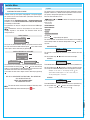 4
4
-
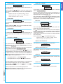 5
5
-
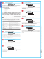 6
6
-
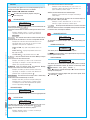 7
7
-
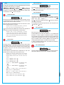 8
8
-
 9
9
-
 10
10
-
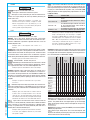 11
11
-
 12
12
-
 13
13
-
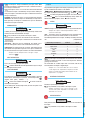 14
14
-
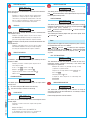 15
15
-
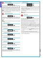 16
16
-
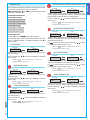 17
17
-
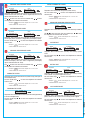 18
18
-
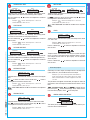 19
19
-
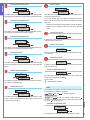 20
20
-
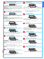 21
21
-
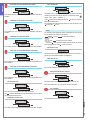 22
22
-
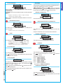 23
23
-
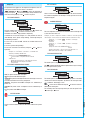 24
24
-
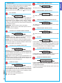 25
25
-
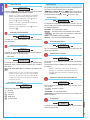 26
26
-
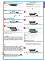 27
27
-
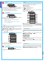 28
28
-
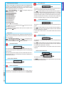 29
29
-
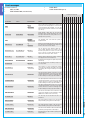 30
30
-
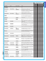 31
31
-
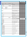 32
32
-
 33
33
-
 34
34
-
 35
35
-
 36
36


CAME PROXINET Installation guide
- Category
- Security access control systems
- Type
- Installation guide
Ask a question and I''ll find the answer in the document
Finding information in a document is now easier with AI
Related papers
-
CAME 846AA-0070 Programming Manual
-
CAME PROXINET, PXC48-96-200 Programming Manual
-
CAME PROXINET Programming Manual
-
-
-
-
-
-
-
Other documents
-
 Teletek electronics argus Installation, Programming, And User's Manual
-
Comelit VEDO 2.6 Series Programming Manual
-
Pyronix Enforcer 32WE Engineer Reference Manual
-
-
-
Ness SmartLiving 505 Installation & Programming Manual
-
Hikvision Pyronix EURO 280 Programming Manual
-
-
-
