
® U.S. Registered Trademark
Copyright © 1997 Honeywell Inc. • All Rights Reserved
SERVICE DATA
TP970 and TP9600 Series
Pneumatic Thermostats
75-7134-1
GENERAL
The TP970 and TP9600 Series Pneumatic Thermostats are
one-, two-, or three-pipe, proportioning thermostats with
bimetal elements. They are suitable for controlling dampers
and/or valves in HVAC systems.
APPLICATION
TP970A-D and TP9600A,B
The TP970 and TP9600 are single-temperature, pilot-bleed,
two-pipe thermostats. The TP970A and TP9600A are used for
heating (Direct Acting [DA]), the TP970B and the TP9600B for
cooling (Reverse Acting [RA]), and the TP970C and D for
heating/cooling. There are TP970A and B models with Limited
Control Range (LCR) for energy conservation. The TP970C
and D have a wide throttling range capability, allowing an
adjustable Zero Energy Band (ZEB) between heating and
cooling operations.
TP971A-E and TP9610A,B
The TP971A-E and TP9610A,B are two-temperature, pilot-
bleed, two-pipe thermostats for DAY/NITE operation, with
automatic switchover from mainline pressure. The TP971C is
a three-pipe thermostat for unit ventilator DAY/NITE
application.
TP972A and TP9620A
The TP972A and TP9620A are single-temperature, pilot-
bleed, two-pipe thermostats with cooling/heating cycles and
automatic switchover from mainline pressure. The
TP972A2143 is designed specifically for replacing Johnson
cooling/heating thermostats (see SPECIFICATIONS section).
TP973A,B and TP9630A,B
The TP973A, B and TP9630A,B are one- or two-pipe bleed-
type thermostats for heating or cooling applications.
TP974A
The TP974A is a pneumatic space temperature sensor for
either one- or two-pipe applications. It is suitable as a remote
temperature indicator or as the sensor for a receiver
controller.
TP978A-E
The TP978 is a dual-element bleed-type thermostat used in
dual one-pipe applications, suitable for use with variable
volume systems. These thermostats may be used to control
separate heating and cooling actuators in sequence, with a
Zero Energy Band (ZEB) for energy conservation. The
heating setpoint is limited to 73F (23C) maximum, and the
cooling setpoint is limited to 77F (25C) minimum. Heating and
cooling are available in both DA and RA configurations.
Except for the TP978E, there are no upgraded replacements
for the TP978.
TP979A-E
The TP979 contains two cooling/heating, DAY/NITE
thermostats. They are one- or two-temperature, two-pipe
thermostats for independent proportioning control of heating
and cooling.
Contents
General ............................................................................... 1
Application .......................................................................... 1
Specifications ...................................................................... 2
Operation ............................................................................ 8
Maintenance ....................................................................... 11
General ............................................................................... 11
Cleaning .............................................................................. 11
Calibration ........................................................................... 12
Troubleshooting .................................................................. 14
Repair.................................................................................. 15
Parts and Accessories ........................................................ 18
Accessories ......................................................................... 21

2
TP970 AND TP9600 SERIES PNEUMATIC THERMOSTATS
75-7134—1
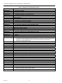
SPECIFICATIONS
Maximum Safe Air Pressure:
25 psi (172 kPa)
Maximum Safe Temperature:
150F (66C)
(continued)
See Tables 1 though 6 for additional specifications. These
tables represent the direct replacements of existing
thermostats at the time of the introduction of the 2000 series
of thermostats. For replacement parts, see PARTS and
ACCESSORIES.
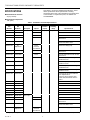
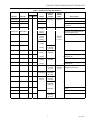
Table 1. TP970A-D Thermostat Specifications.*
Old
Model No.
New
Model No. Description Setpoint
Supply Air
Pressure
psi (kPa)
Degrees
Throttling
Range Special Features
TP970A 1004 TP970A 2004
DA,
60-90°F 18 (124) Adjustable —
TP970A 1012 TP970A 2012
2-Pipe
4079°F 2-10°F—
TP970A 1020 TP970A 2020 15-30°C (1.1-5.6°C) —
TP970A 1038 TP970A 2038 60-90°F Universal Modernization Kit with Universal
Window Cover
TP970A 1053 TP970A 2053 Honeywell Thermostat Modernization Kit
with Universal Window Cover
TP970A 1062 No
Replacement
60-90°F
Controls at
72°F Maximum
Limited Control Range (LCR)
TP970A 1087 TP970A 2087 60-72°F Universal Modernization Kit with Universal
Window Cover
TP970A 1095 TP970A 2095 40-70°F Universal Modernization Kit with Universal
Window Cover
TP970A 1103 TP970A 2103 60-90°F Includes 25 ft (7.6m) Twin Tubing and
14004407-300 Cover
TP970A 1111 TP970A 2111 Includes 25 ft (7.6m) Twin Tubing and
14004407-121 Cover
TP970A 1129 TP970A 2129 Includes 25 ft (7.6m) Sheathed Tubing and
14004406-300 Cover
TP970A 1137 TP970A 2137 Includes 25 ft (7.6m) Sheathed Tubing and
14004406-121 Cover
TP970A 1145 TP970A 2145 Convertastat Kit with Universal Window
Cover. Replacement for
2-pipe only; Johnson T4002 & T4100,
Powers TH192, Robertshaw TP2211 &
TP2212
— TP970A 2152 Quick Mount with 14004407-300 Cover
— TP970A 2160 Quick Mount with 14004407-121 Cover
— TP970A 2178 Quick Mount with 14004407-111 Cover
— TP970A 2186 Quick Mount with 14004406-300 Cover
— TP970A 2194 Quick Mount with 14004406-121 Cover
— TP970A 2202 Quick Mount with 14004406-111 Cover
TP970B 1002 TP970B 2002 RA, 2-Pipe —
TP970B 1010 TP970B 2010 15-30°C—
TP970B 1028 TP970B 2028 60-90°F Universal Modernization Kit with Universal
Window Cover
TP970B 1036 TP970B 2036 Honeywell Thermostat Modernization Kit
with Universal Window Cover
TP970B 1044 No
Replacement
60-90°F
Controls at
78°F Minimum
Limited Control Range (LCR)
*All single-temperature, pilot bleed.

TP970 AND TP9600 SERIES PNEUMATIC THERMOSTATS
3
75-7134—1
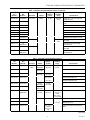
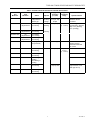
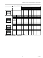
Table 1. TP970A-D Thermostat Specifications (continued).*
Table 2. TP971A-E Thermostat Specifications.*
(continued)
Old
Model No.
New
Model No. Description Setpoint
Supply Air
Pressure
psi (kPa)
Degrees
Throttling
Range Special Features
TP970B 1069 TP970B 2069 RA, 2-Pipe 60-90°F 18 (124)
Adjustable
2-10°F
Includes 25 ft (7.6m) Twin Tubing with
1400406-121 Cover
TP970B 1077 TP970B 2077
(1.1-5.6°C)
Convertastat Kit with Universal Window
Cover
— TP970B 2085 Quick Mount with 14004407-300 Cover
— TP970B 2093 Quick Mount with 14004407-121 Cover
— TP970B 2101 Quick Mount with 14004407-111 Cover
— TP970B 2119 Quick Mount with 14004406-300 Cover
— TP970B 2127 Quick Mount with 14004406-121 Cover
— TP970B 2135 Quick Mount with 14004406-111 Cover
TP970C 1000 TP970C 2000 DA, 2-Pipe
Adjustable
5-25F
Wide Throttle Range Allows Zero Energy
Band (ZEB)
TP970C 1018 No
Replacement
(2.8-13.9C)
Universal Zero Energy Band (ZEB)
Modernization Kit
TP970D 1008 TP970D 2000 RA, 2-Pipe Wide Throttle Range Allows Zero Energy
Band (ZEB)
TP970D 1016 No
Replacement
Universal Zero Energy Band (ZEB)
Modernization Kit
*All single-temperature, pilot bleed.
Old
Model No.
New
Model No. Description Setpoint
Supply Air
Pressure
psi (kPa)
Degrees
Throttling
Range Special Features
TP971A 1003 TP971A 2003 DA, Heating,
2-Pipe
60-90°F
DAY Range
13 or 18
(90 or 124)
Adjustable
2-10°F
—
TP971A 1011 TP971A 2011 15-30°C
DAY Range
(1.1-5.6°C) —
TP971A 1029 TP971A 2029 60-90°F
DAY Range
16 or 21
(110 or 145)
—
TP971A 1037 TP971A 2037 13 or 18, 16 or Universal Modernization Kit
21 (90 or 124,
110 or 145)
Honeywell Thermostat Modernization Kit
with Universal Window Cover
TP971A 1052 TP971A 2052 15-30°C
DAY Range
16 or 21
(110 or 145)
—
TP971A 1060 TP971A 2060 60-90°F
DAY Range
Includes 14004406-901 Cover
TP971A 1078 No
Replacement
60-90°F
50-75°F
13 or 18
(90 or 124)
Adjustable 5-
25°F (2.8-
13.9°C)
DAY, 2-10°F
(1.1-5.6°C) NITE
—
TP971A 1086 TP971A 2086 60-90°F 20 or 25 Adjustable —
TP971A 1094 TP971A 2094 DAY Range (138 or 172) 2-10°F
(1.1-5.6°C)
Includes 25 ft (7.6m) Twin Tubing and
14004407-121 Cover
TP971A 1102 TP971A 2102 13 or 18, or 16
or 20 (90 or
124, or 110 or
145)
Convertastat Kit with Universal Window
Cover
*All DAY/NITE, two-temperature, pilot-bleed.

4
TP970 AND TP9600 SERIES PNEUMATIC THERMOSTATS
75-7134—1
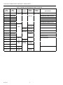
Table 2. TP971A-E Thermostat Specifications (continued).*
Old
Model No.
New
Model No. Description Setpoint
Supply Air
Pressure
psi (kPa)
Degrees
Throttling
Range Special Features
— TP971A 2110 DA, Heating,
2-Pipe
60-90°F
DAY Range
13 or 18 Adjustable 2-
10°F (1.1-5.6°C)
Quick Mount with 14004407-300 Cover
— TP971A 2128 (90 or 124) Quick Mount with 14004407-121 Cover
— TP971A 2136 Quick Mount with 14004407-111 Cover
— TP971A 2144 Quick Mount with 14004406-300 Cover
— TP971A 2151 Quick Mount with 14004406-121 Cover
— TP971A 2169 Quick Mount with 14004406-111 Cover
TP971B 1001 TP971B 2001 RA, —
TP971B 1019 TP971B 2019 Heating,
2-Pipe
16 or 21
(110 or 145)
—
TP971B 1027 TP971B 2027 15-30°C
DAY Range
13 or 18
(90 or 124)
—
TP971B 1035 TP971B 2035 60-90°F
DAY Range
16 or 21
(110 or 145)
Includes 14004406-901 Cover
TP971B 1043 TP971B 2043 20 or 25 —
TP971B 1050 TP971B 2050 (138 or 172) Includes 25 ft (7.6m) Twin Tubing with
14004407-121 Cover
TP971C 1009 TP971C 2009 DA, 13 or 18, With Secondary Branch
TP971C 1017 TP971C 2017 Heating,
3-Pipe
15-30°C
DAY Range
(90 or 124)
TP971C 1025 TP971C 2025 DA,
Cooling,
60-90°F
DAY Range
16 or 21
(110 or 145)
TP971C 1041 TP971C 2041 3-Pipe 20 or 25
TP971D 1007 TP971D 2007 DA, Cooling,
2-Pipe
(138 or 172) NITE Set-Up (75 to 100F)
TP971E 1004 TP971E 2004 RA, Cooling,
2-Pipe
13 or 18
(90 or 124)
*All DAY/NITE, two-temperature, pilot-bleed.

TP970 AND TP9600 SERIES PNEUMATIC THERMOSTATS
5
75-7134—1
Table 3. TP972A Thermostat Specifications.*
Action
Supply Air Degrees
Old
Model No.
New
Model No.
Left
Bimetal
Right
Bimetal Setpoint
Pressure
psi (kPa)
Throttling
Range
Special Features
TP972A 1002 TP972A 2002 60-90°F 13 (Cooling) or Adjustable —
TP972A 1010 TP972A 2010 R.A. D.A. 15-30°C 18 (Heating) 2-10°F—
TP972A 1028 TP972A 2028 60-90°F (90 or 124) (1.1-5.6°C) Universal Modernization Kit with Universal
Window Cover
TP972A 1036 TP972A 2036 60-90°F
(Cooling)
Energy Conservation, Separate Setpoints
TP972A 1044 TP972A 2044 (50-75°F
(Heating)
Honeywell Thermostat Modernization Kit
with Universal Window Cover
TP972A 1051 No Replacement 78-90°F
(Cooling)
60-72°F
(Heating)
Separately
Adjustable
2-10°F
(1.1-5.6°C)
Limited Control Range (LCR)
TP972A 1077 No Replacement 75-90°F
(Cooling)
Setpoint Stop at 75F Minimum
TP972A 1085 No Replacement 50-75°F
(Heating)
16 (Cooling) or
21 (Heating)
(110 or 145)
TP972A 1093 No Replacement 78-90°F
(Cooling)
13 (Cooling) or
18 (Heating)
Limited Control Range (LCR)
TP972A 1101 No Replacement 60-72°F
(Heating)
(90 or 124) Universal Limited Control Range (LCR)
Modernization Kit
TP972A 1119 No Replacement 78-90°F
(Cooling)
13 (Cooling) or
18 (Heating)
Limited Control Range (LCR)
TP972A 1127 No Replacement 55-65°F
(Heating)
(90 or 124) Universal Limited Control Range (LCR)
Modernization Kit
TP972A 1143 TP972A 2143 D.A. R.A. 60-90°F 14 (Heating) or
19 (Cooling)
(97 or 131)
Separately
Adjustable
2-10°F
Specifically for replacing Johnson
Cooling/Heating Thermostats
TP972A 1150 TP972A 2150 R.A. D.A. 15-30°C Cooling
12-24 Heating
13 (Cooling) or
18 (Heating)
(90 or 124)
(1.1-5.6°C) Energy Conservation, Separate Setpoints
TP972A 1168 TP972A 2168 D.A. R.A. 60-90°F
(Cooling)
50-75°F
16 (Cooling) or
21 (Heating)
110 or 145)
TP972A 1176 TP972A 2176 D.A. R.A. (Heating) 20 (Cooling) or
25 (Heating)
(138 or 172)
TP972A 1184 TP972A 2184 13 (Cooling or
18 (Heating)
Includes 14004406-901 Cover, Separate
Setpoints
— TP972A 2192 R.A. D.A. 60-90°F (90 or 124) Includes Universal Window Cover
— TP972A 2200 D.A. R.A. 14 (Cooling) or
19 (Heating)
(97 or 131)
—
*All single-temperature, tw0-pipe, two-element, automatic changeover, and cooling/heating.

6
TP970 AND TP9600 SERIES PNEUMATIC THERMOSTATS
75-7134—1
Table 4. TP973A and B Thermostat Specifications.*
Old
Model No.
New
Model No. Action Setpoint
Supply Air
Pressure
psi (kPa)
Degrees
Throttling
Range Special Features
TP973A 1068 TP973A 2068 DA 60-90°F 18 (124)
Adjustable
2-10°F
Universal Modernization Kit with Universal
Window Cover
TP973A 1076 TP973A 2076
(1.1-5.6°C)
—
TP973A 1084 TP973A 2084 15-30°C—
TP973A 1092 TP973A 2092 60-90°F Honeywell Thermostat Modernization Kit with
Universal Window Cover
TP973A 1100 TP973A 2100 Includes 14004406-901 Cover
TP973A 1117 No Replacement Includes 25 ft (7.6m) Twin Tubing and
TP973A 1126 No Replacement Blank Plastic Cover
TP973A 1134 No Replacement
TP973A 1142 No Replacement
TP973A 1159 TP973A 2159 —
TP973A 1167 TP973A 2167 Includes 14004407-121 Cover
TP973A 1175 TP973A 2175 Includes 14004407-300 Cover
TP973A 1183 TP973A 2183 —
TP973B 1066 TP973B 2066 RA —
TP973B 1074 TP973B 2074 15-30°C—
TP973B 1090 TP973B 2090 60-90°F Includes 1400406-901 Cover
TP973B 1108 TP973B 2108 —
TP973B 1116 TP973B 2116 —
TP973B 1124 TP973B 2124 15-30°C—
TP973B 1132 TP973B 2132 60-90°F Includes 14004407-121 Cover
TP973B 1140 TP973B 2140 Includes 14004407-300 Cover
TP973B 1157 TP973B 2157 Includes 25 ft (7.6m) Twin Tubing and
14004407-121 Cover
*All one- or two-pipe, bleed type.

TP970 AND TP9600 SERIES PNEUMATIC THERMOSTATS
7
75-7134—1
Table 5. TP974A, TP978A-E, TP979A-E Thermostat Specifications.
Old
Model No.
New
Model No. Action Setpoint
Supply Air
Pressure
psi (kPa)
Degrees
Throttling
Range Special Features
TP974A 1000 TP974A 2000 DA, 1- or
2-Pipe Sensor
Bleed Type
50-100°F
(10-38°C)
Range
18 (124)
3-15 (21-103)
Output
— Sensor for use with
RP908 & RP920
Controller
TP978A 1006 No
Replacement
DA Heating
DA Cooling
60-73°F
Heating
18 (124) 2-10°F
(1.1-5.6°C)
ZEB Energy
Conservation, Setpoint
Stop 73°F (Heating),
77°F (Cooling)
TP978B 1004 No
Replacement
RA heating
DA Cooling
77-90°F
Cooling
TP978C 1002 No
Replacement
DA Heating
RA Cooling
TP978D 1000 No
Replacement
RA Heating
RA Cooling
TP978E 1007 TP978E 2007 RA (Right Side)
DA (Left Side)
68-82°F 0.18 (1) 1-4°F Includes Cover
Special System-
Powered Thermostat
for Carrier
TP979A 1005 TP979A 2005 DA Heating
DA Cooling
60-90°F 18 (124) Adjustable
2-10°F
(1.1-5.6°C)
—
TP979B 1003 TP979B 2003 RA Heating
RA Cooling
—
TP979C 1001 TP979C 2001 DA Heating or
Cooling
RA Heating or
Cooling
—
TP979D 1009 TP979D 2009 DA Heating
DA Cooling
13 (90) Day
18 (124) Nite
Day/Nite Heat with
night set down; Cool
with night set up.
TP979E 1006 TP979E 2006 DA Heating
RA Cooling

8
TP970 AND TP9600 SERIES PNEUMATIC THERMOSTATS
75-7134—1
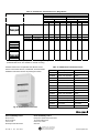
Table 6. TP9600 Thermostat Specifications.
Model No. Description Setpoint Slot Includes Stat.
Single Temperature, Two-Pipe:
TP9600A 1007 DA, Open Windows Open TP970A 2004
TP9600B 1006 RA, Open Windows Open TP970B 2002
TP9603A 1001 DA, Close Windows Closed TP970A 2004
TP9603B 1000 RA, Close Windows Closed TP970B 2002
Day/Night, Two-Pipe:
TP9610A 1006 DA, Open Windows Open TP971A 2003
TP9610B 1005 RA, Open Windows Open TP971B 2001
TP9613A 1000 DA, Close Windows Closed TP971A 2003
TP9613B 1009 RA, Close Windows Closed TP971B 2001
Heating/Cooling, Two-Pipe:
TP9620A 1005 DA, Open Windows Open TP972A 2002
TP9623B 1009 RA, Close Windows Closed TP972B 2002
Single Temperature, One or Two-Pipe:
TP9630A 1004 DA, Open Windows Open TP973A 2076
TP9630B 1003 RA, Open Windows Open TP973B 2066
TP9633A 1008 DA, Close Windows Closed TP973A 2076
TP9633B 1007 RA, Close Windows Closed TP973B 2066
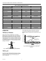
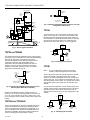
OPERATION
TP970A,B and TP9600A,B
When using a TP970A or TP9600A (Fig. 1) in heating
applications with a normally open valve, a fall in temperature
lowers Branchline Pressure (BLP) to the valve. THis lower
BLP provides proportional valve action matching the existing
load requirements. When a TP970B or TP9600B is used in a
cooling application, a rise in temperature causes the TP970B
or TP9600B to lower BLP. The energy conservation models
limit control temperature to a maximum (heating) or minimum
(cooling) of 72F (24C).
SUPPLY
TP970A,B OR
TP9600A,B
N.O.
M B
M
C3535-1
Fig. 1. TP970A,B and TP9600A,B Typical Operation.
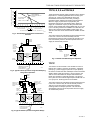
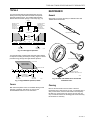
TP970C and D
The TP970C and D with wide throttling range (Fig. 2 and 3)
allow use of heating and cooling valve assemblies with either
selected spring ranges (Fig. 4) or ratio relays (Fig. 5) to
achieve a ZEB range.
Various ZEB ranges, heating control points, and cooling
control points are obtained by selecting the appropriate
thermostat setpoint, throttling range, and spring range or ratio
relays.
15
14
13
12
11
10
9
8
7
6
5
4
3
2
1
(100)
(90)
(80)
(70)
(60)
(50)
(40)
(30)
(20)
(10)
0
15
12.5 10 7.5 5 2.5 1512.5107.552.5
SETPOINT
SETPOINT
(8) (7) (6) (5) (4) (3) (2) (1) (8)(7)(6)(5)(4)(3)(2)(1)
BRANCHLINE PRESSURE—PSI (kPa)
DEVIATION IN SPACE TEMPERATURE—DEGREES F (C)
BELOW SETPOINT ABOVE SETPOINT
C3536
TP970C MINIMUM
THROTTLING RANGE =
5F (2.8C)
TP970C MAXIMUM
THROTTLING RANGE =
20F (11.1C)
Fig. 2. TP970C Space Temperature vs. Branchline
Pressure.

TP970 AND TP9600 SERIES PNEUMATIC THERMOSTATS
9
75-7134—1
15
14
13
12
11
10
9
8
7
6
5
4
3
2
1
(100)
(90)
(80)
(70)
(60)
(50)
(40)
(30)
(20)
(10)
0
15
12.5 10 7.5 5 2.5 1512.5107.552.5
SETPOINT
SETPOINT
(8) (7) (6) (5) (4) (3) (2) (1) (8)(7)(6)(5)(4)(3)(2)(1)
BRANCHLINE PRESSURE—PSI (kPa)
DEVIATION IN SPACE TEMPERATURE—DEGREES F (C)
BELOW SETPOINT
ABOVE SETPOINT
C3537
TP970D MINIMUM
THROTTLING RANGE =
5F (2.8C)
TP970D MAXIMUM
THROTTLING
RANGE = 20F (11.1C)
Fig. 3. TP970D Space Temperature Vs Branchline
Pressure.
VALVE
OPEN
VALVE
CLOSED
4 DEGREES F
(2.2 DEGREES C)
ZERO
ENERGY
BAND
THERMOSTAT SETTING
TR=10 DEGREES F
(5.6 DEGREES C)
20C
22C
24C
66F 68F 70F 72F 74F 76F 78F
TP970C
DIRECT
ACTING
COOLING
VALVE
9 TO 13 PSI
(62 TO 90 kPa)
SPRING
HEATING
VALVE
2 TO 5 PSI
(14 TO 34 kPa)
SPRING
N.C.
N.O.
M B
M
C3538
Fig. 4. Typical TP970C Operation Using Selected Spring
Range Valve Operators.
TP970C
DIRECT
ACTING
HEATING
VALVE
3 TO 10 PSI
(21 TO 68.9 kPa)
COOLING
VALVE
3 TO 10 PSI
(21 TO 68.9 kPa)
RP971A—3 PSI
RANGE—SET
10 PSI (68.9 kPa)
START
RP971A—3 PSI
SPAN—SET
3.9 PSI (26.9 kPa)
START
M
M
M B
2
1
4
3
EXH
N.O.
M
2
1
4
3
EXH
N.C.
C3539
VALVE
OPEN
VALVE
CLOSED
20C
22C
24C
66F 68F 70F 72F 74F 76F 78F
4 DEGREES F
(2.2 DEGREES C)
ZERO
ENERGY
BAND
THERMOSTAT SETTING
TR=10 DEGREES F
(5.6 DEGREES C)
Fig. 5. Typical TP970C Operation Using Ratio Relays.
TP971A, B, D, E and TP9610A,B
These thermostats provide a BLP proportional to the ambient
temperature. In a heating application with a normally open
valve (Fig. 6), a fall in room temperature causes the
thermostat to lower the BLP to the valve, providing a
proportional action matching the existing load requirement.
When the supply air pressure is 13 psi (90 kPa), the
thermostat controls at the normal DAY setting. When the
supply air is switched to 18 psi (124 kPa), the thermostat
controls at the reduced NITE setting. Models with 16 or 21 psi
(110 or 145 kPa) pressure are available. The TP971D is the
same as the TP971A with the addition of NITE setup. The
TP971E is the same as the TP971B with the addition of NITE
setup.
The manual reset lever protrudes through the DAY/AUTO slot
in the cover. The lever is used to manually reset the
thermostat from AUTO to DAY to restore day operation. The
lever automatically returns to the AUTO position when the
supply air reaches DAY pressure.
TP971A OR
TP9610A
DAY
13 PSI
(90 kPa)
NITE
18 PSI
(124 kPa)
M B
N.O.
M
HOT WATER
OR STEAM
SUPPLY
C3540-1
Fig. 6. TP971A and TP9610A Typical Operation.
TP971C
The TP971C can be used with a unit ventilator to control a
heating valve, outdoor- and return-air dampers, and blower
motor (Fig. 7). When supply air pressure is 13 psi (90 kPa),
the TP971C controls the valve and damper at the normal DAY
setpoint. When supply air pressure is 18 psi (125 kPa), the
TP971C closes the outdoor-air damper and switches the
blower from constant to automatic operation. The TP971C
then cycles the unit at reduced night setpoint. Models with 18
or 21 psi (125 or 145 kPa) pressure are available.
The manual reset lever protrudes through the DAY/AUTO slot
in the cover. The lever may be used to manually reset the
TP971C from AUTO to DAY to restore DAY operation,
including outdoor-air damper operation. The reset lever
automatically returns to the AUTO position when the supply
air reaches DAY pressure.

10
TP970 AND TP9600 SERIES PNEUMATIC THERMOSTATS
75-7134—1
12
M
HI
LO
N.C. N.O.
D/N
MP516C
FAN
P638
G
TP971
C
VALVE
HEATING
COIL
H
120V AC
50/60 HZ
AIR
STREAM
STAT
13/18 PSI
(90/124 kPa)
D/N
MSB K H
FILTER
DISCHARGE AIR
OUTDOOR
AIR
RETURN
AIR
C3541
Fig. 7. TP971C Typical Operation.
TP972A and TP9620A
The standard TP972Aand TP9620A is RA for cooling and DA
for heating. A rise in temperature at the TP972Aand TP9620A
with main air pressure at 13 psi (90 kPa) causes the
TP972Aand TP9620A to lower BLP, opening the valve to
control the temperature with chilled water. A fall in
temperature at the TP972Aand TP9620A with main air
pressure at 18 psi (124 kPa) causes the TP972Aand
TP9620A to lower BLP, opening the valve to control the
temperature with hot water (Fig. 8).
TP972A OR
TP9620A
13 PSI
(90 kPa) RA
18 PSI
(124 kPa)
DA
N.O.
M B
S/W
HOT WATER/CHILLED
WATER SUPPLY
C3542-1
Fig. 8. TP972A and TP9620A Typical Operation with a
Normally Open Water Valve Assembly.
Models are available that limit the cooling setpoint to a
minimum of 75 or 78F, the heating setpoint to a maximum of
72 or 75F. They work with 13/18, 16/21, 25/20, 19/14, or 20/
25 psi changeover. Some models are DA for both cooling and
heating.
TP973A,B and TP9630A,B
A fall in temperature at the TP973A or TP9630A causes the
TP973A or TP9630A to lower BLP, providing proportional
control of existing load requirements for heating (Fig. 9). A
rise in temperature at the TP973B or TP9630B causes the
TP973B or TP9630B to lower BLP, providing proportional
control of existing load requirements for cooling.
Fig. 9. TP973A and TP9630A Typical Operation, One-Pipe
Using External Restriction.
TP974A
The TP974A Sensor (Fig. 10) provides a pneumatic output
signal of 3 to 15 psi (21 to 103 kPa) in direct relation to the
sensed temperature, allowing direct and remote readout of
the temperature. An RP908 or RP920 Controller is used with
the TP974A to convert the output into a usable signal to
operate a pneumatic valve, damper, or other equipment.
TP973A OR
TP9630A
M
N.O.
HOT WATER OR
STEAM SUPPLY
C3543-1
TP974
VALVE
TEMP
GAGE
4 8 9
2 3 1
M
RP920
C3544A
MB
Fig. 10. TP974 Typical Operation.
TP978E
NOTE: To vary the ZEB between heating and cooling
operation, adjust the setpoints on the TP978E.
A fall in temperature within the cooling range at the TP978E
causes the TP978E to increase the BLP of the cooling
element. This action proportionally closes the normally open
cooling valve (Fig. 11) to maintain the temperature set on the
high range portion of the TP978E. The normally open heating
valve is held closed by the high BLP on the DA side of the
TP978E.
A continued fall in temperature, into the heating range at the
TP978E, lowers the BLP of the heating element. This action
proportionally opens the normally open heating valve to
maintain the temperature set on the low range portion of the
TP978E.
DA RA
TP978E
M
HEATING
VALVE
COOLING
VALVE
H C
N.O. N.O.
C3545
EXTERNAL
RESTRICTORS
0.005
Fig. 11. TP978A Typical Operation.

TP970 AND TP9600 SERIES PNEUMATIC THERMOSTATS
11
75-7134—1
TP979A-E
The TP979 thermostats provide independent control of
heating and cooling with dual thermostats and separate
setpoints and branch lines. This enables ZEB operation
without selected actuator springs or ratio relays (Fig. 12).
64F 66F 68F 70F 72F 74F 76F 78F
18C 20C 22C 24C 26C
ZERO
ENERGY
BAND
VALVE CLOSED
HEATING
SETPOINT
COOLING
SETPOINT
VALVE OPEN
TP979C
COOLING VALVE
PNEUMATIC
OPERATOR WITH
4 TO 11 PSI
(28 to 76 kPa)
SPRING RANGE
HEATING VALVE
PNEUMATIC
OPERATOR WITH
4 TO 11 PSI
(28 to 76 kPa)
SPRING RANGE
N.O.
N.O.
H C
M
DA RA
C3546
Fig. 12. TP979 Typical Operation.
The TP979D and E models provide automatic night setback
of setpoint for heating and setup for cooling. Figure 13 shows
potential energy savings with night setback operation.
VALVE CLOSED
NIGHT
HEATING
SETPOINT
DAY
COOLING
SETPOINT
VALVE OPEN
64F 66F 68F 70F60F 62F
18C 20C 22C16C
6 DEGREES F
(3.3 DEGREES C)
NIGHT SETBACK
NIGHT SETBACK
ENERGY SAVINGS
C3547
Fig. 13. Night Setback Operation, TP979.
Covers
Both metal and plastic covers are available offering a wide
selection of windows. See Tables 11 and 12 in the
ACCESSORIES section for more information.
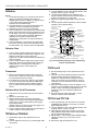
MAINTENANCE
General
See Figure 14 for tools necessary to calibrate TP970 and
TP9600 Series thermostats.
Fig. 14. TP970 and TP9600 Series Thermostat
Calibration Tools.
Cleaning
Remove the thermostat cover and clean or dust the
thermostat using a soft brush or air hose. In extremely dirty or
dusty environments, clean the thermostats more frequently.
DO NOT use a high pressure air hose to remove dust. Use
only a soft brush to clean the throttling plate nozzle assembly.
No lubrication is necessary.
C3929
GAGE PORT NEEDLE
DIGITAL RELATIVE
HUMIDITY INDICATOR PEN
100
120
140
160
180
80
60
200
220
40
20
0
10
25
30
20
15
5
0
GAGE
TEST THERMOMETER
THERMOSTAT TOOL

12
TP970 AND TP9600 SERIES PNEUMATIC THERMOSTATS
75-7134—1
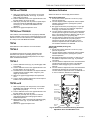
Calibration
NOTES:
1. The antihum spring (Fig. 15) must be free. Be sure the
spring just touches the throttling plate and is not
wedged against it (does not apply to all TP970C and D
or any TP970 series starting with 2000, i.e.,
TP972A2143 and TP9600 series).
2. The thermostats are very sensitive and should not be
heated by excessive handling during calibration.
3. Calibration of the TP974 is not recommended.
4. To check calibration or to recalibrate the Limited Control
Range (LCR) thermostats, the space temperature must
be 78F (26C) or above for cooling applications, and 72
or 68F (22 or 20C) or below for heating applications,
depending on the model. TP972A1119 and
TP972A1127 are 68F (20C). The setpoint limitation is
nonadjustable.
5. To check calibration or to recalibrate the TP978 ZEB
thermostats, measure actual room temperature with a
test thermometer. The 75F (24C) limit is nonadjustable.
Calibration Check
1. Turn the setpoint indicator adjustment down (DA) or up
(RA) until the setpoint indicator reads 5 degrees F (2.8
degrees C) below (DA) or above (RA) room
temperature. The BLP at the thermostat should build up
within 30 seconds.
2. Turn the setpoint indicator adjustment up (DA) or down
(RA) slowly. The thermostat should begin to bleed off
audibly between 1 and 3 degrees F (0.56 and 1.7
degrees C) below (DA) or above (RA) room
temperature.
Thermometers
1. Measure the ambient temperature with an accurate
thermometer. Compare the thermometer reading with
the thermostat thermometer reading.
2. If the difference is more than 1 degree F (0.56 degree
C), use the Thermometer Calibration Tool MQT970 to
twist the thermostat thermometer calibration bobbin
(Fig. 15) until the thermostat thermometer reading is
correct.
Calibration Set-Up (For All Thermostats)
1. Start with the main air pressure at the recommended
setting.
2. Remove the thermostat cover.
3. All thermostats except the TP978E: Install Gage
305965 (0 to 30 psi [0 to 207 kPa]) with Gage Adapter
315161A (Fig. 14) into the branchline pressure gage
tap (except TP978E).
TP978E: Install a 0 to 30 psi (0 to 207 kPa) gage in the
branchline remote from the TP978E.
4. Turn the setpoint indicator adjustment until the setpoint
indicator reads the existing temperature.
TP970A,B and TP9600A,B
1. Set throttling range to value specified on the job
drawing.
2. Turn the calibration screw (Fig. 15) until the gage reads
0 psi (0 kPa).
3. Turn the calibration screw in the opposite direction until
the gage reads 8 ±1 psi (55 ±7 kPa).
4. The TP970 and TP9600 are now calibrated. The
setpoint indicator and thermometer should be within 1
degree F (0.56 degree C) of each other.
5. Remove the gage and gage adaptor and replace the
cover.
6. Turn the setpoint indicator adjustment until the setpoint
indicator is at the desired setting.
7060 80 90
ANTIHUM
SPRING (2)
THROTTLING
RANGE
ADJUSTMENT (2)
(NITE/WINTER)
SETPOINT DIAL
(NITE/WINTER)
THERMOMETER
CALIBRATION
BOBBIN
SETPOINT
INDICATOR
(NITE/WINTER)
SETPOINT
INDICATOR
CALIBRATION
SCREW
(DAY/SUMMER)
DAY/AUTO LEVER
(TP971 ONLY)
SETPOINT INDICATOR
ADJUSTMENT
C3946-3
5
5
5
6
7
SCALEPLATE
MAX
MAX
THROTTLING RANGE
SCALE (2)
(DAY/SUMMER)
THROTTLING
PLATE (2)
GAGE TAP
NOTE: NOT ALL ADJUSTMENTS ARE ON ALL THERMOSTATS.
TEMPERATURE
INDICATOR
STOPS
TEMPERATURE
SETTING
Fig. 15. Thermostat Front View, Cover Off, Showing
Controls and Indicators.
TP970C and D
1. Set the throttling range to value specified on the job
drawing.
2. Check the mechanical throttling range by turning the
setpoint indicator adjustment to determine the
difference in setpoint indicator readings when BLP
reads 3 psi (21 kPa) and 13 psi (90 kPa). It may be
necessary to turn the calibration screw to obtain this
measurement.
3. Reset the throttling range to within ±2 degrees F (±1.1
degrees C) of the specified throttling range for accurate
control. If either the throttling range adjustment or
calibration screw were changed, recalibrate the
thermostat.
4. See TP970A and B, beginning at Step 1, for the
balance of TP970C and D calibration.
TP971A-E and TP971A,B
1. With 13 psi (90 kPa) main air pressure, turn the DAY
(SUMMER) (left) calibration screw (Fig. 15) until the
gage reads 0 psi (0 kPa).
2. Turn the calibration screw in the opposite direction until
the gage reads 8 ±1 psi (55 ±7 kPa).
3. With 18 psi (124 kPa) main air pressure, rotate the
NITE (WINTER) setpoint dial until the setting agrees
with the indicated temperature.
4. Repeat Steps 1 and 2 using the NITE (WINTER) (right)
calibration screw (Fig. 15). The TP971 is now
calibrated.
5. Remove the gage and replace the cover.

TP970 AND TP9600 SERIES PNEUMATIC THERMOSTATS
13
75-7134—1
TP972A and TP9620A
1. With 13 psi (90 kPa) main air pressure, turn the DAY
(SUMMER) (left) calibration screw (Fig. 15) until the
gage reads 0 psi (0 kPa).
2. Turn the calibration screw in the opposite direction until
the gage reads 8 ±1 psi (55 ±7 kPa).
3. With 18 psi (124 kPa) main air pressure, repeat Steps 1
and 2 using the NITE (WINTER) (right) calibration
screw (Fig. 15). The TP972 and TP9620 are now
calibrated.
4. Remove the gage and replace the cover.
TP973A,B and TP9630A,B
If the TP973A, B and TP9630A,B are not properly calibrated
but the remainder of the system is operating properly, turn the
calibration screw until the TP973A, B or TP9630A,B performs
as in Step 2 under CALIBRATION CHECK.
TP974A
Field calibration of the TP974A is not recommended.
TP978A-E
If a TP978 thermostat is not properly calibrated but the
remainder of the system is operating properly, turn the
calibration screw until the thermostat performs as in Step 2
under CALIBRATION CHECK.
TP979A-C
1. Turn the calibration screw (Fig. 15) until the gage reads
0 psi (0 kPa).
2. Turn the calibration screw in the opposite direction until
the gage reads 8 ±1 psi (55 ±7 kPa).
3. The thermostat is now calibrated. The setpoint indicator
and thermometer should be within 1 degree F (0.56
degree C) of each other.
4. Remove the gage and gage adaptor and replace the
cover.
5. Turn the setpoint indicator adjustment until the setpoint
indicator is at the desired setting.
TP979D and E
1. With 13 psi (90 kPa) main line pressure, turn the DAY
(SUMMER) (left) calibration screw (Fig. 15) until the
gage reads 0 psi (0 kPa).
2. Turn the calibration screw in the opposite direction until
the gage reads 8 ±1 psi (55 ±7 kPa).
3. With 18 psi (124 kPa) main air pressure, rotate the
night setpoint dial until the setting agrees with the
indicated temperature.
4. Repeat Steps 1 and 2 using the NITE (WINTER) (right)
calibration screw (Fig. 15). The thermostat is now
calibrated.
5. Remove the gage and replace cover.
Switchover Calibration
Switchover allows for normal supply line fluctuations.
TP971A-E and TP9610A,B
1. Ensure that main line pressure is set to low (13 psi)
pressure requirement.
2. Turn the setpoint indicator adjustment until the setpoint
indicator reads 5 degrees F (2.8 degrees C) below
actual temperature.
3. BLP gage should read 0 psi (0 kPa) (RA) or 13 psi (90
kPa) (DA). If it does not, turn switchover adjustment
screw (Fig. 16) clockwise until it does.
4. Turn the switchover adjustment screw counterclockwise
until the pressure begins to increase (RA) or decrease
(DA). This indicates switchover. Allow the gage to go to
full line pressure (RA) or 0 psi (0 kPa) (DA).
5. Turn the switchover adjustment screw counterclockwise
until pressure decreases to 0 psi (0 kPa) (RA) or
increases to full main line pressure (DA). Turn the
switchover adjustment screw an additional 1/8 to 1/4
turn clockwise. Switchover is calibrated.
TP972A and TP9620A (Cooling, RA;
Heating, DA)
1. Ensure that main line pressure is set to low (13 psi)
pressure requirement.
2. Turn the setpoint indicator adjustment until the setpoint
indicator reads 5 degrees F (2.8 degrees C) below
actual temperature.
3. BLP gage should read 0 psi (0 kPa). If it does not, turn
the switchover adjustment screw (Fig. 16) clockwise
until it does.
4. Turn the switchover adjustment screw counterclockwise
until the pressure begins to increase. This indicates
switchover. Allow the gage to go to full main line
pressure.
5. Turn the switchover adjustment screw counterclockwise
until pressure decreases to 0 psi (switchover point).
Turn the switchover adjustment screw an additional 1/8
to 1/4 turn clockwise. Switchover is calibrated.
M
P
B
M12211
BACK PLATE
SCREWS (4)
THERMOSTAT
MULTISTAGE
FILTER
SWITCHOVER
ADJUSTMENT
SCREW
DAY/AUTO
LEVER
Fig. 16. Back View of Thermostat Showing Switchover
Adjustment Screw and DAY/AUTO Lever.

14
TP970 AND TP9600 SERIES PNEUMATIC THERMOSTATS
75-7134—1
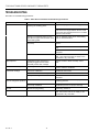
TROUBLESHOOTING
See Table 7 for troubleshooting procedures.
Table 7. TP970 Series Thermostat Troubleshooting Procedures.
Problem Possible Cause Solution*
Excessive noise If there is an antihum spring, it is not
touching the throttling plate.
Reposition spring to touch throttling plate.
Stick an adhesive paper dot on the throttling
plate across the hinge between the two rivets
so that the dot is directly below the “A” in MAX
printed on the bimetal.
If there is no antihum spring or cone,
the adhesive paper dot has fallen off of
the throttling plate.
Stick an adhesive paper dot on the throttling
plate as described above.
Air leak in restrictor block and filter
assembly.
Use a bubble solution to locate the leak and
repair it.
Replace the restrictor block assembly and
filter.
Install Stiffener Plate 14004609-001 on the
backplate.
Oil or moisture in lines. Replace the restrictor block assembly and
filter. Also ensure that the air supply to the
thermostat is dry and clean.
Slow response Inadequate air flow caused by a
partially clogged restrictor block
assembly and/or filter cartridge.
Replace restrictor block assembly and/or
filter.
Thermostat instability System gain is too high. Move throttling range adjustment toward MAX
position and then recalibrate.
Inaccurate readings Inaccurate calibration. Recalibrate thermostat.
Metal cover setscrews over-tightened. Turn setscrews in.
Backplate over-tightened. Install Stiffener Plate 14004609-001 on the
backplate.
Thermostat not switching
over at changeover pressure
Pressure at thermostat is incorrect. Readjust compressed airline to proper
switching pressure.
Switchover pressure in thermostat is
incorrectly calibrated.
Turn switchover adjustment screw to
recalibrate pressure for proper switching.
Air leak Branch line plug leaking. Install Plug 14002172.
Cannot calibrate thermostat Oil or moisture in lines. Replace the restrictor block assembly and
filter. Also ensure that the air supply to the
thermostat is dry and clean.
*If these solutions fail, replace the thermostat.

TP970 AND TP9600 SERIES PNEUMATIC THERMOSTATS
15
75-7134—1
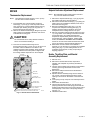
REPAIR
Thermometer Replacement
NOTE: The following procedure requires a 1/4-in. (6 mm)
nut driver and a small screwdriver.
1. Insert the blade of a small screwdriver under the
bimetal (Fig. 17) and pry up. Older style thermostats
have a locking ring. Insert the blade between the ring
and white nylon bushing and pry the ring from the
thermometer bimetal mounting post.
2. Remove the bimetal and bushing by lifting the top of the
plate to which the scaleplate is attached, near the hex
of the bimetal mounting post.
CAUTION
The new bimetal can be easily distorted if extreme
care is not used when handling it.
3. Press the new bimetal and bushing into the
thermometer post using a 1/4-in. (6 mm) nut driver over
the bobbin. Allow the bimetal to cool down to the
ambient temperature after handling. Slowly rotate the
bushing until the thermometer pointer is aligned with
the existing ambient temperature on the scaleplate.
ANTIHUM
SPRING/CONE
BIMETAL
SETPOINT
INDICATOR
SCALEPLATE
MOUNTING POSTS
SCALEPLATE
LOCKING TABS
SETPOINT INDICATOR
ADJUSTMENT
IF THERE IS NO ANTIHUM SPRING/CONE, THERE IS AN
ADHESIVE PAPER DOT ON THE THROTTLING PLATE.
1
1
M11384
Fig. 17. Internal View of Thermostat.
Setpoint Indicator Adjustment Replacement
NOTE: Dual temperature thermostats require removal of
only one of the bimetal assemblies.
1. Remove the setpoint indicator (Fig. 17) by prying it off
the indicator post with a small screwdriver.
2. Remove the thermometer bimetal (Fig. 17) by lifting the
plate to which the scaleplate is attached, at the hex of
the bimetal mounting post.
3. Bend the scaleplate locking tabs (Fig. 17) up and
compress the scaleplate mounting posts (Fig. 17)
together with the thumb and forefinger to free the
scaleplate from the holding notches in the post.
4. Remove and replace setpoint indicator adjustment (Fig.
17), using caution not to damage or distort the bimetal
sensing element(s). On models with DAY-NITE
temperature setpoint wheel (located under the right
sensing element), see the NOZZLE, THROTTLING
PLATE, and BIMETAL ASSEMBLY REPLACEMENT
section for removal of the bimetal and DAY-NITE scale
prior to removing the setpoint indicator adjustment.
5. Reassemble in reverse order and recalibrate if
required. It is not necessary to re-engage the scaleplate
locking tabs (Fig. 17) in the holding notches of the
scaleplate mounting posts, as they are primarily for
shipping purposes.
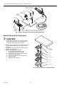
Nozzle, Throttling Plate and Bimetal
Assembly Replacement
1. Remove cover.
2. Remove the thermometer bimetal, temperature
indicator, and scaleplate as previously described, if
applicable.
3. Unscrew center holding screw (TP978) or thermometer
mounting post using Thermostat Tool CCT735A
(MQT735A).
4. Remove the Phillips head screw and the defective
assembly (Fig. 18).
5. Replace with new assembly being sure the rubber O-
ring, if used, is properly aligned around the nozzle
opening in the recess on the bottom of the aluminum
block.
6. Insert spring cone (if used) into new assembly from the
bottom.
7. Reassemble the thermostat.
8. Check that the antihum spring or cone (if used) is
properly positioned so that the spring just touches the
throttling plate and the base of the spring (larger end) is
seated properly in the recess of the spring mounting
hole (Fig. 17).
9. Calibrate the thermostat.

16
TP970 AND TP9600 SERIES PNEUMATIC THERMOSTATS
75-7134—1
O-RING
NOZZLE, THROTTLING PLATE
AND BIMETAL ASSEMBLY
NOZZLE,
THROTTLING
PLATE AND
BIMETAL
ASSEMBLY
M12208
BOTTOM VIEW OF
BIMETAL ASSEMBLY
SCREW
SCREW
ANTIHUM
SPRING
OR CONE
SCREW
IF THERE IS NO ANTIHUM SPRING/CONE, THERE IS AN
ADHESIVE PAPER DOT ON THE THROTTLING PLATE.
TYPICAL POST
SETPOINT CAM
ASSEMBLY
TYPICAL
PNEUMATIC
ASSEMBLY
SPRING
1
1
Fig. 18. Nozzle, Throttling Plate, Bimetal Assembly Replacement.
Restrictor Block and Filter Replacement
CAUTION
When replacing these parts, use extreme caution to
prevent dirt, dust, or chips from entering various
chambers and openings of the thermostat.
1. Remove the four Phillips head screws which fasten the
restrictor block and filter (Fig. 19) to the back of the
thermostat.
2. Carefully remove the restrictor block assembly (plate,
restrictor, filter, gasket[s]).
3. Replace the restrictor block and filter.
a. Align the appropriate gasket over the
corresponding holes in the thermostat.
b. Insert the filter into the gasket until it bottoms.
c. Position the restrictor block.
d. Align the other gasket on the restrictor block.
e. Position the plate.
f. Replace screws and tighten.
GASKET
TYPICAL
PNEUMATIC
ASSEMBLY
FILTER
RESTRICTOR
GASKET
PLATE
SCREW
M12206
Fig. 19. Restrictor Block and Filter Replacement.

TP970 AND TP9600 SERIES PNEUMATIC THERMOSTATS
17
75-7134—1
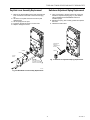
M12205
SPRING
LEVER
COVER
PLATE
CAUTION:
THIS PIN IS FREE
TO DROP OUT WHEN
LEVER IS RELEASED.
Day/Auto Lever Assembly Replacement
1. Remove the three Phillips head screws that fasten the
lever mechanism to the back of the thermostat (Fig.
20).
2. Lift off the cover plate and remove the lever (with
attached seal).
3. Lift the spring from the post.
4. Install the replacement parts in reverse order.
5. Replace and tighten screws.
M12137
14001992-001
16/21 PSI
CHANGEOVER
SPRING
SCREW
Fig. 20. DAY/AUTO Lever Assembly Replacement.
Switchover Adjustment Spring Replacement
1. Using a screwdriver, carefully remove the screw and
switchover adjustment spring (Fig. 21). See PARTS
LIST in PARTS and ACCESSORIES section for
available springs.
2. Replace the spring, then carefully position and replace
the screw.
3. Calibrate the thermostat.
Fig. 21. Switchover Adjustment Spring Replacement.

18
TP970 AND TP9600 SERIES PNEUMATIC THERMOSTATS
75-7134—1
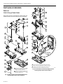
PARTS AND ACCESSORIES
Parts List
TP970-TP974 and TP9600-TP9630
See Figures 22 and 23, and Table 8 for TP970-TP974 and
TP9600-TP9630 Thermostat repair parts and assemblies.
1
6
1A
1B
1C
1D
7
8
9
10B
10
*
10C
10D
11
12
2
1
M12210
2
REPLACE THE SETPOINT CAM ASSEMBLY AND NOZZLE,
THROTTLING PLATE, AND BIMETAL ASSEMBLY TOGETHER.
IF THERE IS NO ANTIHUM SPRING/CONE, THERE IS AN
ADHESIVE PAPER DOT ON THE THROTTLING PLATE.
1
1
2
10F
10E
10
*
BOTTOM VIEW
OF
1
5
6
6
10A
1A
1B
1C
1D
7
8
9
10
10B
10
10C
10D
11
12
2
3
4
1
M12209
2
REPLACE THE SETPOINT CAM ASSEMBLY
AND NOZZLE, THROTTLING PLATE, AND
BIMETAL ASSEMBLY TOGETHER.
IF THERE IS NO ANTIHUM SPRING/CONE,
THERE IS AN ADHESIVE PAPER DOT ON
THE THROTTLING PLATE.
1
1
1
2
Fig. 22. Single Element Thermostat Exploded View
Showing Repair Parts and Assemblies.
Fig. 23. Dual Element Thermostat Exploded View
Showing Repair Parts and Assemblies.

TP970 AND TP9600 SERIES PNEUMATIC THERMOSTATS
19
75-7134—1
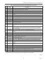
Table 8. TP970-TP974 and TP9600-TP9630 Thermostat Repair Parts and Assemblies.
Key
No. Part No. Description
1 14004459-001 Scaleplate Bag Assembly (60 to 90F) - TP970A-D, TP973A, B
14004459-002 Scaleplate Bag Assembly (40 to 70F) - TP970A-D
14004459-003 Scaleplate Bag Assembly (15 to 30C) - TP970A-D, TP973A, B
14004459-004 Scaleplate Bag Assembly (60 to 90F) - TP971A-E
14004459-005 Scaleplate Bag Assembly (15 to 30C) - TP971A-C
1A — Pointer
1B — Thermostat Assembly
1C — Scaleplate
1D — Thermostat Mounting Post
2 — Retainer Ring (Fig. 23)
2 — Washer (Fig. 24)
3 — Scaleplate
4 — Post, Thermostat Assembly
5 — Bushing - TP973
* 14004447-001 Setpoint Cam Assembly - TP970A1004, A1012, A1020, A1038, A1046, A1053, A1095, A2004,
A2012, A2020, A2038, A2053, A2095; TP970C; TP972A1143, A2143; TP973A1001, A1019,
A1127
14004447-002 Setpoint Cam Assembly - TP970B1002, B1010, B1028, B1036, B2002, B2010, B2028, B2036;
TP970D; TP972A1002, A1010, A1028, A1044, A2002, A2010, A2028, A2044; TP973B1009,
B1017, B1025, B1108
14004447-003 Setpoint Cam Assembly - TP971A, C, D; TP972A1168, A2168, A2176
14004447-004 Setpoint Cam Assembly - TP971B, E; TP972A1036, A1077, A1085, A1150, A1184, A2036,
A2150
14004447-005 Setpoint Cam Assembly - TP970B1044; TP972A1051, A1101
14004447-006 Setpoint Cam Assembly - TP970A1061, A1087, A2087
14004447-007 Setpoint Cam Assembly - TP972A1093, A1127
14004447-008 Setpoint Cam Assembly - TP972A 1119
14004429-001 Setpoint Cam - TP973A1035, A1043, A1050, A1068, A1076, A1084, A1092, A1100, A2068,
A2076, A2084, A2092, A2100
14004429-002 Setpoint Cam - TP973B1033, B1041, B1058, B1066, B1074, B1090, B2066, B2074, B2090
7 — Screw, No. 4-3/16 pan head
8* 14004460-001 Nozzle, Throttling Plate, Bimetal Assembly, DA, Left Side - TP970A; TP971A, C, D; TP972A;
TP973A
14004460-002 Nozzle, Throttling Plate, Bimetal Assembly, RA Left Side - TP970B; TP971B, E; TP972A;
TP973B
14004460-003 Nozzle, Throttling Plate, Bimetal Assembly, DA, Right Side - TP971A, C; TP972A
14004460-004 Nozzle, Throttling Plate, Bimetal Assembly, DA - TP970C
14004460-005 Nozzle, Throttling Plate, Bimetal Assembly, RA - TP970D
14004460-006 Nozzle, Throttling Plate, Bimetal Assembly, DA, Right Side - TP971D
14004460-007 Nozzle, Throttling Plate, Bimetal Assembly, RA, Right Side - TP971E
9† — Antihum Spring/Cone
*Replace the Setpoint Cam Assembly and Nozzle, Throttling Plate, Bimetal Assembly together.
†If there is no antihum spring or cone, there is an adhesive paper dot on the throttling plate.
(continued)

20
TP970 AND TP9600 SERIES PNEUMATIC THERMOSTATS
75-7134—1
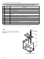
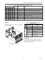
TP978E
See Figure 24 and Table 9 for TP978E Thermostat repair
parts and assemblies. The TP978A-D Thermostats have not
been replaced.
5
4
3
2
1
M12207
Fig. 24. TP978E Exploded View.
Key
No. Part No. Description
10 14002051-001 Pneumatic Assembly, TP970-TP973 - Includes 10B and 10C below
14002102-004 Pneumatic Assembly, TP974A - Includes 10B and 10C below
10A — Tab and Screw - TP974A
10B 14004419-001 Gasket, Restrictor block (included with 14002374-XXX)
10C 14001865-001 Filter
10D 14002374-001 Restrictor Block Assembly (0.005 restrictor, 2 pipe) - TP970A-D; TP971A, B, D, E; TP972A;
TP973A, B
14002374-005 Restrictor Block Assembly (0.005 restrictor, 3 pipe) - TP971C
14002374-006 Restrictor Block Assembly (0.007 restrictor, 2 pipe) - TP974A
10E 14002373-001 Switchover Spring Assembly, silver - 16 to 21 psi (110 to 145 kPa)
14002373-002 Switchover Spring Assembly, gold - 13 to 18 psi (90 to 124 kPa)
14003923-001 Switchover Spring Assembly, blue - 20 to 25 psi (140 to 175 kPa)
10F 14002372-001 DAY/AUTO Lever Assembly
11 — Screw, No. 4-40 x 5/8 an head (included with 14002374-XXX)
12 14002053-001 Wall Plate Assembly with setscrews 14003454-001 (2)
*Replace the Setpoint Cam Assembly and Nozzle, Throttling Plate, Bimetal Assembly together.
†If there is no antihum spring or cone, there is an adhesive paper dot on the throttling plate.
Table 8. TP970-TP974 and TP9600-TP9630 Thermostat Repair Parts and Assemblies (continued).
Page is loading ...
Page is loading ...
Page is loading ...
Page is loading ...
-
 1
1
-
 2
2
-
 3
3
-
 4
4
-
 5
5
-
 6
6
-
 7
7
-
 8
8
-
 9
9
-
 10
10
-
 11
11
-
 12
12
-
 13
13
-
 14
14
-
 15
15
-
 16
16
-
 17
17
-
 18
18
-
 19
19
-
 20
20
-
 21
21
-
 22
22
-
 23
23
-
 24
24


Ask a question and I''ll find the answer in the document
Finding information in a document is now easier with AI
Related papers
-
Honeywell CT50A User manual
-
Honeywell R841E User manual
-
-
-
-
Honeywell T104F User manual
-
-
Honeywell C User manual
-
-
Other documents
-
Broan AE80S Installation guide
-
Siemens RC 195 Installation guide
-
-
LADEN EV 1044 User guide
-
-
ZEBRONICS Zeb-Action Wireless 10W Portable Speaker User manual
-
-
White Rodgers 1A10 User manual
-
Powers 900 Installation guide
-