Page is loading ...

Multi-Position, Modulating
Variable-sPeed gas Furnace
uP
to 96% aFue
Contents
Nomenclature .................................................................... 2
Product Specications .......................................................3
Dimensions ........................................................................4
Airow Data .......................................................................6
Wiring Diagrams ..............................................................11
Thermostats ....................................................................12
Accessories .......................................................................12
* Complete warranty details available from your local dealer or at www.goodmanmfg.com. To receive the Lifetime Heat Exchanger Limited Warranty (good
for as long as you own your home), 10-Year Unit Replacement Limited Warranty and 10-Year Parts Limited Warranty, online registration must be completed
within 60 days of installation. Online registration is not required in California or Québec.
Standard Features
• Aluminized-steel, dual-diameter tubular heat exchanger
• Stainless-steel secondary heat exchanger
• Up to 96% AFUE
• ComfortNet
TM
Communicating Systems compatible
• Self-calibrating, modulating gas valve operates with two-
stage or single-stage thermostats
• Efcient and quiet variable-speed circulator motor gently
ramps up or down according to heating or cooling demand
• Durable Silicon Nitride igniter
• Furnace control board with self-diagnostics, color-coded
low-voltage terminals and provisions for electronic air
cleaners and humidiers
• Low constant fan speed allows homeowner to quietly circu-
late air throughout the home. This setting costs as little as a
100-watt light bulb to operate.
• Dual-certied for sealed combustion direct vent (2-pipe) or
non-direct vent (1-pipe) applications
• Auto-Comfort and enhanced dehumidication modes
provide energy savings and additional comfort during the
cooling months
• Easy-to-install top venting is standard; alternate ue/vent
located on right
• Quiet two-speed induced draft blower
• All models comply with California NOx emissions standards
Cabinet Features
• Fully insulated heavy-gauge steel cabinet with durable baked-
enamel nish
• Foil-faced insulation lines the heat exchanger section
• Designed for multi-position installation: upow, horizontal
left, or right
• Airtight solid bottom for side-return applications and easy-cut
tabs for effortless removal in bottom air-inlet applications
• Convenient left or right connection for gas and electric service
• Coil and furnace t ush for most installations
SS-GMVM96 www.goodmanmfg.com 6/11
gMVM96
& gcVM96

PRoDucT sPeciFicATions
PRoDucT sPeciFicATions
2 www.goodmanmfg.com SS-GMVM96
noMenclATuRe
G
Goodman
®
Brandor
A Ini.alReleases(Major&Minor)
Dis.nc.ons™ B 1stRevisions(Major&Minor)
C 2ndRevisions
C
Downflow/Horizontal
D DedicatedDownflow N NaturalGas
H HighAirflow X LowNOx
K DedicatedUpflow
M Upflow/Horizontal
A14”
B17½”
V TwoStage/Variablespeed C21”
H TwoStage/Mul.speed D24½”
S SingleStage/Mul.speed
E TwoStage/HighEfficiency
31200
41600
C ComfortNet™Communica.ngSystem 52000
M Modula.ngFurnace
045:45,000
060:60,000
96 96% 9
90%+
080:80,000
95 95% 8 80% 100:100,000
115:115,000
Important EnergyStar Notice: EnergyStar ratings are dependent upon conditions beyond
equipment installation. Proper sizing and installation of equipment is critical to
achieve optimal performance. Split system air conditioners and heat pumps must
be matched with appropriate coil components to meet EnergyStar criteria. Ask your
contractor for details or visit www.energystar.gov.

PRoDucT sPeciFicATions
PRoDucT sPeciFicATions
SS-GMVM96 www.goodmanmfg.com 3
sPeciFicATions
GMVM96
0603BX
GMVM96
0805CX
GMVM96
1005DX
GMVM96
1155DX
GCVM96
0604CX
GCVM96
0805DX
GCVM96
1005DX
High Fire Input¹ 60,000 80,000 100,000 115,000 60,000 80,000 100,000
High Fire Output¹ 57,600 76,800 96,000 109,250 57,600 76,800 95,000
Low-Fire Steady-State Input¹ 30,000 40,000 50,000 57,500 30,000 40,000 50,000
Low-Fire Steady-State Output¹ 28,800 38,400 48,000 54,625 28,800 38,400 47,500
AFUE² 96 96 96 95 96 96 95
Tons AC @ 0.5” ESP 1.5-3.0 2.0-5.0 2.0-5.0 2.0-5.0 1.5-4.0 2.0-5.0 2.0-5.0
Temperature Rise Range (°F) 20-50 35-65 35-65 35-65 20-50 20-50 25-55
Size (D x W) 10" X 8" 11" X 10" 11" X 10" 11" X 10" 10"X 10" 11" X 10" 11" X 10"
Horespower @ 1050 RPM 3/4 1 1 1 3/4 1 1
Speed Variable Variable Variable Variable Variable Variable Variable
Vent Diameter³ 2" 3" 3" 3" 2" 3" 3"
No. of Burners 3 4 5 5 3 4 5
Disposable Filter (in²) 576 960 960 972 641 854 854
Min. Circuit Ampacity (amps)⁴ 6.0 14.2 14.2 14.2 6.0 14.2 14.2
Max. Overcurrent Protecon⁵ 15.0 15.0 15.0 15.0 15.0 15.0 15.0
135 145 170 170 139 165 170
¹ Natural Gas BTU/h
² DOE AFUE based upon Isolated Combuson System (ICS)
³ Installer must supply one or two PVC pipes: one for combuson air (oponal) and one for the ue outlet (required). Vent pipe must be either 2” or 3” in
diameter, depending upon furnace input, number of elbows, length of run and installaon (1 or 2 pipes). The oponal Combuson Air Pipe is dependent
on installaon/code requirements and must be 2” or 3” diameter PVC.
⁴ Minimum Circuit Ampacity = (1.25 x Circulator Blower Amps) + ID Blower amps. Wire size should be determined in accordance with Naonal Electrical
Codes. Extensive wire runs will require larger wire sizes.
⁵ Maximum Overcurrent Protecon Device refers to maximum recommended fuse or circuit breaker size. May use fuses or HACR-type circuit breakers of
the same size as noted.
• All furnaces are manufactured for use on 115 VAC, 60 Hz, single-phase electrical supply.
• Gas Service Connecon ½” FPT
• Important: Size fuses and wires properly and make electrical connecons in accordance with the Naonal Electrical Code and/or all exisng local codes.

PRoDucT sPeciFicATions
PRoDucT sPeciFicATions
4 www.goodmanmfg.com SS-GMVM96
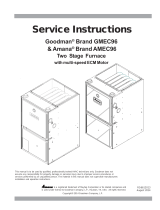
gMVM96 DiMensions
MiniMuM cleARAnces To coMbusTible MATeRiAls
Upow 0” 0” 3” C 0” 1”
Horizontal 6” 0” 3” C 0” 6”
C = If placed on combusble oor, the oor MUST be wood ONLY.
• For servicing or cleaning, a 24” front clearance is required.
• Unit connecons (electrical, ue and drain) may necessitate greater clearances than the minimum clearances listed above.
• In all cases, accessibility clearance must take precedence over clearances from the enclosure where accessibility clearances are greater.
28¾
19⅞
RIGHT SIDE VIEW
LEFT SIDE VIEW
22 ¹/₁₁
FOLDED FLANGES
23 ⁹/₁₆
UNFOLDED FLANGES
FRONT VIEW
FOLDED FLANGES
UNFOLDED FLANGES
D
E
1¾
11¾
30¼
¾
¾
30¼
1¾
11¾
1¾
32¹³/₁₁
19³/₁₁
24₁/₁₁
2¹¹/₁₁
2¹/₁₁
19³/₁₁
¾
1½
21¼
2⅝
7⅜
1⅝
2½
4⅛
16⅝
2⅝
27⅛
6⅛
D H A B C D E
GMVM960603BX 17½” 28¾" 40¾" 17½” 16" 13⅛" 12⅛" 13⅝"
GMVM960805CX 21" 28¾" 40¾" 21" 19½” 16⅛" 16" 17½”
GMVM961005DX 24½” 28¾" 40¾" 24½” 23" 20⅝" 19⅜" 20⅞"
GMVM961155DX 24½” 28¾" 40¾" 24½” 23" 20⅝" 19⅜" 20⅞"
• Installer must supply one or two PVC pipes: one for combuson air (oponal) and one for the ue outlet (required). Vent pipe must be either 2” or 3”
in diameter, depending upon furnace input, number of elbows, length of run and installaon
(1 or 2 pipes). The oponal Combuson Air Pipe is dependent on installaon/code requirements and must be 2” or 3” diameter PVC.
• Line voltage wiring can enter through the right or le side of the furnace. Low-voltage wiring can enter through the right or le side of furnace.
• Conversion kits for high-altude natural gas operaon are available. Contact your Goodman distributor or dealer for details.
• Installer must supply following gas line ngs, according to which entrance is used:
Le—Two 90º elbows, one close nipple, straight pipe
Right—Straight pipe to reach gas valve
• For boom return: Failure to unfold anges may reduce airow by up to 18%. This could result in performance and noise issues.

PRoDucT sPeciFicATions
PRoDucT sPeciFicATions
SS-GMVM96 www.goodmanmfg.com 5
gcVM96 DiMensions
FOLDED FLANGES
UNFOLDED FLANGES
FOLDED FLANGES
UNFOLDED FLANGES
MiniMuM cleARAnces To coMbusTible MATeRiAls
Downow 0” 0” 3” NC 0” 1”
Horizontal 6” 0” 3” C 0” 6”
C = If placed on combusble oor, the oor MUST be wood ONLY.
NC = For installaon on non-combusble oors only. A combusble oor sub-base must be used for installaons on combusble ooring.
• For servicing or cleaning, a 24” front clearance is required.
• Unit connecons (electrical, ue and drain) may necessitate greater clearances than the minimum clearances listed above.
• In all cases, accessibility clearance must take precedence over clearances from the enclosure where accessibility clearances are greater.
D H A B C D E
GCVM960604CX 21" 28¾" 40¾" 21" 19½” 16⅛" 18" 19½”
GCVM960805DX 24½” 28¾" 40¾" 24½” 23" 20⅝" 21½” 23"
GCVM961005DX 24½” 28¾" 40¾" 24½” 23" 20⅝" 21½” 23"
• Installer must supply one or two PVC pipes: one for combuson air (oponal) and one for the ue outlet (required). Vent pipe must be either 2” or
3” in diameter, depending upon furnace input, number of elbows, length of run, and installaon (1 or 2 pipes). The oponal Combuson Air Pipe is
dependent on installaon/code requirements and must be 2” or 3” diameter PVC.
• Line voltage wiring can enter through the right or le side of the furnace. Low-voltage wiring can enter through the right or le side of furnace.
• Conversion kits for high-altude natural gas operaon are available. Contact your Goodman distributor or dealer for details.
• Installer must supply following gas line ngs, according to which entrance is used:
Le—Two 90º elbows, one close nipple, straight pipe
Right—Straight pipe to reach gas valve
• For boom return: Failure to unfold anges may reduce airow by up to 18%. This could result in performance and noise issues.

PRoDucT sPeciFicATions
PRoDucT sPeciFicATions
6 www.goodmanmfg.com SS-GMVM96
gMVM96 AiRFlow DATA — cooling sPeeDs
GMVM960603BX GVMV960805CX
CFM* CFM* CFM* CFM*
A
Minus(-) 567
A
Minus(-) 351
A
Minus(-) 747
A
Minus(-) 486
Normal 630 Normal 390 Normal 830 Normal 540
Plus (+) 693 Plus (+) 429 Plus (+) 913 Plus (+) 594
B
Minus(-) 720
B
Minus(-) 495
B
Minus(-) 981
B
Minus(-) 675
Normal 800 Normal 550 Normal 1090 Normal 750
Plus (+) 880 Plus (+) 605 Plus (+) 1199 Plus (+) 825
C
Minus(-) 900
C
Minus(-) 612
C
Minus(-) 1314
C
Minus(-) 882
Normal 1000 Normal 680 Normal 1460 Normal 980
Plus (+) 1100 Plus (+) 748 Plus (+) 1606 Plus (+) 1078
D
Minus(-) 1089
D
Minus(-) 720
D
Minus(-) 1620
D
Minus(-) 1089
Normal 1210 Normal 800 Normal 1800 Normal 1210
Plus (+) 1331 Plus (+) 880 Plus (+) 1980 Plus (+) 1331
* @ .1" - .8" w.c. ESP * @ .1" - .8" w.c. ESP
GMVM961005DX GMVM961155DX
CFM* CFM* CFM* CFM*
A
Minus(-) 711
A
Minus(-) 459
A
Minus(-) 711
A
Minus(-) 459
Normal 790 Normal 510 Normal 790 Normal 510
Plus (+) 869 Plus (+) 561 Plus (+) 869 Plus (+) 561
B
Minus(-) 990
B
Minus(-) 639
B
Minus(-) 990
B
Minus(-) 639
Normal 1100 Normal 710 Normal 1100 Normal 710
Plus (+) 1210 Plus (+) 781 Plus (+) 1210 Plus (+) 781
C
Minus(-) 1269
C
Minus(-) 819
C
Minus(-) 1269
C
Minus(-) 819
Normal 1410 Normal 910 Normal 1410 Normal 910
Plus (+) 1551 Plus (+) 1001 Plus (+) 1551 Plus (+) 1001
D
Minus(-) 1647
D
Minus(-) 1044
D
Minus(-) 1647
D
Minus(-) 1044
Normal 1830 Normal 1160 Normal 1830 Normal 1160
Plus (+) 2013 Plus (+) 1276 Plus (+) 2013 Plus (+) 1276
* @ .1" - .8" w.c. ESP
• All furnaces ship as high speed for cooling. Installer must adjust blower speed as needed.
• For most jobs, about 400 CFM per ton when cooling is desirable.
• Operaon is recommended below .5” w.c. ESP in heang mode. Operang CFM between .5” and .8” w.c. is tabulated for cooling purposes only.

PRoDucT sPeciFicATions
PRoDucT sPeciFicATions
SS-GMVM96 www.goodmanmfg.com 7
gMVM96 AiRFlow DATA — HeATing sPeeDs
GMVM960603BX
GMVM960805CX
Minus(-) 855 62 Minus(-) 1,440 49
Normal 950 56 Normal 1,600 44
Plus (+) 1,045 51 Plus (+) 1,760 40
Minus(-) 945 56 Minus(-) 1,521 47
Normal 1,050 51 Normal 1,690 42
Plus (+) 1,155 46 Plus (+) 1,859 38
Minus(-) 1,053 50 Minus(-) 1,620 44
Normal 1,170 45 Normal 1,800 39
Plus (+) 1,287 41 Plus (+) 1,980 36
Minus(-) 1,143 46 Minus(-) 1,701 42
Normal 1,270 42 Normal 1,890 37
Plus (+) 1,397 38 Plus (+) 2,079 34
* @ .1" - .5" w.c. ESP * @ .1" - .5" w.c. ESP
GMVM961005DX
GMVM961155DX
Minus(-) 1,629 54 Minus(-) 1,629 62
Normal 1,810 49 Normal 1,810 56
Plus (+) 1,991 44 Plus (+) 1,991 51
Minus(-) 1,665 53 Minus(-) 1,665 60
Normal 1,850 48 Normal 1,850 54
Plus (+) 2,035 43 Plus (+) 2,035 49
Minus(-) 1,701 52 Minus(-) 1,701 59
Normal 1,890 47 Normal 1,890 53
Plus (+) 2,079 43 Plus (+) 2,079 48
Minus(-) 1,746 51 Minus(-) 1,746 58
Normal 1,940 46 Normal 1,940 52
Plus (+) 2,134 41 Plus (+) 2,134 47
* @ .1" - .5" w.c. ESP * @ .1" - .5" w.c. ESP
• All furnaces ship as high speed for cooling. Installer must adjust blower speed as needed.
• For most jobs, about 400 CFM per ton when cooling is desirable.
• Operaon is recommended below .5” w.c. ESP in heang mode. Operang CFM between .5” and .8” w.c. is tabulated for
cooling purposes only.
• 100% CFM shown. CFM will vary proporonally with the gas valve BTU/H input.

PRoDucT sPeciFicATions
PRoDucT sPeciFicATions
8 www.goodmanmfg.com SS-GMVM96
gcVM96 AiRFlow DATA — cooling sPeeDs
GCVM960604CX GCVM960805DX
A
Minus(-) 594
A
Minus(-) 333
A
Minus(-) 810
A
Minus(-) 477
Normal 660 Normal 370 Normal 900 Normal 530
Plus (+) 726 Plus (+) 407 Plus (+) 990 Plus (+) 583
B
Minus(-) 774
B
Minus(-) 486
B
Minus(-) 990
B
Minus(-) 657
Normal 860 Normal 540 Normal 1100 Normal 730
Plus (+) 946 Plus (+) 594 Plus (+) 1210 Plus (+) 803
C
Minus(-) 1035
C
Minus(-) 711
C
Minus(-) 1287
C
Minus(-) 837
Normal 1150 Normal 790 Normal 1430 Normal 930
Plus (+) 1265 Plus (+) 869 Plus (+) 1573 Plus (+) 1023
D
Minus(-) 1323
D
Minus(-) 882
D
Minus(-) 1692
D
Minus(-) 1098
Normal 1470 Normal 980 Normal 1880 Normal 1220
Plus (+) 1617 Plus (+) 1078 Plus (+) 2068 Plus (+) 1342
* @ .1” - .8” w.c. ESP
• All furnaces ship as high speed for cooling. Installer must adjust blower speed as needed.
• For most jobs, about 400 CFM per ton when cooling is desirable.
• Operaon is recommended below .5” w.c. ESP in heang mode. Operang CFM between .5” and .8” w.c. is tabulated for cooling purposes only.
GCVM961005DX
A
Minus(-) 702
A
Minus(-) 450
Normal 780 Normal 500
Plus (+) 858 Plus (+) 550
B
Minus(-) 963
B
Minus(-) 666
Normal 1070 Normal 740
Plus (+) 1177 Plus (+) 814
C
Minus(-) 1242
C
Minus(-) 828
Normal 1380 Normal 920
Plus (+) 1518 Plus (+) 1012
D
Minus(-) 1602
D
Minus(-) 1044
Normal 1780 Normal 1160
Plus (+) 1958 Plus (+) 1276
* @ .1” - .8” w.c. ESP
• All furnaces ship as high speed for cooling. Installer must adjust blower speed as needed.
• For most jobs, about 400 CFM per ton when cooling is desirable.
• Operaon is recommended below .5” w.c. ESP in heang mode. Operang CFM between .5” and .8” w.c. is tabulated for cooling purposes only.

PRoDucT sPeciFicATions
PRoDucT sPeciFicATions
SS-GMVM96 www.goodmanmfg.com 9
gcVM96 AiRFlow DATA — HeATing sPeeDs
GCVM960604CX
ACVM960604CX
GCVM960805DX
ACVM960805DX
Minus(-) 1,098 48 Minus(-) 1,440 49
Normal 1,220 44 Normal 1,600 44
Plus (+) 1,342 40 Plus (+) 1,760 40
Minus(-) 1,206 44 Minus(-) 1,539 46
Normal 1,340 40 Normal 1,710 41
Plus (+) 1,474 36 Plus (+) 1,881 38
Minus(-) 1,314 40 Minus(-) 1,620 44
Normal 1,460 36 Normal 1,800 39
Plus (+) 1,606 33 Plus (+) 1,980 36
Minus(-) 1,431 37 Minus(-) 1,719 41
Normal 1,590 33 Normal 1,910 37
Plus (+) 1,749 30 Plus (+) 2,101 34
* @ .1" - .5" w.c. ESP * @ .1" - .5" w.c. ESP
GCVM961005DX
Minus(-) 1,557 56
Normal 1,730 51
Plus (+) 1,903 46
Minus(-) 1,593 55
Normal 1,770 49
Plus (+) 1,947 45
Minus(-) 1,656 53
Normal 1,840 48
Plus (+) 2,024 43
Minus(-) 1,683 52
Normal 1,870 47
Plus (+) 2,057 43
* @ .1" - .5" w.c. ESP
• All furnaces ship as high speed for cooling. Installer must adjust blower speed as needed.
• For most jobs, about 400 CFM per ton when cooling is desirable.
• Operaon is recommended below .5” w.c. ESP in heang mode. Operang CFM between .5” and .8” w.c. is tabulated for
cooling purposes only.
• 100% CFM shown. CFM will vary proporonally with the gas valve BTU/H input.

PRoDucT sPeciFicATions
PRoDucT sPeciFicATions
10 www.goodmanmfg.com SS-GMVM96
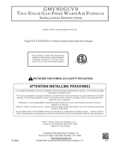
TeMPeRATuRe Rise RAnge cHART
BLOWER PERFORMANCE SPECIFICATIONS
14
30 40 50 60 70 80 90 110 120
100
130 140 150
100
90
80
70
60
50
40
30
20
10
OUTPUT BTU/HR x 1000
BTU OUTPUT vs TEMPERATURE RISE CHART
TEMPERATURE RISE
600 CFM
700
900
1000
1100
1200
1400
1600
1800
2000
2200
2400 CFM
FORMULAS
BTU OUTPUT = CFM x 1.08 x RISE
RISE =
BTU OUTPUT
1.08
÷ CFM
800

PRoDucT sPeciFicATions
PRoDucT sPeciFicATions
SS-GMVM96 www.goodmanmfg.com 11
wiRing DiAgRAM
Wiring is subject to change. Always
refer to the wiring diagram or the
unit for the most up-to-date wiring.
⚠
Warning
Disconnect all power before servicing or installing this unit. Mulple power
sources may be present. Failure to do so may cause property damage, personal injury, or death.
⚡
OPTIONAL
OPTIONAL
OPTIONAL
TR (9)
PRESS. SWITCH
FRONT COVER
L
I
M
I
T
C
O
N
T
R
O
L
S
M
A
N
U
A
L
R
E
S
E
T
R
O
L
L
O
U
T
P
R
E
S
S
.
S
W
I
T
C
H
L
O
W
F
I
R
E
P
R
E
S
S
.
L
I
M
I
T
C
O
N
T
R
O
L
A
U
T
O
R
E
S
E
T
P
R
IM
A
R
Y
A
U
T
O
R
E
S
E
T
A
U
X
I
L
IA
R
Y
L
I
M
I
T
2
4
V
A
C
T
O
+
V
D
C
T
R
(
5
)
F
U
S
E
3
A
4
0
V
A
H
O
T
S
U
R
F
A
C
E
3
Ø
I
D
INTEGRATED CONTROL MODULE
A
I
R
C
L
E
A
N
E
R
1
1
5
k
B
T
U
M
O
D
E
L
S
POLARIZED AND
MUST BE PROPERLY
WIRING TO UNIT
BEFORE SERVICING
DISCONNECT POWER
OVERCURRENT PROTECTION DEVICE
Ø /60 HZ POWER SUPPLY WITHTO 115VAC/1
S
W
IT
C
H
A
S
S
E
M
B
L
Y
I
D
B
L
O
W
E
R
T
W
O
-
S
T
A
G
E
P
R
E
S
S
U
R
E
S
W
IT
C
H
L
O
W
F
I
R
E
(
H
O
N
E
Y
W
E
L
L
)
G
A
S
V
A
L
V
E
2
C
I
R
C
U
IT
P
R
E
S
S
U
R
E
S
W
I
T
C
H
F
R
O
N
T
C
O
V
E
R
(
S
IN
G
L
E
C
O
N
T
R
O
L
O
N
4
5
k
B
T
U
)
M
A
N
U
A
L
R
E
S
E
T
R
O
L
L
O
U
T
L
I
M
I
T
C
O
N
T
R
O
L
S
L
IM
I
T
C
O
N
T
R
O
L
A
U
T
O
R
E
S
E
T
P
R
I
M
A
R
Y
B
U
R
N
E
R
C
O
M
P
A
R
T
M
E
N
T
B
L
O
W
E
R
C
O
M
P
A
R
T
M
E
N
T
A
U
T
O
R
E
S
E
T
L
I
M
I
T
C
O
N
T
R
O
L
FURNACE CONTROL MODULE
MODULATING INTERGRATED
COOL TAPS
HEAT TAPS
FAN TAPS
DIP SWITCHES
HEAT OFF
HEAT SETUP
COOL SETUP
PULL UP
PULL DOWN
2
4
V
T
H
E
R
M
O
S
T
A
T
C
O
N
N
E
C
T
I
O
N
S
24V HUM.
INTEGRATED CONTROL MODULE
24V THERMOSTAT CONNECTIONS
1
1
5
k
B
T
U
M
O
D
E
L
S
(
O
P
E
N
W
H
E
N
D
O
O
R
S
W
I
T
C
H
2
4
V
3
A
E
C
M
M
T
R
IN
S
T
A
N
D
B
Y
(
N
O
T
H
E
R
M
O
S
T
A
T
I
N
P
U
T
S
)
R
E
C
E
N
T
,
D
E
P
R
E
S
S
S
W
IT
C
H
F
O
R
M
O
R
E
T
H
A
N
2
S
E
C
O
N
D
S
W
H
I
L
E
5
.
T
O
R
E
C
A
L
L
T
H
E
L
A
S
T
1
0
F
A
U
L
T
S
,
M
O
S
T
R
E
C
E
N
T
T
O
L
E
A
S
T
N
.E
.C
.
A
N
D
L
O
C
A
L
C
O
D
E
S
.
4
.
U
N
IT
M
U
S
T
B
E
P
E
R
M
A
N
E
N
T
L
Y
G
R
O
U
N
D
E
D
A
N
D
C
O
N
F
O
R
M
T
O
L
E
A
S
T
1
0
5
°
C
.
U
S
E
C
O
P
P
E
R
C
O
N
D
U
C
T
O
R
S
O
N
L
Y
.
W
I
R
I
N
G
M
A
T
E
R
I
A
L
H
A
V
IN
G
A
T
E
M
P
E
R
A
T
U
R
E
R
A
T
I
N
G
O
F
A
T
F
U
R
N
A
C
E
M
U
S
T
B
E
R
E
P
L
A
C
E
D
,
I
T
M
U
S
T
B
E
R
E
P
L
A
C
E
D
W
I
T
H
3
.
I
F
A
N
Y
O
F
T
H
E
O
R
IG
I
N
A
L
W
I
R
E
A
S
S
U
P
P
L
I
E
D
W
I
T
H
T
H
E
U
S
E
D
W
H
E
N
S
E
R
V
I
C
I
N
G
.
2
.
M
A
N
U
F
A
C
T
U
R
E
R
'S
S
P
E
C
I
F
I
E
D
R
E
P
L
A
C
E
M
E
N
T
P
A
R
T
S
M
U
S
T
B
E
1
.
S
E
T
H
E
A
T
A
N
T
IC
I
P
A
T
O
R
O
N
R
O
O
M
T
H
E
R
M
O
S
T
A
T
A
T
0
.7
A
M
P
S
.
B
K
B
L
A
C
K
P
U
P
U
R
P
L
E
Y
L
Y
E
L
L
O
W
B
L
B
L
U
E
W
H
W
H
I
T
E
B
R
B
R
O
W
N
P
K
P
I
N
K
C
O
L
O
R
C
O
D
E
S
:
P
L
U
G
C
O
N
N
E
C
T
I
O
N
IN
T
E
G
R
A
T
E
D
C
O
N
T
R
O
L
I
N
T
E
R
N
A
L
T
O
H
I
V
O
L
T
A
G
E
F
I
E
L
D
H
I
V
O
L
T
A
G
E
(
1
1
5
V
)
L
O
W
V
O
L
T
A
G
E
(
2
4
V
)
L
O
W
V
O
L
T
A
G
E
F
I
E
L
D
P
R
O
T
.
D
E
V
I
C
E
S
W
I
T
C
H
P
R
E
S
S
U
R
E
S
W
IT
C
H
(
T
E
M
P
)
F
I
E
L
D
S
P
L
IC
E
E
Q
U
I
P
M
E
N
T
G
N
D
P
R
O
P
E
R
L
Y
P
O
L
A
R
I
Z
E
D
T
O
U
N
IT
M
U
S
T
B
E
S
E
R
V
I
C
I
N
G
W
I
R
I
N
G
.
P
O
W
E
R
B
E
F
O
R
E
P
O
W
E
R
S
U
P
P
L
Y
W
IT
H
1
1
5
V
A
C
/
1
H
Z
Ø
/6
0
T
O
M
I
C
R
O
T
O
R
G
N
D
(
4
)
+
V
D
C
(
1
)
R
X
(
2
)
T
X
(
3
)
C
I
R
C
U
L
A
T
O
R
I
N
D
O
O
R
A
I
R
B
L
W
R
R
D
G
Y
B
L
B
K
H
U
M
I
D
I
F
I
E
R
G
N
D
P
R
O
T
E
C
T
I
O
N
D
E
V
I
C
E
L
IN
E
RD
T
O
C
B
K
R
D
I
G
N
IT
E
R
F
L
A
M
E
S
E
N
S
O
R
I
N
T
E
G
R
A
T
E
D
C
O
N
T
R
O
L
M
O
D
U
L
E
OR
T
E
R
M
I
N
A
L
O
R
O
R
A
N
G
E
P
M
H
A
R
N
E
S
S
NO
(
1
2
)
3
C
C
I
R
C
U
L
A
T
O
R
B
K
BK
O
V
E
R
C
U
R
R
E
N
T
2
4
V
H
U
M
.
0140F00863-B
I
G
N
I
T
E
R
2
4
P
M
I
N
D
U
C
E
D
D
R
A
F
T
B
L
O
W
E
R
E
A
C
C
1
1
5
V
A
C
IN
D
U
C
T
O
R
C
O
I
L
C
P
U
Y
L
DEHUM
G
N
D
2
H
O
T
S
U
R
F
A
C
E
I
G
N
I
T
E
R
(
7
)
N
E
U
T
R
A
L
D
O
O
R
S
W
I
T
C
H
4
3
2
CHASSIS
GROUND
W
H
V
A
C
G
N
D
Y
L
C
O
N
N
E
C
T
O
R
H
U
M
O
V
E
R
C
U
R
R
E
N
T
(
6
)
O
N
L
Y
C
M
O
D
U
L
A
T
I
N
G
D
IS
C
O
N
N
E
C
T
H
I
G
H
F
I
R
E
I
N
D
O
O
R
H
U
M
I
D
I
F
I
E
R
N
1
C
O
N
T
R
O
L
S
O
R
J
U
N
C
T
I
O
N
B
L
W
R
C
I
R
C
U
L
A
T
O
R
B
L
O
W
E
R
R
1
G
N
D
J
U
N
C
T
I
O
N
B
O
X
N
E
U
T
R
A
L
B
L
O
W
E
R
C
O
M
P
A
R
T
M
E
N
T
D
O
O
R
O
P
E
N
)
C
L
I
N
E
B
K
4
N
E
U
T
R
A
L
C
F
S
2
D
I
S
C
O
N
N
E
C
T
PU
H
I
G
H
F
IR
E
P
R
E
S
S
U
R
E
S
W
I
T
C
H
O
N
L
Y
W
1
7
0
k
B
T
U
,
9
0
k
B
T
U
,
N
O
(
8
)
O
W
H
5
G
N
D
(
4
)
B
K
3
I
G
N
P
K
G
Y
(
3
)
7
0
k
B
T
U
,
9
0
k
B
T
U
,
N
O
T
E
S
:
P
U
L
A
I
R
W
H
Y
1
G
Y
G
R
A
Y
E
L
E
C
T
R
O
N
I
C
R
D
R
E
D
Y
2
O
R
N
E
U
T
R
A
L
1
(
1
1
)
W
H
S
W
I
T
C
H
N
O
WH
T
R
A
N
S
F
O
R
M
E
R
B
R
BL
GR
2
G
R
O
U
N
D
E
D
.
W
2
W
A
R
N
I
N
G
:
F
IE
L
D
G
N
D
W
H
1
1
5
N
E
U
T
R
A
L
B
L
W
R
JUNCTION BOX
G
N
D
1
A
N
D
G
R
O
U
N
D
E
D
.
RD
G
A
S
V
A
L
V
E
P
U
I
N
D
U
C
T
O
R
C
O
IL
C
1
V
A
C
G
C
G
R
G
R
G
R
E
E
N
F
L
A
M
E
S
E
N
S
O
R
(
2
)
P
R
E
S
S
U
R
E
1
L
BR
N
O
3
N
O
N
G
Y
O
R
T
O
M
I
C
R
O
W
A
R
N
I
N
G
:
D
I
S
C
O
N
N
E
C
T
P
K
A
U
X
I
L
I
A
R
Y
2
N
O
BL
GY
BK
RD
OR
BR
BK
WH
RD
OR
WH
WH
WH
WH
BK
YL
OR
BIAS
2
F
U
S
E
ADJUST
LINE
DEHUM
2
3
1
NEUTRAL
3
DELAY
1
FLAME
SENSOR
4
D
I
A
G
N
O
S
T
I
C
L
E
D
'S
O
G
ID BLOWER
CONNECTOR
Y2
HUM
E
A
C
W1
R
2
Y1
1
C
W2
DEHUM
10
6
3
4
5
2
7
11
1
12
8
9
H
S
I
A
U
X
OR
2
G
N
D
(
1
0
)
BR
O
R
BK
BR
40 VA
TRANSFORMER
GY
RAMPING
BL
GY

PRoDucT sPeciFicATions
PRoDucT sPeciFicATions
12 www.goodmanmfg.com SS-GMVM96
Goodman Manufacturing Company, L.P., reserves the right to discontinue, or change at any time, specications or designs without
notice or without incurring obligations. © 2011 • Goodman Manufacturing Company, L.P. • Houston, Texas • Printed in the USA.
AccessoRies
THeRMosTATs
GTS1175-2
GTS3275-2
GTS 4275-2
Touch-Screen Digital Thermostats
(See Amana Thermostat specication sheets for details.)
G2111-2
G3272-2
G3273-2
Touch-Screen Digital Thermostats
(See Amana Thermostat specication sheets for details.)
G1100-2
G2100-2
G1152-2
G2152-2
Programmable and Non-programmable Digital Thermostats
(See Amana Thermostat specication sheets for details.)
GMVM96
0603BX
GMVM96
0805CX
GMVM96
1005DX
GMVM96
1155DX
GCVM96
0604CX
GCVM96
0805DX
GCVM96
1005DX
LPKM0D060UF
LP Conversion Kits
√
LPKM0D080UF
√
LPKM0D100UF
√
LPKM0D115UF
√
LPKM0D060CF √
LPKM0D080CF
√
LPKM0D100CF
√
EFR01 External Filter Rack
√ √ √ √
√ √ √
DCVK-20 Horizontal/Vercal Concentric Vent Kit (2”)
√ √ √ --- √ --- ---
DCVK-30 Horizontal/Vercal Concentric Vent Kit (3”)
√ √ √ √ √
√ √
CFB21 Downow Floor Base
--- --- --- --- √ --- ---
CFB24 Downow Floor Base
--- --- --- --- --- √ √
017K00000S Flush-mount vent kit √ √ √ √ √ √ √
√ Indicates available for this model
• For installaon in Canada, gas furnaces are cered only to 4,500’.
/