Soundstream X3.60 User manual
- Category
- Car audio amplifiers
- Type
- User manual
This manual is also suitable for

X3.60 / X3.71


TABLE OF CONTENTS
TABLE OF CONTENTS
ADJUSTING & TUNING
14
BRIDGING TWO AMPLIFIERS
13
PLANNING & MOUNTING YOUR SYSTEM
11
WIRING DIAGRAM
12
CONTROLS & FUNCTIONS
FEATURES & SPECIFICATIONS
INTRODUCTION
2
5 ~ 10
3 ~ 4
TROUBLE SHOOTING
15

INTRODUCTION
Amplier's provide high-performance sound reinforcement for your
mobile audio equipment. The Multi-Mode bridging capabilities allow
exibility in hosting several dierent speaker congurations.
To achieve optimum performance, it is highly recommended that you read
this Owners Manual before beginning installation.
2
INTRODUCTION

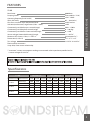
X3.60 16 Volts DC 14.4 Volts DC 12 Volts DC
Impedance Load Measurement
1 Ohm
2 Ohm
4 Ohm
RMS Wattage
RMS AC Volts
RMS Wattage
RMS AC Volts
RMS Wattage
RMS AC Volts
1% THD 1% THD 1% THD5% THD 5% THD 5% THD10% THD 10% THD 10% THD
2860 2940 3180 2780 2880 3115 2560 2635 2840
53.4 54.2 56.3 52.7 53.6 55.8 50.5 51.3 53.3
2070 2130 2300 1920 1988 2150 1344 1380 1490
64.3 65.3 67.8 61.9 63 65.6 51.8 52.5 54.5
1086 1120 1200 1050 1085 1178 898 925 998
65.9 66.9 69.3 64.8 65.8 68.6 59.9 60.8 63.1
FEATURES
Specications
* "maximum" current consumption reading was extracted at the impedance specied and at
a source voltage of 14.4V DC
4000Watts
350<@80Hz(+/- 5Hz)
15Hz ~150Hz
0.5 ~ 10.0 (volts)
24dB / octave
18dB
50Hz ~ 150Hz
0 ~ 180 deg.
0 ~ 18dB
11 ~ 16V DC
249 amperes DC *
21" x 11.5" x 2.5"
13.5V DC & 14.4V DC
Max Power
Damping factor
Operating frequency(band-width)
Input Sensitivity
Low-Pass crossover slope attenuation factor
Subsonic(cut/increase) range factor (15Hz ~ 40Hz)
Continuously variable low-pass control(range)
Continuously variable phase control(range)
Continuously variable bass boost control(range)
Source voltage (Automobile battery)(range)
Maximum DC current 1 Ohm, 1% THD +n
Dimensions(L x W x H)
Test voltage
Platinum RCA connectors
Strap-able; Slave-master relationship
Source voltage is limited to 11V~16V.
If source voltage beyond this limit is applied to the Amplier, the warranty will be voided.
X3.60
3
FEATURES & SPECIFICATIONS
4000 Watt 2-second Burp Power at 16V and 10%

FEATURES
a source voltage of 13.5V DC
6500Watts
350<@80Hz(+/- 5Hz)
15Hz ~150Hz
0.5 ~ 10.0 (volts)
24dB / octave
18dB
50Hz ~ 150Hz
0 ~ 180 deg.
0 ~ 18dB
11 ~ 16V DC
510 amperes DC *
23.75" x 11.5" x 2.5"
13.5V DC & 14.4V DC
Max Power
Damping factor
Operating frequency(band-width)
Input Sensitivity
Low-Pass crossover slope attenuation factor
Subsonic(cut/increase) range factor (15Hz ~ 40Hz)
Continuously variable low-pass control(range)
Continuously variable phase control(range)
Continuously variable bass boost control(range)
Source voltage (Automobile battery)(range)
Maximum DC current 1 Ohm, 1% THD +n
Dimensions(L x W x H)
Test voltage
Platinum RCA connectors
Strap-able; Slave-master relationship
Source voltage is limited to 11V~16V.
X3.71
4
CONTROLS & FUNCTIONS
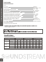
X3.71 16 Volts DC 14.4 Volts DC 12 Volts DC
Impedance Load Measurement
1 Ohm
2 Ohm
4 Ohm
RMS Wattage
RMS AC Volts
RMS Wattage
RMS AC Volts
RMS Wattage
RMS AC Volts
1% THD 1% THD 1% THD5% THD 5% THD 5% THD10% THD 10% THD 10% THD
4650 4780 5180 4450 4580 4960 3560 3670 3950
68.1 69.1 71.9 66.7 67.6 70.4 59.6 60.5 62.8
3400 3505 3780 3240 3330 3600 2310 2380 2570
82.5 83.7 86.9 80.5 81.6 84.8 67.9 69 71.7
1805 1860 2010 1750 1800 1945 1270 1305 1410
84.9 86.3 89.7 83.6 84.8 88.2 71.3 72.25 75.1
6500 Watt 2-second Burp Power at 16V and 10%

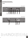
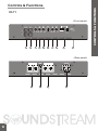
Controls & Functions
1 2 3 4 5 678 9
10
11
1213
14
X3.60
<Front panel>
<Rear panel>
CONTROLS & FUNCTIONS
5

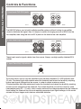
Controls & Functions
1 2 3 4 5 6 7 8 9 10
11
1213
14
X3.71
<Front panel>
<Rear panel>
CONTROLS & FUNCTIONS
6

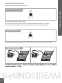
Controls & Functions
1.Low Level OUT RCA jacks
2. Low Level Input RCA jacks
The LINE OUT allows you to build multiple amplifier systems without having to use splitter
cords to distribute the signal. Now it is simply a matter of bringing one set of RCAS into the
first amplifier, then using the line out RCA jacks as the feed to the next amplifier.
These inputs are for signal cables from the source. Always use high quality shielded RCA
cables.
Min
Max
LEVEL
3. Input Sensitivity Adjustment
This control allows you to vary the amplifier's input sensitivity between 0.5 (500 millivolts) and
10 volts. Clockwise (right-side) rotation raises the threshold and lowers the sensitivity, requiring
higher input signal voltage from the source, in order to obtain maximum output.
Counterclockwise (left-side) adjustment lowers the threshold and raises the sensitivity, requiring
a lower source voltage from the headunit. The overall objective is to set this control to some
intermediate point (0.5 - 10 volts), which closely matches the voltage produced by the headunit.
Avoid setting the threshold too low and supplying excessive input signal voltage, as this would
saturate the input stages and introduce unwanted distortion.
LINE OUT LINE IN
L
R
CONTROLS & FUNCTIONS
LINE OUT LINE IN
R
L
LINE OUT LINE IN
L
R
LINE OUT LINE IN
R
L
X3.71 X3.60
7
X3.71 X3.60

Controls & Functions
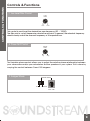
5. Bass Boost Control
4.Subsonic Filter Control
SUB
SONIC
15Hz
40Hz
Variable Subsonic Filter (15Hz - 40Hz) :
The Subsonic lter will roll o all of the unwanted frequencies below 15Hz - 40Hz.
This will allow the amplier to use that wasted power on the audible bandwidth.
By using the bass boost function, bass notes at 45Hz are emphasized as much as 18dB.
BASS
BOOST
0
+18dB
CONTROLS & FUNCTIONS
8
X3.71 X3.60

Controls & Functions
7. Low Level Filter Control
8. Phase Shift Control
9. Bridged Mode
LOW
PASS
50Hz 150Hz
This control is used to set the desired low pass frequency (50 ~ 150HZ).
The filter acts to cut-off frequencies above the set-point. In general, the selected frequency
should closely match the resonant frequency of the speaker box.
PHASE
SHIFT
0
0 0
180
0 0
The Variable phase control allows you to adjust the relative phase relationship between
your subwoofers and/or your subwoofers & other speakers in your system. This is done by
varying the control between 0 and 180 degrees.
DATA LINK
BRIDGED MODE
MASTERSLAVE
CONTROLS & FUNCTIONS
6
9

Controls & Functions
11. Power(Battery positive)
10. LED indicatior
PROTECTION
POWER
POWER : This GREEN LED will illuminate when the amplifier is turned "ON". If it fails to
illuminate, check the power connections to the Amplifier and fuses.
PROTECT: The amplifier protection circuitry will disable the amplifier if input overload, shor t
circuit or extremely high temperature conditions are detected. When the protection mode
is in operation, the red LED indicator on the side panel will be illuminated, indicating the
amplifier has gone into a self-preser vation mode.
If you observe that the Protection LED is lit, please check the system carefully to determine
what has caused the protection circuit to engage. The amplifier can be reset by turning
the remote power off and then on again. If the amplifier shut down due to a thermal
overload condition, please allow it to cool down before restarting. If the amplifier shut
down because of an input overload or short circuit, be sure to repair these conditions
before attempting to power up the amplifier again.
Due to the power requirements of the Amplifier, this connection should be made
directly to the positive(+) terminal of battery. For safety measure, install an in-line fuse
-Holder (not included)as close to the battery positive(+) terminal as possible with an
ampere rating not to exceed the maximum current specified on page #3.
CONTROLS & FUNCTIONS
710
X3.71
X3.60

Controls & Functions
12.B-Terminal (Chassis ground)
13. Remote Power On
To avoid unwanted ignition noise caused by ground loops, it is essential that the
Amplifier be grounded to a clean, bare, metal surface of the vehicles chassis.
Note : GROUND WIRE SHOULD NOT BE EXTENDED MORE THAN 3 FT (1 METER).
To remote wire From car stereo.
The amplifier is turned "ON" remotely when vehicle's stereo is turned "ON"
Note : IF YOUR RADIO DOES NOT HAVE +12 VOLT OUTPUT LEAD WHEN TURNED ON, THE
"REMOTE" TERMINAL ON THE AMPLIFIER CAN BE CONNECTED TO VEHICLES ACCESSORY
CIRCUIT WHICH PROVIDES +12V WHEN THE CAR IS ON.
14. Speaker Terminals
CONTROLS & FUNCTIONS
X3.60D
11
X3.71
X3.60D
X3.71
X3.60D
X3.71

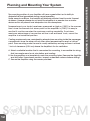
Planning and Mounting Your System
The mounting position of your Amplifier will have a great effect on its ability to
dissipate the heat generated during normal operation.
Under normal conditions, the heatsink will dissipate sufficient heat to avoid thermal
shutdown. However please do not install the amplifier in a wooden box or similar
device as this will prevent heat dissipation into the atmosphere.
Temperatures in car trunks have been measured as high as (155'F) in the summer
time. since the thermal shut-down point for the amplifier is (158'F) it is easy to
see that it must be mounted for maximum cooling capability. To achieve
maximum advantage of convection air flow in an enclosed trunk, mount the
amplifier in a horizontal position.
Cooling requirements are considerably relaxed when mounting inside the passenger
compartment since the driver will not often allow temperatures to reach a critical
point. Floor mounting under the seat is usually satisfactory as long as there is at least
1 inch of clearance (2.54 cm) above the Amplifier's fins for ventilation.
A. Select a suitable location that is convenient for mounting, is accessible for wiring.
And has ample room for air circulation and cooling.
B. Use the amplifier as a template to mark the mounting holes. Remove the Amplifier
and drill holes. Use extreme caution, inspect underneath surface before drilling!
C. Secure the Amplifier using the screws provided.
PLANNING & MOUNTING YOUR SYSTEM
12

WIRING DIAGRAM
Wiring Diagram
X3.60
X3.71
SUB WOOFER
1 OHM
13
SUB WOOFER
1 OHM

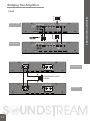
BRIDGING TWO AMPLIFIERS
X3.60
Bridging Two Ampliers
MASTERSLAVE
MASTER AMP
SLAVE AMP
MASTER AMP
SLAVE AMP
MASTERSLAVE
14
SPEAKER IMPEDANCE
2 OHMS

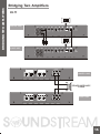
X3.71
Bridging Two Amplifiers
MASTERSLAVE
MASTER AMP
SLAVE AMP
SPEAKER IMPEDANCE
2 OHMS
MASTER AMP
SLAVE AMP
MASTERSLAVE
BRIDGING TWO AMPLIFIERS
15

Tuning on the Amplifier
Adjusting The Audio Level
The amplifier automatically turns on a few seconds after you turn your vehicle's ignition
switch to ACC or ON or turn on your auto sound system, depending on how you wired
the system. The POWER indicator on the top of the amplifier lights when the amplifier is on.
Important : Your amplifier requires 30 amps or more of power from your vehicle's
battery during operation. To protect your battery from discharging,
do not operate the amplifier unless your vehicle is running.
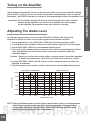
FREQUENCY (Hz)
10
-30dB
-20dB
-10dB
0dB
+10dB
+20dB
FREQUENCY RESPONSE
RESPONSE (dB)
BASS BOOST ON
45
35 80
100 500 1K 5K 20K 50K
NOTE:
Raising the Bass frequency allows higher frequencies to reach the bass speakers
while blocking lower frequencies from midrange speakers. Lowering the Bass
frequencies allows lower frequencies to reach the midrange speakers while
blocking higher frequencies from bass speakers.
For the best performance, you must set GAIN (MIN / MAX) on the side of the
amplifier to adjust the level of the audio signals that enter the amplifier.
1. Use a screwdriver to turn GAIN (MIN / MAX) fully counterclockwise to MIN.
2. Turn the auto sound system's volume control to about one-third of its full range.
3. Adjust GAIN (MIN / MAX) to a comfortable listening level.
4. Turn up the auto sound system's volume control until the sound begins to distort.
Then immediately turn the volume down to a point just before where the
distortion began.
Caution : Never turn up the auto sound system's volume control more than needed
to adjust the audio level, more than two thirds of its maximum volume.
5. Adjust GAIN (MIN / MAX) until the sound is at the maximum level you want the
amplifier to produce.
6. Adjust the auto sound system's volume control to a comfortable listening level.
ADJUSTING & TUNING
16

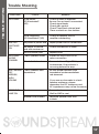
Trouble Shooting
SYMPTOMS
NO SOUND
AMP NOT
SWITCHING
ON
NO SOUND
IN ONE
CHANNEL
AMP TURNING
OFF
MEDIUM /
HIGH
VOLUME
PROTECTION
LAMP ON
Is the power
Is the Diagnostic
LED illuminated? (YES)
No power to power wire Repair power wire or connections.
No power to remote
wire with receiver on
Check connections to radio.
Burnt or broken fuse
Check Speaker Leads Inspect for short circuit or an
open connection.
Reverse Left and Right RCA inputs
to determine if the problem is
occurring before the amp.
Be sure proper speaker load
impedance recommendations
are observed.
(If you use an ohmmeter to check
speaker resistance, please
remember that DC resistance and
AC impedance may not be the same.)
Check Audio Leads
Check Speaker load
impedance
Shut down Turn radio down
Wait for AMP to cool
Speaker wires shorted Separate speaker wires and
insulate
Check for speaker short or
amplifier overheating.
Check all fuses to amplifier.
Be sure Turn-on lead is connected
Check signal leads.
Check gain control.
Check Tuner/Deck volume level.
Clean contacts on fuse holders.
LED illuminated?
(NO)
CHECK
REMEDY
Replace fuse
TROUBLE SHOOTING
17

Page is loading ...
Page is loading ...
Page is loading ...
-
 1
1
-
 2
2
-
 3
3
-
 4
4
-
 5
5
-
 6
6
-
 7
7
-
 8
8
-
 9
9
-
 10
10
-
 11
11
-
 12
12
-
 13
13
-
 14
14
-
 15
15
-
 16
16
-
 17
17
-
 18
18
-
 19
19
-
 20
20
-
 21
21
-
 22
22
-
 23
23


Soundstream X3.60 User manual
- Category
- Car audio amplifiers
- Type
- User manual
- This manual is also suitable for
Ask a question and I''ll find the answer in the document
Finding information in a document is now easier with AI
Related papers
-
Soundstream XXX-6500 Owner's manual
-
-
Soundstream Technologies LW1.1100D User manual
-
Soundstream Edge Series EGA1400D User manual
-
-
 Soundstream Technologies SMA2.480 User manual
-
-
-

Other documents
-
Cadence MONO CLASS D Owner's manual
-
AudioBahn A4KDN Operating Instructions Manual
-
Power Acoustik OV1-3000D User manual
-
Lanzar Vibe 1000.1D Owner's manual
-
-
Lanzar Car Audio HTG 2600D User manual
-
Rockville Phenom RXA-T1 Owner's manual
-
-
-
 Boss Audio Systems PH3000D User manual
