Soundstream Edge Series EGA1400D User manual

Category
Car audio amplifiers
Type
User manual
EDGE DIGITAL AMPLIFIER OWNER MANUAL
TROUBLE SHOOTING
13
ADJUSTING & TUNING
12
PLANNING & MOUNTING YOUR SYSTEM
10
WIRING DIAGRAMS
11
CONTROLS & FUNCTIONS
EGA900D / 1400D / 1700D
FEATURES & SPECIFICATIONS
TABLE OF CONTENTS
TABLE OF CONTENTS
INTRODUCTION
2
3
4~10
4
INTRODUCTION
INTRODUCTION
2
Amplifier's provide high-performance sound reinforcement for you mobile audio
equipment. The Multi-Mode bridging capabilities allow flexibility in hosting several
different speaker configurations.
To achieve optimum performance, it is highly recommended that you read this Owners
Manual before beginning installation.
FEATURES
FEATURES & SPECIFICATIONS
3
TST ( Twin Stack Technology) 2 amplifier's to drive one voice coil
effectively doubling the power.
Class D circuitry
High quality FR-4 circuit board
Continuously variable low-pass filter (50Hz to 150Hz)
Continuously variable subsonic filter (15Hz to 40Hz)
Subwoofer equalizer control switch
Phase inversion switch (0 -180 )
Platinum RCA input and output
OEM floating ground input
Platinum 4-gauge power connectors
1-ohm stable
>80dB S/N ratio
0.30% THD
Includes EGA-RM remote bass control
Specifications
MODEL
CHANNEL
RMS @ 4 OHM
@ 2 OHM @ 1 OHM
FUSES
DIMENSIONS
EGA900D
EGA1400D
EGA1700D
1
1
1
225 x 1
350 x 1
425 x 1
450 x 1
700 x 1
850 x 1
900 x 1
1400 x 1
1700 x 1
30A x 3
30A x 4
30A x 5
11" x 2.4" x 14.6"
11" x 2.4 x 16.9"
11" x 2.4 x 20"
Controls & Functions
CONTROLS & FUNCTIONS
4
EGA900D / 1400D / 1700D
1 2
3
4
5 12
1013978
1
978
GND REM+12V
6
11
14
SPEAKER
LINE OUT
L-CH L-CH R-CHR-CH
INPUTS
PROTECT
MAX
OFF
EGA900D
GND
POWER
REM+12V
FUSES
MIN
ON
CONNECTION
BRIDGED
REMOTE
POWER
BASS
BOOST
50 150
LOW
PASS
0 180
PHASE
SHIFT
15 40
SUB
SONIC
MASTER SLAVE
LEVEL
MIN MAX
LEVEL
EGA900D / EGA1400D / EGA1700D
1.Speaker terminals
2. Input Sensitivity Adjustment
Controls & Functions
3. Low Level Input RCA jacks
SPEAKER
TOP
FRONT
LINE OUT
L-CH L-CH R-CHR-CH
INPUTS
EGA900D / EGA1400D / EGA1700D
CONTROLS & FUNCTIONS
5
This control adjusts the amplifier's input sensitivity. Input sensitivity is variable from 200 Millivolts to
8 volts. Clockwise increases sensitivity. Counterclockwise decreases sensitivity. The amplifier can
be driven to full power with a wide range of signal levels. A lower signal level will require
increased sensitivity for full power. A higher signal level will require decreased sensitivity.
Avoid setting sensitivity lower than necessary as this would introduce unwanted distortion.
These inputs are for signal cables from the source. Always use high quality shielded RCA cables.
CONTROLS & FUNCTIONS
6
5. Bass Boost Switch
6. BRIDGED
4. Low Level OUT RCA jacks
LINE OUT
L-CH L-CH R-CHR-CH
INPUTS
EGA900D / EGA1400D / EGA1700D
OFF ON
BASS
BOOST
EGA900D / EGA1400D / EGA1700D
CONNECTION
BRIDGED
MASTER SLAVE
EGA900D / EGA1400D / EGA1700D
The LINE OUT allows you to build multiple amplifier systems without having to use splitter cords
to distribute the signal. Now it is simply a matter of bringing one set of RCAS into the first amplifier,
then using the line out RCA jacks as the feed to the next amplifier.
By using the bass boost function, bass notes at 35Hz - 80Hz are emphasized as much as 10dB.
Controls & Functions
GND
POWER
REM+12V
GND
POWER
REM+12V
GND
POWER
REM+12V
7. B-Terminal (Chassis ground)
8. B+ Terminal (Battery positive)
9. Remote Power On
Controls & Functions
GND REM+12V
TOP FRONT
FRONT
GND REM+12V
TOP
FRONT
GND REM+12V
TOP
EGA900D / EGA1400D / EGA1700D
CONTROLS & FUNCTIONS
7
To avoid unwanted ignition noise caused by ground loops, it is essential that the Amplifier be
grounded to a clean, bare, metal surface of the vehicles chassis.
Note : GROUND WIRE SHOULD NOT BE EXTENDED MORE THAN 3 FT (1 METER).
Due to the power requirements of the Amplifier, this connection should be made directly to the
positive(+) terminal of battery. For safety measure, install an in-line fuse Holder (not included)
as close to the battery positive(+) terminal as possible with an ampere rating not to exceed
total value of fuses in Amp.
CONTROLS & FUNCTIONS
10. Low Pass Filter Control
50 150
LOW
PASS
EGA900D / EGA1400D / EGA1700D
15 40
SUB
SONIC
EGA900D / EGA1400D / EGA1700D
11. Subsonic Filter Control
Variable Subsonic Filter (15Hz - 40Hz) :
The Subsonic filter will roll off all of the unwanted frequencies below 15Hz - 40Hz.
This will allow the amplifier to use that wasted power on the audible bandwidth.
12. Phase Shift Switch
0 180
PHASE
SHIFT
EGA900D / EGA1400D / EGA1700D
CONTROLS & FUNCTIONS
8
To remote wire car stereo.
This amplifier is turned "ON" remotely when vehicle's stereo is turned "ON"
Note : IF YOUR RADIO DOES NOT HAVE +12 VOLT OUTPUT LEAD WHEN TURNED ON, THE "REMOTE"
TERMINAL ON THE AMPLIFIER CAN BE CONNECTED TO VEHICLES ACCESSORY CIRCUIT WHICH
PROVIDES +12V WHEN THE CAR IS ON.
Variable Low Pass Filter (50Hz - 150Hz) :
For use as a dedicated subwoofer channel, set filter switch to "LPF". Adjust variable crossover
frequency with control as desired. The amplifier input circuit filters out everything above 50Hz ...
...150Hz (dependent on the adjustment of the frequency control), so only the deepest bass
notes are amplified.
PHASE SHIFT SWITCH (0 TO 180 DEGREES) :
Allows you to change the phase of your subwoofer from 0 to 180 degrees to help compen-
sate for timing differences between drivers.
Controls & Functions
REMOTE
13. Remote Control Input - Fig 1.
EGA900D / EGA1400D / EGA1700D
PROTECT
POWER
14. LED indicator
Controls & Functions
CONTROLS & FUNCTIONS
9
EGA900D / EGA1400D / EGA1700D
POWER : This GREEN LED will illuminate when the amplifier is turned "ON". If it fails to
illuminate, check the power connections to the Amplifier and fuses.
PROTECT: The amplifier protection circuitry will disable the amplifier if input overload, shor t circuit
or extremely high temperature conditions are detected. When the protection mode is in operation,
the LED indicator on the side panel will be illuminated, indicating the amplifier has gone into a self-
preservation mode.
If you observe that the Protection LED is lit, please check the system carefully to determine what
has caused the protection circuit to engage. The amplifier can be reset by turning the remote power
off and then on again. If the amplifier shut down due to a thermal overload condition, please allow
it to cool down before restarting. If the amplifier shut down because of an input overload or short
circuit, be sure to repair these conditions before attempting to power up the amplifier again.
Remote Boost Control : EGA-RM
Planning and Mounting Your System
PLANNING & MOUNTING YOUR SYSTEM
10
The mounting position of your Amplifier will have a great effect on its ability to dissipate the heat
generated during normal operation.
Under normal conditions, the heatsink will dissipate sufficient heat to avoid thermal shutdown.
However please do not install the amplifier in a wooden box or similar device as this will
prevent heat dissipation into the atmosphere.
Temperatures in car trunks have been measured as high as (155'F) in the summer time.
since the thermal shut-down point for the amplifier is (158'F) it is easy to see that it must be
mounted for maximum cooling capability. To achieve maximum advantage of convection air
flow in an enclosed trunk, mount the amplifier in a horizontal position.
Cooling requirements are considerably relaxed when mounting inside the passenger compart-
ment since the driver will not often allow temperatures to reach a critical point.
Floor mounting under the seat is usually satisfactory as long as there is at least 1 inch of clearan-
ce (2.54 cm) above the Amplifier's fins for ventilation.
A. Select a suitable location that is convenient for mounting, is accessible for wiring.
And has ample room for air circulation and cooling.
B. Use the amplifier as a template to mark the mounting holes. Remove the Amplifier and drill
holes. Use extreme caution, inspect underneath surface before drilling!
C. Secure the Amplifier using the screws provided.
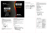
Remote Bass Boost Control : This control adjusts the Bass Boost gain for the amplifier's speaker
output (0 - +12dB)
Fig 1.
LEVEL
EGA-RM
MAXMIN
Remote Bass Boost Control : EGA-RM
MAX
O
F
F
M
IN
O
N
B
AS
S
B
O
OS
T
5
0
15
0
L
O
W
P
A
S
S
15
4
0
SUB
SON
IC
L
E
V
E
L
EGA900D / 1400D / 1700D
Bridging Two Amplifier's
WIRING DIAGRAMS
11
SUB WOOFER
1 OHM
SPEAKER
SPEAKER
LINE OUT
L-CH L-CH R-CHR-CH
INPUTS
PROTECT
MAX
OFF
EGA900D
GND
POWER
REM+12V
FUSES
MIN
ON
CONNECTION
BRIDGED
BRIDGED
BRIDGED
REMOTE
POWER
BASS
BOOST
50 150
LOW
PASS
0 180
PHASE
SHIFT
15 40
SUBSONIC
MASTER
MASTER
MASTER
SLAVE
SLAVE
SLAVE
LEVEL
SPEAKER
LINE OUT
L-CH L-CH R-CHR-CH
INPUTS
PROTECT
MAX
OFF
EGA900D
GND
POWER
REM+12V
FUSES
MIN
ON
CONNECTION
BRIDGED
REMOTE
POWER
BASS
BOOST
50 150
LOW
PASS
0 180
PHASE
SHIFT
15 40
SUBSONIC
MASTER SLAVE
LEVEL
SPEAKER IMPEDANCE
2 OHMS
MASTER AMP
SLAVE AMP
BRIDGED SWITCH : MASTER POSITION
BRIDGED MODE
BRIDGED SWITCH : SLAVE POSITION
Tuning on the Amplifier
Adjusting The Audio Level
ADJUSTING & TUNING
12
The amplifier automatically turns on a few seconds after you turn your vehicle's ignition switch to
ACC or ON or turn on your auto sound system, depending on how you wired the system. The
POWER indicator on the top of the amplifier lights when the amplifier is on.
Important : Your amplifier requires 30 amps or more of power from your vehicle's battery during
operation. To protect your battery from discharging, do not operate the amplifier
unless your vehicle is running.
NOTE:
Raising the Bass frequency allows higher frequencies to reach the bass speakers while
blocking lower frequencies from midrange speakers. Lowering the Bass frequencies
allows lower frequencies to reach the midrange speakers while blocking higher frequencies
from bass speakers.
For the best performance, you must set GAIN (MIN / MAX) on the side of the amplifier to adjust
the level of the audio signals that enter the amplifier.
1. Use a screwdriver to turn GAIN (MIN / MAX) fully counterclockwise to MIN.
2. Turn the auto sound system's volume control to about one-third of its full range.
3. Adjust GAIN (MIN / MAX) to a comfortable listening level.
4. Turn up the auto sound system's volume control until the sound begins to distort. Then
immediately turn the volume down to a point just before where the distortion began.
Caution : Never turn up the auto sound system's volume control more than needed to adjust
the audio level, more than two thirds of its maximum volume.
5. Adjust GAIN (MIN / MAX) until the sound is at the maximum level you want the amplifier to
produce.
6. Adjust the auto sound system's volume control to a comfortable listening level.
FREQUENCY (Hz)
10
-30dB
-20dB
-10dB
0dB
+10dB
+20dB
FREQUENCY RESPONSE
RESPONSE (dB)
BASS BOOST ON
45
35 80
100 500 1K 5K 20K 50K
Trouble Shooting
TROUBLE SHOOTING
13
SYMPTOMS
NO SOUND
AMP NOT
SWITCHING ON
NO SOUND
IN ONE CHANNEL
AMP TURNING
OFF
MEDIUM / HIGH
VOLUME
PROTECTION
LAMP ON
Is the power
Is the Diagnostic
LED illuminated? (YES)
No power to power wire Repair power wire or connections.
No power to remote
wire with receiver on
Check connections to radio.
Burnt or broken fuse
Check Speaker Leads Inspect for short circuit or an
open connection.
Reverse Left and Right RCA inputs
to determine if the problem is
occurring before the amp.
Be sure proper speaker load
impedance recommendations
are observed.
(If you use an ohmmeter to check
speaker resistance, please
remember that DC resistance and
AC impedance may not be the same.)
Check Audio Leads
Check Speaker load
impedance
Shut down Turn radio down
Wait for AMP to cool
Speaker wires shorted Separate speaker wires and
insulate
Check for speaker short or
amplifier overheating.
Check all fuses to amplifier.
Be sure Turn-on lead is connected
check signal leads.
Check gain control.
Check Tuner/Deck volume level.
Clean contacts on fuse holders.
LED illuminated?
(NO)
CHECK
REMEDY
Replace fuse
END
  • Page 1 1
  • Page 2 2
  • Page 3 3
  • Page 4 4
  • Page 5 5
  • Page 6 6
  • Page 7 7
  • Page 8 8
  • Page 9 9
  • Page 10 10
  • Page 11 11
  • Page 12 12
  • Page 13 13
  • Page 14 14
  • Page 15 15

Soundstream Edge Series EGA1400D User manual

Category
Car audio amplifiers
Type
User manual

Ask a question and I''ll find the answer in the document

Finding information in a document is now easier with AI