Page is loading ...

P
C
X
-
V
1
2
P
C
X
-
V
1
2
True
diversity
VHF
wireless
receiver
True
diversity
VHF
wireless
receiver
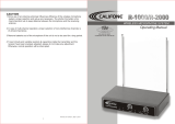
OPERATING GUIDE

INTRODUCTION
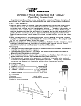
Thank you for selecting a Peavey Pro Comm PCX-
V12 quartz controlled single channel true diversity wireless
microphone system. Before operating and installing this
system please read this instruction manual carefully and
thoroughly in order to attain the correct operating
procedures and to achieve the best results.
True Diversity Receiver
The Peavey Pro Comm PCX-V12 quartz controlled
receiver is a true diversity wireless system. This system is
also equipped with “Superior frequency tracking and muting
techniques” that is effective in eliminating the random noise
interference when the receiver is in standby state. The
Peavey Pro Comm PCX-V12 receiver is equipped with both
balanced and unbalanced outputs.
This system includes the following accessories:
• AC/DC Adapter
• Mic Clip
• Antenna (2)
• Instruction Manual
1. UNIT FEATURES AND FUNCTIONS
A. Front Panel
Figure 1
1
2
3 4 65
3

1. Antenna Input Connector A
2. Power Switch and Indicator:
When the switch is turned on the red indicator
illuminates to denote normal power status.
3. RF Signal Level Indicator:
Indicates the RF signal strength received from the
microphone. As soon as the signal is emitted from
the microphone the LED indicator illuminates.
4. Audio Signal Level Indicator:
Indicates the audio signal level. As soon as the
microphone signal is modulated, the LED indicator
illuminates.
5. Volume Control:
Adjusts the AF output level of the receiver.
6. Antenna Input Connector B
B. Rear Panel
7
8 9 10 11
Figure 2
4

7. DC 12V Input Jack:
Connect the 12V DC plug from the AC/DC adapter.
8. Balanced Audio Output Jack:
XLR type connector
9. Unbalanced Audio Output Jack:
1/4" Phone Jack
10. Unbalanced Level Switch:
“LOW selection is for “Microphone-Level” output.
“HIGH” selection is for “Line-Out” level output.
11. Squelch Adjustment:
Adjust the squelch level to eliminate the RF noise
interference at the receiver.
2. INSTALLATION OF THE RECEIVER
1. Install one of the antennas at the antenna input
connector A. Then install the other antenna at
the antenna input connector B.
2. AC/DC Power Connection:
Figure 3
Connect the AC/DC adapter cable to the DC 12V
input jack. Then plug the adapter unit into an
appropriate AC outlet as shown in Figure 3. Caution:
Make sure the correct voltage is present at the AC
outlet as indicated on the AC/DC adapter.
5

3. Audio Output Connection:
a. Unbalanced Level Switch Setting Position:
Make sure to match the unbalanced output
setting to the device input setting. The
incorrect setting could result in low sensitivity
level or over load distortion. Ex. (If you are
going into the “Line” input on a mixer or
amplifier then the switch should be set to the
high position. If you are going into the “Mic”
input of an amplifier or mixer then the switch
should be set to the low position.)
b. Unbalanced Output:
Connect the 1/4" phone plug of the audio cable
into the unbalanced output connector on the
back of the receiver. Connect the other end of
the cable to the proper input of the desired
device. Make sure the unbalanced level switch
is in the proper position before applying power.
c. Balanced Output:
Connect the male XLR connector into the
balanced output connector on the back of the
receiver. Connect the other end of the cable
into the “Mic/Balanced” input of the desired
device. The characteristics of the 3-pin XLR
connector are shown below in Figure 4.
Figure 4
GND PIN 1
PIN 3
PIN 2
6

3. TWO 19/2-INCH UNITS RECEIVER INSTALLATION
A. Setup for single half-rack receiver
1. Push the rack mount brackets (RM-11)
upwards until it is firmly attached to the
receiver. (Figure 5)
Figure 5
B. Setup for dual half-rack receivers
1. Remove the screws at the top and
bottom of the receiver where they will
be joined together. Remove one steel
plate from each receiver. Push the
receivers next to each other. Refer to
Figure 6.
2. Insert the steel plate in between the two
receivers (top and bottom). Align and
fasten the screws tightly as shown in
Figure 6.
3. Align and fasten the rack mount
7

brackets (RM-12) on the outer sides of
both receivers as shown in Figure 6.
Figure 6
4. After completion, it can be rackmounted
into an EIA standard rack case. Shown
in Figure 7.
5. Make sure that the system performs
correctly by placing the system away
from noise sources. Place the receiver
at least one meter above the ground
and one meter away from noise
sources. Place the microphone at least
one meter away from the receiving
antenna, as shown in Figure 8.
Figure 7 Figure 8
8

4. OPERATION INSTRUCTIONS
1. Turn the volume controls of the receiver and
device in use to a minimum setting before
turning on the microphone transmitter. After
the receivers power switch is set to the on
position, the power switch’s red indicator
illuminates to denote normal power status.
2. If the SIGNAL LED indicators of the receiver
are illuminated before switching on the
microphone or transmitter, it indicates the
receiver is receiving interference signals. The
more LEDs that illuminate the more severity of
interference. This system has “Pilotone” and
“NoiseLock” dual-squelch features so noise
output will not occur. If multiple channels are
used and both SIGNAL and AUDIO LEDs
illuminate before the transmitter is turned on,
simply adjust the Squelch controls clockwise
until the AUDIO signal indicators extinguish.
(Figure 9). However, by adjusting the
squelch controls it affects the sensitivity level
of the receiver, therefore, shortening the
operating distance and decreasing the
stability.
Figure 9
3. Under normal circumstances, the SIGNAL
indicator lights up when a microphone or
transmitter is turned on near the receiver to
indicate the receiver is ready for normal
operation. Once sounds enter into the
9

microphone the AUDIO LED indicators will
illuminate according to the strength of sound
level. If the LEDs do not illuminate or sound is
not present at the output, the system is not
functioning properly and must be checked.
4. Receiver and Amplifier Volume Adjustment:
a. Single-channel Unbalanced Audio
Output: Switch the level switch on the
rear panel of the receiver to the left
“LOW” Position, then adjust the volume
control to twelve o’clock position.
Adjust the volume control of the
amplifier or mixer to an appropriate
sound level. The volume control is used
for fine adjustment of the microphone
sensitivity. When the knob is turned to
the twelve o’clock position the output
sensitivity level of the wireless
microphone is the same as a normal
dynamic microphone. Once the receiver
output level is appropriately adjusted,
do not adjust the volume control again.
Adjust the mixer or amplifier volume
control if the sound level needs to
increase or decrease.
b. Balanced Output: Adjust according to
the unbalanced audio output method in
the previous step. (Note: The level
switch does not effect the balanced
output.)
c. To obtain the same sensitivity level
when using a wireless microphone and
a wired microphone with one amplifier
or mixer connect both the receiver
output and the wired output to a “MIC-
10

IN” input jack of the amplifier or mixer.
Adjust the volume controls of the
amplifier or mixer to the same desired
level, then properly fine adjust the
receiver volume control to match the
same sensitivity as the wired
microphone.
d. If the receiver output level is adjusted to
a level that is near the maximum input
level of the desired device, it will cause
saturation distortion of the device when
the receiver output level is increased
due to a increase in level by the sound
source. Conversely, S/N ratio will
decrease if the receiver volume control
is adjusted too low.
5. Plug the cable of the mains unit into DC
socket on the receiver’s back panel. Thread
the cable through the cable grip as shown in
the figure below (Figure 10). The cable
grip prevents the connector from being pulled
off by accident.
Figure 10
11

5. Caution
1. Since the installation of the antenna
influences the operating efficiency of
the receiver, the most important rule is
to minimize the distance as much as
possible between the receiving antenna
and the microphone for the best
reception and performance.
2. The output voltage of the external DC
power supply should not be below 12V,
otherwise it will not work properly. If the
voltage is over 15V some components
of the receiver will be damaged due to
excessive current draw. Use a power
supply with a 1A minimum rating.
12

HANDHELD WIRELESS MICROPHONE
The Peavey Pro Comm PCX-V12 handheld wireless
microphone is a modular design. It also incorporates
“Superior frequency tracking and muting techniques” dual-
squelch to eliminate noise interference.
1. Unit Features and Functions
1. Grille: Protects cartridge and
prevents breathing and wind
POP noises.
2. Housing: Upper portion that is
connected to the capsule
module. Internally it holds the
transmitter PCB and battery
compartment.
3. Battery Status Indicator:
Indicates the power on/off and
battery status. When the
power switch is turned ON,
the red LED indicator flashes
briefly and then go out,
indicating normal battery
status. If no flash occurs, it has
either no battery or the battery
is drained or installed
incorrectly. The power led will
also warn when the battery is
weak by remaining on after
power up. A battery
replacement is then necessary.
4. Power On-off Switch:
Slide the power switch to the “ON” position for
use or to the “OFF” position when not in use.
5. Battery Compartment:
Designed to accommodate one 9V battery.
6. Battery Cap: Covers battery in the battery
compartment.
Figure 11
13
1
2
3
456

2. BATTERY INSERTION
1. Unscrew the battery cap in a counter-
clockwise direction.
2. Insert a 9V battery into the battery
compartment according to the correct polarity
as shown in Figure12. The moment the
battery touches the terminals of the
compartment, the indicator will flash briefly.
This means the polarity is correct. However, if
no flash occurs, this indicates wrong insertion
or battery is dead. Please re-insert the battery
according to its correct polarity or exchange it
for a fresh battery.
3. OPERATING INSTRUCTIONS
1. When the microphone is switched on the
indicator will flash briefly indicating normal
operation.
2. After the microphone is switched on the RF
SIGNAL LED indicator of the receiver
illuminates. As the signal strength increases
the number of illuminated LEDs will increase.
If only the red LED illuminates this indicates
abnormal receiving status.
3. During usage the AUDIO LED indicator of the
receiver will illuminate according to the sound
strength input to the microphone. When the
red LED is illuminated, it denotes the
maximum sound pressure level is being
reached but does not represent distortion.
14
Figure 12

4. When the microphone is not in use make sure
to turn it off to extend the battery life. Remove
the battery from the battery compartment if the
microphone will not be in use for a long period
of time. If a rechargeable battery is used take
it out for a recharge as necessary.
BELT PACK TRANSMITTER
1. Unit Features and Functions
1. 4-pin Jack Input Connector: Connects to the
Peavey Pro Comm 4-pin connector. Allow 5
different input configurations (See the five
ways of connection on an AF input connection,
page 19.)
2. Transmitting Antenna: 1/4 wavelength
transmitting antenna
3. GT/MT
Switch: Switch
to the GT
position for
electric guitar
use ONLY. Gain
Control is
irrelevant for
“GT” mode.
Switch to the
“MT” position
for condenser
microphone,
wired micro-
phone or
Line-in use.
Gain Control
works in the “MT” mode for input sensitivity
adjustments.
15
1
7
2
3
4
5
6
Figure 11

4. Gain Control: Adjusts the input gain to an
appropriate level.
5. Transmitter Housing: Contains the PCB and
battery.
6. Battery Status Indicator: Indicates the power
on/off and battery status.
a. When the power switch is turned on the
LED indicator flashes briefly, indicating
normal battery status.
b. If the LED illumination is sustained at
either power on or during usage the
battery level is low. The old battery should
be replaced with a new one.
7. Power Switch: Switch to ON position for
operation. Switch to OFF position when not in
use.
8. Battery Compartment and Cover:
Accommodates one 9V battery. (Figure 14)
2. OPERATING INSTRUCTIONS
Figure 14
16
8

1. Push down on the battery cover to open the
battery compartment.
2. Insert a 9V battery into the battery compartment
according to the correct polarity as shown in
Figure 14. Then push up on the battery cover to close
the battery compartment.
3. The LED indicator will flash briefly when
power is turned on to indicate normal battery
status. If no flash occurs it has either no
battery, the battery is drained or installed
incorrectly. Change accordingly.
4. 4-Pin Jack: Volume can be adjusted by the
gain control. Gain control has no effect when
the switch is in the “GT” position (Guitar).
5. 4-Pin Jack: Align and insert the 4-pin plug into
the jack accordingly and tighten it in the
clockwise direction as shown in Figure 15.
Figure15
17

3. AF 4-PIN INPUT CONNECTION METHODS
1. 2-Wire Electret condenser microphone Capsule
2. 3-Wire Electret condenser microphone Capsule
3. Dynamic Microphone
4. Electric Guitar
5. Line-in (Impedance 8 KΩAttenuated 10 dB)
18

SPECIFICATIONS
1. Overall: VHF PCX-V12
1. Carrier Frequency Range: VHF Band 160~250 MHz
2. Oscillation Mode: Quartz-controlled
3. Channel: 1-channel fixed
4. Stability: + 0.005 % with temperature compensation
5. Max. Deviation: + 15 KHz with level limiting
6. Dynamic Range: > 110 dB
7. S/N Ratio: > 102 dB
8. T.H.D.: < 0.5 %
9. Squelch: “Superior frequency tracking and muting
techniques” dual-squelch
10. Frequency Response: 60 Hz~18 KHz + 3 dB
2. Receiver: VHF PCX-V12
1. Receiving Method: True Diversity Single Channel
2. Sensitivity: 15 dBuV at S/N > 80 dB
3. Image Rejection: > 60 dB
4. Spurious Rejection: > 75 dB
5. Audio Output: can switch between –2 dB/5 K Ω and
-12 dB/600 Ω unbalanced and balanced
6. Power Supply: 12~15 VDC/0.5 A
7. Panel: 19/2-inch, half-rack size
8. Dimensions (m/m): 210(L) x 175(W) x 44(H)
9. Weight: Approx. 0.6 Kgs
3. Transmitter: VHF PCX-V12
1. Mic Element: Condenser Microphone Capsule
2. Antenna: Built-in
3. RF Output: 10~50 mW (according to regulation)
4. Spurious: < -45 dBc
5. Battery: One 9-Volt Battery
6. Dimensions (m/m): 49 x 234(L)
7. Weight: 250 grams (without battery)
8. 30-hour battery life per single alkaline
19

20
TROUBLESHOOTING GUIDE
Symptom Distance Possible Possible
Cause Solution
No AF signal Any low transmitter replace battery
and no RF signal battery voltage
No AF signal long out of range move transmitter
and no RF signal closer to receiver or
obstecles
No AF signal any microphone or check input source
but normal RF signal other input source
Distortion with no any low transmitter replace battery
AF peak indication battery voltage
Noise with low AF any strong RFI identify source and
signal and normal eliminate, or change
RF signal frequency of wireless
microphone system
Intermittent AF signal long out of range move transmitter and
low RF signal closer to RCV
Intermittent AF and average obstructions remove obstructions
RF signals in signal path or reposition transmitter
and/or RCV
MULITPLE SYSTEM
Symptom Distance Possible Action
Cause
Distortion on two any units on same change frequencies
or more systems without frequency
Distortion on one transmitter- transmitter + transmitter change frequencies
or more systems without transmitter short intermod
Distortion on one transmitter- transmitter + transmitter increase transmitter
or more systems without transmitter short intermod to transmitter distance
transmitter-receiver transmitter +transmitter change frequencies
short receiver intermod
Distortion on one or more transmitter-receiver transmitter +transmitter increase transmitter
systems without short receiver intermod to receive distance
AF peak indication

PEAVEY ELECTRONICS CORPORATION LIMITED WARRANTY
Effective Date: July 1, 1998
What This Warranty Covers
Your Peavey Warranty covers defects in material and workmanship in Peavey products purchased and serviced in the
U.S.A. and Canada.
What This Warranty Does Not Cover
The Warranty does not cover: (1) damage caused by accident, misuse, abuse, improper installation or operation, rental,
product modification or neglect; (2) damage occurring during shipment; (3) damage caused by repair or service per-
formed by persons not authorized by Peavey; (4) products on which the serial number has been altered, defaced or
removed; (5) products not purchased from an Authorized Peavey Dealer.
Who This Warranty Protects
This Warranty protects only the original retail purchaser of the product.
How Long This Warranty Lasts
The Warranty begins on the date of purchase by the original retail purchaser. The duration of the Warranty is as fol-
lows:
Product Category Duration
Guitars/Basses, Amplifiers, Pre-Amplifiers, Mixers, Electronic
Crossovers and Equalizers 2 years *(+ 3 years)
Drums 2 years *(+ 1 year)
Enclosures 3 years *(+ 2 years)
Digital Effect Devices and Keyboard and MIDI Controllers 1 year *(+ 1 year)
Microphones 2 years
Speaker Components (incl. speakers, baskets, drivers,
diaphragm replacement kits and passive crossovers)
and all Accessories 1 year
Tubes and Meters 90 days
[*denotes additional warranty period applicable if optional Warranty Registration Card is completed and
returned to Peavey by original retail purchaser within 90 days of purchase.]
What Peavey Will Do
We will repair or replace (at Peavey's discretion) products covered by warranty at no charge for labor or materials. If
the product or component must be shipped to Peavey for warranty service, the consumer must pay initial shipping
charges. If the repairs are covered by warranty, Peavey will pay the return shipping charges.
How To Get Warranty Service
(1) Take the defective item and your sales receipt or other proof of date of purchase to your Authorized Peavey
Dealer or Authorized Peavey Service Center.
OR
(2) Ship the defective item, prepaid, to Peavey Electronics Corporation, International Service Center, 412 Highway 11 &
80 East, Meridian, MS 39301 or Peavey Canada Ltd., 95 Shields Court, Markham, Ontario, Canada L3R 9T5. Include a
detailed description of the problem, together with a copy of your sales receipt or other proof of date of purchase as evi-
dence of warranty coverage. Also provide a complete return address.
Limitation of Implied Warranties
ANY IMPLIED WARRANTIES, INCLUDING WARRANTIES OF MERCHANTABILITY AND FITNESS FOR A PARTICU-
LAR PURPOSE, ARE LIMITED IN DURATION TO THE LENGTH OF THIS WARRANTY.
Some states do not allow limitations on how long an implied warranty lasts, so the above limitation may not
apply to you.
Exclusions of Damages
PEAVEY'S LIABILITY FOR ANY DEFECTIVE PRODUCT IS LIMITED TO THE REPAIR OR REPLACEMENT OF THE
PRODUCT, AT PEAVEY'S OPTION. IF WE ELECT TO REPLACE THE PRODUCT, THE REPLACEMENT MAY BE A
RECONDITIONED UNIT. PEAVEY SHALL NOT BE LIABLE FOR DAMAGES BASED ON INCONVENIENCE, LOSS
OF USE, LOST PROFITS, LOST SAVINGS, DAMAGE TO ANY OTHER EQUIPMENT OR OTHER ITEMS AT THE SITE
OF USE, OR ANY OTHER DAMAGES WHETHER INCIDENTAL, CONSEQUENTIAL OR OTHERWISE, EVEN IF
PEAVEY HAS BEEN ADVISED OF THE POSSIBILITY OF SUCH DAMAGES.
Some states do not allow the exclusion or limitation of incidental or consequential damages, so the above limi-
tation or exclusion may not apply to you.
This Warranty gives you specific legal rights, and you may also have other rights which vary from state to
state.
If you have any questions about this warranty or service received or if you need assistance in locating an Authorized
Service Center, please contact the Peavey International Service Center at (601) 483-5365 / Peavey Canada Ltd. at
(905) 475-2578.
Features and specifications subject to change without notice.
22
/