Biasi ActivA 25C, 30C, 35C User manual
- Category
- Water heaters & boilers
- Type
- User manual
This manual is also suitable for

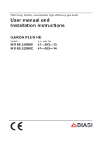
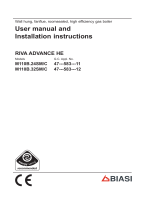
Wall hung, fanflue, roomsealed, high efficiency gas boiler
User manual and
Installation instructions
ActivA
Models G.C. Appl. No.
Activ A 25C 47-583-21
Activ A 30C 47-583-22
Activ A 35C 47-583-23

- 2 -
WARNING
Congratulations on your choice.
ActivA are condensing high effi ciency sealed chamber fan fl ue gas boilers. They are fully
electronically controlled and have electronic ignition.
The materials they are made of and the control systems they are equipped with give you
safety, a high level of comfort and energy savings to allow you to get the greatest benefi t out
of independent heating.
ActivA allow a higher effi ciency by reducing the fl ue gas temperature such that the water
vapour formed during the combustion is condensed out.
This allows a gain of useful heat that otherwise would be lost.
DANGER: The indications marked with this symbol must be observed to pre-
vent accidents of mechanical or generic origin (e.g.: injuries or bruises).
DANGER: The indications marked with this symbol must be observed to pre-
vent accidents of electric origin (electrocution).
DANGER: The indications marked with this symbol must be observed to pre-
vent the risk of fi re or explosion.
DANGER: The indications marked with this symbol must be observed to pre-
vent accidents of heat origin (burns).
ATTENTION: The indications marked with this symbol must be observed to
prevent malfunctioning and/or damage to materials of the appliance or other
objects.
ATTENTION: The indications marked with this symbol is important informa-
tion that must be carefully read.

- 3 -
WARNING
Remember that...
The manual must be read thoroughly, so that you will be able to use the boiler in a safe
and sensible way; must be carefully kept. It may be necessary for reference in the fu-
ture.
The lighting up must be carried out by competent and responsible engineer.
The manufacturer
• disclaim all liability for any translations of the present manual from which incorrect inter-
pretation may occur;
• cannot be held responsible for non-observance of instructions contained in this manual
or for the consequences of any procedure not specifi cally described.
Using the boiler...
Before lighting the boiler you are advised to have a professionally qualifi ed person
check that the installation of the gas supply
• is gas-tight;
• is of the correct gauge for the fl ow to the boiler;
• is fi tted with all the safety and control devices required by the current Regulations.
Ensure that
• check with the Installer that he has connected and terminated the pressure relief valve
in a manner which allows safe discharge. The manufacturers are not responsible for
damage caused by opening of the pressure relief valve and consequent escape of wa-
ter, if this is not connected and terminated.
• the installer has connected the condensate outlet to a suitable drain pipe.
On detecting the smell of gas:
• don’t operate any electrical switches, the telephone or any device that may produce
sparks;
• open the windows and doors at once to create a draught of air which will purge the
area;
• shut off the gas cocks;
• get the assistance of a qualifi ed person. Emergency telephone number
Tel 0800 111999.

- 4 -
WARNING
Do not touch the appliance with parts of the body that are wet or damp and/or bare
feet.
Do not block or modify the condensate outlet and pipework.
In case of structural work or maintenance near the exhaust duct and/or fume exhaust
devices or their attachments, turn off the appliance. On completion of the work, have a
professionally qualifi ed person check their effi ciency.
Repairs (under guarantee) must be carried out only by an approved engineer, using
genuine spare parts. Thus do no more than switching off the boiler yourself (see the in-
structions).
Your boiler allows heating up of water to a temperature less than boiling point;
• must be connected to a central heating system and/or a hot water supply system, com-
patible with its performance and output;
• can be used only for those purposes for which it has been specially designed;
• must not be touched by children or by those unfamiliar with its operation;
• must not be exposed to weather conditions.
During the operation it is quite normal that the boiler produces a white plume of conden-
sation vapour from the fl ue terminal. This is due to the high effi ciency of the appliance and
may be particularly evident with low outdoor temperatures.
Safe handling of substances
Biasi products are manufactured in accordance with ISO 9001 and do not, and will not,
contain any hazardous materials or substances such as asbestos, mercury or C.F.C.’s. The
appliance packaging does not contain any substances, which may be considered a hazard
to health.
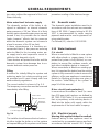
When handling or lifting always use safe techniques
keep your back straight, bend your knees, don't twist.•
move your feet, avoid bending forwards and side way sand keep the load as close to your •
body as possible.
Where possible transport the boiler using a sack truck or other suitable trolly.
Always grip the boiler fi rmly, and before lifting feel where the weight is concentrated to estab-
lish the centre of gravity, repositioning yourself as necessary.
Combustion chamber panels
Material: mineral fi bres

- 5 -
WARNING
Known hazards - Some people can suffer reddening and itching of the skin. Fibre entry into
the eye will cause foreign body irritation, which can cause severe irritation to people wearing
contact lenses. Irritation to respiratory tract.
Precautions - Dust goggles will protect eyes. People with a history of skin complaints may
be particularly susceptible to irritation. High dust levels are only likely to arise following harsh
abrasion. In general, normal handling and use will not present high risk, follow good hygiene
practices, wash hands before, touching eyes, consuming food, drinking or using the toilet.
First aid - Medical attention must be sought following eye contact or prolonged reddening of
the skin.
Thermostat / Temperature gauge
Description - Sealed phial and capillary containing liquid.
Known hazards - irritating to skin, eyes and throat. Vapour is harmful. Infl ammable -do not
extinguish with water.
Precautions - Do not incinerate. Avoid contact with broken/leaking phials. Do not purposely
puncture.
First aid - medical attention must be sought following eyes/skin contact, wash with clean
water.
Sharp Edges
Caution should be taken when handling the boiler to avoid sharp edges on the boiler.
Boiler installation and commissioning tips
The installation must be carried out by a qualifi ed person who will be responsible for
observing the current Regulations.
Installing the boiler...
Do not forget to remove the transit caps and plugs from the boiler connections these are
fi tted to every boiler.
Keep the boiler clear of dust during installation and in particular do not allow any dust or
debris to enter the top of the boiler where the fl ue connection is made. It is recommended
that you put a dust sheet over the top of the boiler until you are ready to make the fl ue
connection.

- 6 -
WARNING
Because every boiler is fi red and tested live at the factory, a small amount of water re-
mains within the boiler. It is possible for this water to initially cause the pump to seize. It is
therefore recommended that the pump rotor be manually turned to free its rotation before
turning the boiler on.
Remember to release the auto air purge before fi lling the boiler. See the instructions to
identify the location of this device.
This boiler allows to control the fl ow temperature of the central heating system at very
low levels. In case of underfl oor heating system a temperature limiting device (e.g. a
safety thermostat) is recommended to stop the boiler in case that the water temperature
exceeds the design temperature.
You are strongly advised to fl ush out the system both cold and hot in order to remove
system and installation debris.
It is also sensible to initially fi re and commission the boiler before connecting any external
controls such as a room thermostat. By this method if you have a subsequent problem
following the addition of an external control you can eliminate the boiler from your fault
analysis.
If the boiler is fi tted with a digital programmer, when setting the times for automatic opera-
tion, remember that for every “ON” time there must be an “OFF” time to follow and that
on every occasion you enter a time you must also indicate which days that you want the
boiler to follow the timed settings.
Some products incorporate an anti cycling time delay. It is normal when fi rst switching the
boiler on for the boiler to operate on heating for a few seconds then switch off. After 3 - 4
minutes has elapsed the boiler will then re ignite and operate perfectly normally. The igni-
tion delay cycle does not prevent normal operation of the boiler to provide d.h.w.
If you are in any doubts as to the installation or operation of the boiler please read the
instruction manuals thoroughly and then if necessary contact Biasi UK for advice and as-
sistance.
Please remember that if you are in any doubt about the installation of this product you can
contact our Technical Help line on tel. 0121 506 1350.

- 7 -
TABLE OF CONTENTS
1
APPLIANCE DESCRIPTION. . . . . . . . . . . . . 8
1.1 Overview. . . . . . . . . . . . . . . . . . . . . . . . . . . . . . . 8
1.2 Isolation valves. . . . . . . . . . . . . . . . . . . . . . . . . . 8
1.3 Controls panel . . . . . . . . . . . . . . . . . . . . . . . . . . 9
1.4 LCD general features . . . . . . . . . . . . . . . . . . . . 10
2 INSTRUCTIONS FOR USE . . . . . . . . . . . . 12
2.1 Warnings. . . . . . . . . . . . . . . . . . . . . . . . . . . . . . 12
2.2 Refi lling procedure . . . . . . . . . . . . . . . . . . . . . . 12
2.3 Ignition . . . . . . . . . . . . . . . . . . . . . . . . . . . . . . . 13
2.4 C.h. circuit temperature . . . . . . . . . . . . . . . . . . 14
2.5 D.h.w. temperature. . . . . . . . . . . . . . . . . . . . . . 15
2.6 Extinguishing . . . . . . . . . . . . . . . . . . . . . . . . . . 15
3 USEFUL ADVICE. . . . . . . . . . . . . . . . . . . . 17
3.1 Central Heating. . . . . . . . . . . . . . . . . . . . . . . . . 17
3.2 Frost protection. . . . . . . . . . . . . . . . . . . . . . . . . 17
3.3 Condensate drain. . . . . . . . . . . . . . . . . . . . . . . 17
3.4 Periodic maintenance. . . . . . . . . . . . . . . . . . . . 17
3.5 External cleaning . . . . . . . . . . . . . . . . . . . . . . . 18
3.6 Operational faults . . . . . . . . . . . . . . . . . . . . . . . 18
3.7 Displaying in INFO mode . . . . . . . . . . . . . . . . . 20
3.8 Remote anomaly code . . . . . . . . . . . . . . . . . . . 21
3.9 Flue probe . . . . . . . . . . . . . . . . . . . . . . . . . . . . 21
4 TECHNICAL INFORMATION. . . . . . . . . . . 22
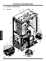
4.1 Overview. . . . . . . . . . . . . . . . . . . . . . . . . . . . . . 22
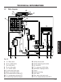
4.2 Main diagram . . . . . . . . . . . . . . . . . . . . . . . . . . 23
4.3 Hydraulic specifi cations . . . . . . . . . . . . . . . . . . 25
4.4 Expansion vessel . . . . . . . . . . . . . . . . . . . . . . . 25
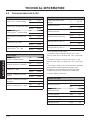
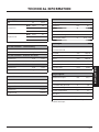
4.5 Technical data Activ A 25C . . . . . . . . . . . . . . . . 26
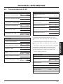
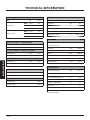
4.6 Technical data Activ A 30C . . . . . . . . . . . . . . . . 29
4.7 Technical data Activ A 35C . . . . . . . . . . . . . . . . 32
5 GENERAL REQUIREMENTS . . . . . . . . . . 35
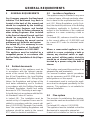
5.1 Related documents. . . . . . . . . . . . . . . . . . . . . . 35
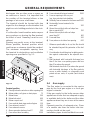
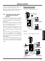
5.2 Location of appliance . . . . . . . . . . . . . . . . . . . . 35
5.3 Flue system . . . . . . . . . . . . . . . . . . . . . . . . . . . 35
5.4 Gas supply . . . . . . . . . . . . . . . . . . . . . . . . . . . . 36
5.5 Air supply . . . . . . . . . . . . . . . . . . . . . . . . . . . . . 37
5.6 Ventilation. . . . . . . . . . . . . . . . . . . . . . . . . . . . . 37
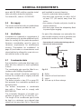
5.7 Condensate drain. . . . . . . . . . . . . . . . . . . . . . . 37
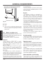
5.8 Water circulation (c.h.) . . . . . . . . . . . . . . . . . . . 38
5.9 Domestic water. . . . . . . . . . . . . . . . . . . . . . . . . 39
5.10 Water treatment . . . . . . . . . . . . . . . . . . . . . . . . 39
5.11 Electrical supply . . . . . . . . . . . . . . . . . . . . . . . . 39
6 INSTALLATION . . . . . . . . . . . . . . . . . . . . . 41
6.1 Warnings . . . . . . . . . . . . . . . . . . . . . . . . . . . . . 41
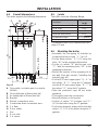
6.2 Precautions for installation . . . . . . . . . . . . . . . . 41
6.3 Installing the bracket. . . . . . . . . . . . . . . . . . . . . 42
6.4 Overall dimensions. . . . . . . . . . . . . . . . . . . . . . 43
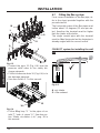
6.5 Joints . . . . . . . . . . . . . . . . . . . . . . . . . . . . . . . . 43
6.6 Mounting the boiler. . . . . . . . . . . . . . . . . . . . . . 43
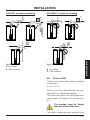
6.7 Fitting the fl ue system. . . . . . . . . . . . . . . . . . . . 44
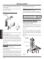
6.8 Choice of fl u . . . . . . . . . . . . . . . . . . . . . . . . . . . 45
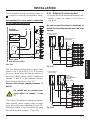
6.9 Electric connection . . . . . . . . . . . . . . . . . . . . . . 48
6.10 Connecting the room thermostat or zone
valves . . . . . . . . . . . . . . . . . . . . . . . . . . . . . . . . 50
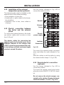
6.11 External frost protection . . . . . . . . . . . . . . . . . . 51
6.12 Installation of the external temperature probe
(optional). . . . . . . . . . . . . . . . . . . . . . . . . . . . . . 52
6.13 Electric connection between the boiler and the
external probe. . . . . . . . . . . . . . . . . . . . . . . . . . 52
6.14 Remote electric connection (optional) . . . . . . . 52
6.15 Example of hydraulic plants with hydraulic
separator . . . . . . . . . . . . . . . . . . . . . . . . . . . . . 53
7 COMMISSIONING . . . . . . . . . . . . . . . . . . . 54
7.1 Warnings. . . . . . . . . . . . . . . . . . . . . . . . . . . . . . 54
7.2 Electrical installation. . . . . . . . . . . . . . . . . . . . . 54
7.3 Gas supply installation . . . . . . . . . . . . . . . . . . . 54
7.4 Filling the d.h.w. system . . . . . . . . . . . . . . . . . . 54
7.5 Initial fi lling of the system . . . . . . . . . . . . . . . . . 54
7.6 Condensate pipe and traps . . . . . . . . . . . . . . . 55
7.7 Lighting the boiler. . . . . . . . . . . . . . . . . . . . . . . 56
7.8 Checking the gas supply pressure . . . . . . . . . . 57
7.9 Checking the inlet pressure . . . . . . . . . . . . . . . 57
7.10 Enabling functioning of the external
temperature probe by the remote control. . . . . 58
7.11 Setting the K coeffi cient of the external
temperature probe . . . . . . . . . . . . . . . . . . . . . . 59
7.12 Setting the pump post-circulation . . . . . . . . . . . 61
7.13 Selecting the reignition frequency . . . . . . . . . . 63
7.14 Checking the ignition device. . . . . . . . . . . . . . . 65
7.15 Checking the fl ue system . . . . . . . . . . . . . . . . . 65
7.16 Checking the condensate drain pipe . . . . . . . . 66
7.17 Instructing the user. . . . . . . . . . . . . . . . . . . . . . 66
7.18 Adjustment of useful c.h. output . . . . . . . . . . . . 66
7.19 Setting record . . . . . . . . . . . . . . . . . . . . . . . . . . 68
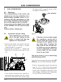
8 GAS CONVERSION . . . . . . . . . . . . . . . . . 70
8.1 Warnings. . . . . . . . . . . . . . . . . . . . . . . . . . . . . . 70
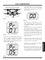
8.2 Operations and gas setting. . . . . . . . . . . . . . . . 70
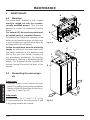
9 MAINTENANCE. . . . . . . . . . . . . . . . . . . . . 72
9.1 Warnings. . . . . . . . . . . . . . . . . . . . . . . . . . . . . . 72
9.2 Dismantling the external panels . . . . . . . . . . . . 72
9.3 Emptying the d.h.w. system . . . . . . . . . . . . . . . 73
9.4 Emptying the c.h. system . . . . . . . . . . . . . . . . . 73
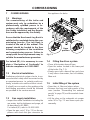
9.5 Cleaning the condensing primary exchanger
and the burner . . . . . . . . . . . . . . . . . . . . . . . . . 74
9.6 Check the pressure of the heating expansion
vessel . . . . . . . . . . . . . . . . . . . . . . . . . . . . . . . . 75
9.7 Cleaning the domestic hot water exchanger . . 75
9.8 Checking the fl ue expulsion pipe . . . . . . . . . . . 75
9.9 Combustion analysis check . . . . . . . . . . . . . . . 75
9.10 Checking the condensate drain pipe . . . . . . . . 75
9.11 Visual inspection of appliance . . . . . . . . . . . . . 76
9.12 Checking the gas supply pressure . . . . . . . . . . 76
9.13 Water inhibitor concentration . . . . . . . . . . . . . . 76
9.14 Setting the boiler chimney sweep function . . . . 76
Abbreviations used in the manual:
C.h. = Central heating
D.h.w. = Domestic hot water
D.c.w. = Domestic cold wate
Appliance category: II2H3P (gas G20 20 mbar, G31 37 mbar)
Country of destination: United Kingdom (GB) Ireland (IE)
This appliance conforms with the following EEC directive:
Gas Directive 90/396/CEE
Boiler Effi ciency Directive 92/42/CEE
Electromagnetic Compatibility Directive 89/336/CEE
Low Voltage Directive 73/23/CEE
The manufacturer, in the continuous process to improve his products, reserves the right to modify the data expressed
in the present documentation at any time and without prior notice.
The present documentation is an informative support and it can not be considered as a contract to-wards third par-
ties.

- 8 -
USE
APPLIANCE DESCRIPTION
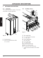
APPLIANCE DESCRIPTION1
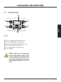
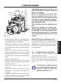
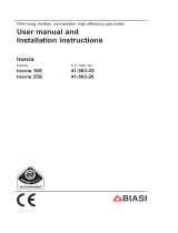
Overview1.1
The model and serial number of the boiler
are printed on bottom right side.
1
2
Fig. 1.1
Controls panel1
House for possible time switch 2
(c.h. control)
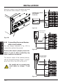
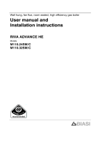
Isolation valves1.2
3
4
5
6
7
8
9
10
11
12
*
Fig. 1.2
Gas supply label3
C.h. circuit pressure gauge4
C.h. fl ow valve5
D.h.w. outlet valve6
Gas inlet valve7
D.c.w. inlet valve8
C.h. return valve9
Condensate drain pipe10
Main circuit drain valve11
C.h. pressure relief valve pipe12
* model and serial number of the boiler
label.

- 9 -
USE
APPLIANCE DESCRIPTION
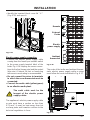
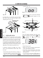
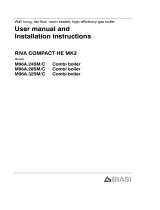
Controls panel1.3
13
14
15
16
17
18
Fig. 1.3
D.h.w. temperature increase key13
D.h.w. temperature reduce key14
Reset/Stand-by/Winter/Summer key15
C.h. temperature reduce key16
C.h. temperature increase key17
LCD display18
RESET that takes all parameters
back to the factory value occurs
only by setting "parameter 08=04".
Reset is displayed by switch on of
all symbols present on the dis-
play.

- 10 -
USE
APPLIANCE DESCRIPTION
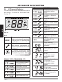
LCD general features1.4
For the boiler technical informations refer to
the section "TECHNICAL INFORMATION"
to page 22 .
Fig. 1.4
RESET
SET
°C
KEY
The symbol indicates that the
boiler can be directly reactivat-
ed by the user, by pressing the
reset button
The symbol indicates that the
fault requires intervention on
behalf of specialised technical
assistance
All symbols represented with
lines that surround them, indi-
cate that the symbol is fl ashing
SIGNAL DISPLAYED BY THE LCD
LCD
FUNCTION
Er 01 +
Lack of burner ignition
on safety lockout
Er 02 +
Safety thermostat
intervention lockout
Er 03 +
General lockout
Er 10 +
Flue probe intervention
lockout
Er 11 +
Flame detection error
LCD
FUNCTION
Er 14 +
Faulty pump or primary
temperature above
105°C
Er 04 +
Faulty primary circuit
(no water or absence
of fl ow)
Er 05 +
Faulty fan control
system
Er 06 +
Faulty c.h. temp. probe
NTC
Er 07 +
Faulty d.h.w. temp.
probe NTC
Er 08 +
Faulty external temp.
probe NTC
Er 09 +
Faulty fl ue temp. probe
NTC
Er 14 +
Absence of fl ow from
temperature gradient
(>2K/s)
Li 01
Primary circuit temp.
limit during D.h.w.
operation
Boiler Stand-By
(anti-freeze protection
activated)
Boiler waiting for heat
request
Boiler in summer mode
(d.h.w.).
The primary circuit
temperature is dis-
played.
Boiler in winter mode
(c.h.+ d.h.w.)
The primary circuit
temperature is dis-
played.
Boiler on demand for
d.h.w. power.
The d.h.w. temperature
is displayed.
Boiler on demand for
c.h. power.

- 11 -
USE
APPLIANCE DESCRIPTION
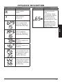
LCD
FUNCTION
Burner ignition
(spark)
Flame present
(Burner on)
Boiler in anti-freeze
phase (bP fl ashing +
temperature fl ashing)
Boiler in antifrost
phase (AF fl ashing +
temperature fl ashing)
Set c.h.
(all other symbols are
disabled)
Set D.h.w.
(all other symbols are
disabled)
Pump activated for the
post-circulation phase
(Po fl ashing + tem-
perature fl ashing)
Delayed burner ignition
for setting the system
(uu fl ashing + tempera-
ture fl ashing)
LCD
FUNCTION
Boiler in chimney
sweep functioning
mode.
The chimney sweep
is activated by setting
"parameter 09=01"
and is visualised by
the switching on of the
hand and alternate
fl ashing between the
temperature and the
communication and
radiator symbol.

- 12 -
USE
INSTRUCTIONS FOR USE
INSTRUCTIONS FOR USE2
Warnings2.1
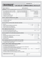
Biasi UK Ltd support the Benchmark
initiative. The Benchmark Log Book is
located at the back of this manual and
should be completed by the Installing/
Commissioning Engineer and handed
over to the User for future reference by
other visiting Engineers.
Also included is the Service Interval
Record card that should be completed
by the Service Engineer following the
annual service maintenance of the boiler
and system.
All Gas Safety Registered Installers car-
ry a Gas Safety ID card, and have a regis-
tration number. Both should be recorded
in your Benchmark Log Book. You can
check your Installer is registered by call-
ing Gas Safety direct on 0800 408 5500,
or go on line at www.GasSafeRegister.
co.uk.
In order to guarantee safety and correct op-
eration, it is essential that all the tests are
carried out by a competent and responsible
service engineer before lighting up the boil-
er.
The tests are described in the installation
instructions in section 7 commissioning.
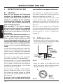
Ensure that the c.h. circuit is regularly fi lled
with water (even if the boiler is only used for
d.h.w. supply) checking that the pressure
indicated on pressure gauge 4 is not lower
than that shown in Fig. 2.2 .
If the pressure reading on the pressure
gauge is below that shown in Fig. 2.2 , then
the system will require topping up.A fi lling
loop is normally provided by the Installer for
this purpose.
If you are in any doubt regarding this
procedure you are advised to contact
your Installer or an Approved Engineer.
This appliance is provided with a built in
anti-freeze system that operates the boiler
when the temperature is below 5 °C.
Therefore, when the boiler is not lit or used
in cold weather, with consequent risk of
freezing do not switch off the boiler at the
fused spur isolation switch or close the gas
inlet cock.
When you do not expect to use the boiler
for a long period and the boiler is not to be
used for frost protection then follow the in-
structions given in section "Extinguishing"
to page 15 .
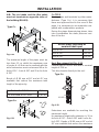
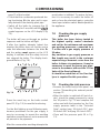
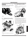
Refi lling procedure2.2
Isolate the boiler from the electrical sup-•
ply at the fused spur. Reconnect the fi lling
loop as demonstrated in Fig. 2.1 .
Fig. 2.1
Control
valve
Double
check valve
Temporary
connection
Supply pipe
(cold water
inlet)
Control valve
C.h. return pipe
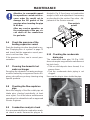
Open the valves of the fi lling loop and •
watch the gauge until it reaches normal
fi lling pressure as shown in Fig. 2.2 .
Fig. 2.2
Normal
fi lling
pressure
4

- 13 -
USE
INSTRUCTIONS FOR USE
If you experience any diffi culty with the
operation of the boiler, switch off the
boiler immediately at the fused spur iso-
lation switch and contact your Installer
or an approved Service Engineer.
Air introduced into the boiler during this fi ll-
ing process will vent through the automatic
air purger fi tted to the boiler. You may also
fi nd it necessary to vent air from your radia-
tor circuit using your radiator key, however
be aware that excessive venting will cause
the pressure in the system to drop.
Always ensure that the pressure gauge is
set at the required pressure.
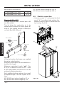
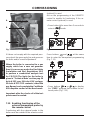
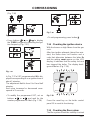
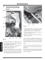
Ignition2.3
Check that the valves located in the lower •
part of the boiler are open Fig. 2.3 .
Fig. 2.3
Open
position
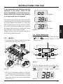
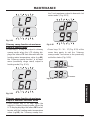
Turn on the electricity supply to the boil-•
er, switching on the fused spur isolation
switch. The LCD display displays the state
within which the boiler is found (last mem-
orised) Fig. 2.4 .
Fig. 2.4
°C
°C
Stand-by
Winter
Summer
C.h. / D.h.w. functioning
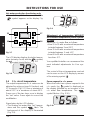
Press the key • 15 for 2 seconds until both
and
symbols appear on the
display
Fig. 2.5 .
Fig. 2.5
13
14
15
16
17
18
The LCD display displays the boiler tem-
perature (primary circuit) and the
and
; symbols; the symbol slowly
fl ashes Fig. 2.6 .
Fig. 2.6
°C

- 14 -
USE
INSTRUCTIONS FOR USE
Hot water production functioning only
Press the key • 15 for 2 seconds until the
symbol appears on the display Fig.
2.7 .
Fig. 2.7
13
14
15
16
17
18
The LCD display displays the boiler temper-
ature (primary circuit) and the
; symbol;
the
symbol slowly fl ashes
Fig. 2.8 .
Fig. 2.8
°C
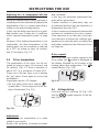
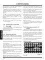
C.h. circuit temperature2.4
The output temperature of c.h. water can be
adjusted by acting on keys 16 (reduce) and
17 (increase) ( Fig. 2.7 ) from a minimum of
about 25°C to a maximum of about 85°C.
Press one of the two keys once to display
the "set" value. Press again to access the
modifi cation.
Signal given by the LCD display:
The heating hot water fl ow "set" temper-•
ature and the symbol
fl ash. The
background of the display is illuminated
( Fig. 2.9 ).
Fig. 2.9
°C
Adjustment of temperature WITHOUT
the external temperature probe (option-
al) fi tted
Adjust the c.h. water fl ow as follows:
from 25 to 35 with an external temperature •
included between 5 and 15°C
from 35 to 60 with an external temperature •
included between -5 and +5°C
from 60 to 85 with an external temperature •
less than -5°C.
Your qualifi ed installer can recommend the
most indicated adjustments for Your sys-
tem.
The control of the set temperature reached
can be seen on the LCD display by means
of the missing symbol
.
Power request in c.h. power.
When the boiler has a power request in the
c.h. mode, the
symbol is displayed on
the display followed by an increase of the
c.h. water fl ow temperature. The
symbol fl ashes ( Fig. 2.10 ).
Fig. 2.10
°C

- 15 -
USE
INSTRUCTIONS FOR USE
Adjusting the c.h. temperature with the
external temp. probe installed
When the external temp. probe (optional) is
installed your boiler automatically adjusts the
temperature of the c.h. system water fl ow in
relation to the external temperature.
In this case the boiler must be set by a quali-
fi ed installer ( see "Setting the K coeffi cient
of the external temperature probe" to page
59 ).
However, if the ambient temperature is not
comfortable, the fl ow temperature of the
heating plant can be increased or reduced
by ± 15°C by acting on keys 16 (reduce)
and 17 (increase) ( Fig. 2.7 ).
D.h.w. temperature2.5
The temperature of the d.h.w. can be ad-
justed by acting on keys 13 (increase) and
14 (reduce) ( Fig. 2.7 ) from a minimum of
about 35°C to a maximum of about 60°C.
Press one of the two keys once to display
the "set" value. Press again to access the
modifi cation.
Signal given by the LCD display:
the "set" value of the d.h.w. and the •
symbol fl ash. The background of the dis-
play is illuminated. ( Fig. 2.9 ).
Fig. 2.11
°C
Adjustment
Adjust the d.h.w. temperature to a value
suited to your needs.
Reduce the necessity of mixing hot water
with cold water.
In this way, the automatic adjustment fea-
tures will be appreciated.
If water hardness is particularly high, we
recommend that the boiler be adjusted to a
temperature less than 50°C.
In these cases we recommend however that
a softener is installed on the d.h.w. system.
If the maximum d.h.w. fl ow rate is too high,
such that does not allow the suffi cient tem-
perature to be reached, have a suitable fl ow
rate limiter installed by the Authorised Serv-
ice Engineer.
D.h.w. request
When the boiler has a power request in the
d.h.w. mode, the
symbol is displayed on
the display followed by an increase of the
heating water fl ow temperature. The
symbol fl ashes ( Fig. 2.12 ).
Fig. 2.12
°C
Extinguishing2.6
Press the key for 2 seconds 15 ( Fig. 2.13 )
until the
symbol appears on the dis-
play ( Fig. 2.14 ).

- 16 -
USE
INSTRUCTIONS FOR USE
Fig. 2.13
13
14
15
16
17
18
Fig. 2.14
If a long period of inactivity is envisioned:
Switch off the electricity supply to the boil-•
er, by means of the fused spur isolation
switch;
Shut off the gas supply cock and the valves •
for the water circuits fi tted under the boiler
Fig. 2.15 ;
Fig. 2.15
Close
position
If necessary, empty the hydraulic circuits •
see section "Emptying the d.h.w. system"
to page 73 and section "Emptying the c.h.
system" to page 73 .

- 17 -
USE
USEFUL ADVICE
USEFUL 3 ADVICE
Central Heating3.1
For reasonably economical service install a
room thermostat. Never shut off the radia-
tor in the area where the room thermostat
is installed.
If a radiator (or a convector) does not heat
up, check that no air is present in it and that
its valve is open. If the ambient temperature
is too high, do not alter the radiator valves.
Reduce the central heating temperature in-
stead by means of the room thermostat or
by acting on the 16 and 17 heating adjust-
ment keys ( Fig. 3.1 ).
Fig. 3.1
13
14
15
16
17
18
Frost protection3.2
The anti-freeze system and any additional
protections protect the boiler from possible
damage due to frost.
This system does not guarantee protection
of the entire hydraulic system.
If the external temperature can reach val-
ues lower than 0°C, it is recommended that
the entire system is activated adjusting the
room thermostat at a low temperature.
The anti-freeze function is also activated
with the boiler in stand-by ( Fig. 3.2 ).
Fig. 3.2
Therefore, when the boiler is not lit and
used in cold weather, with consequent risk
of freezing do not switch off the boiler at the
fused spur isolation switch or close the gas
inlet cock.
If the boiler is deactivated, have a qualifi ed
technician empty the boiler (heating and
domestic hot water circuit), the c.h. system
and the d.h.w. system.
Condensate drain3.3
The condensate drain must not be modi-
fi ed or blocked. Blockage of the condensate
drain, caused by debris or freezing, can
cause automatic shutdown of the boiler. If
freezing is suspected and the pipe run is ac-
cessible an attempt may be made to free
the obstruction by pouring hot water over
the exposed pipe an cleaning any blockage
from the end of the pipe.
If this fails to remedy the problem the as-
sistance of a Gas Safety registered install-
er or in IE a competent person should be
sought.
P3.4 eriodic maintenance
For effi cient and continuous operation of
the boiler, it is advisable to arrange mainte-
nance and cleaning by an Authorised Serv-
ice Centre Engineer, at least once a year.
During the service, the most important
components of the boiler will be inspected

- 18 -
USE
USEFUL ADVICE
and cleaned. This service can be part of a
maintenance contract. In particular, you are
advised to have the following checks car-
ried out:
domestic hot water heat• exchanger;
condensing heat exchanger•
burner;•
exhaust fume duct and fl ue;•
pressurisation of the expansion tank;•
fi lling up of the central heating circuit;•
bleeding of air from the central heating •
system;
general check of the appliance’s opera-•
tion.
External cleaning3.5
Before carrying out any clean-
ing, disconnect the appliance
from the electrical mains, using
the fused spur isolation switch
fi tted adjacent to the appliance.
To clean the external panels, use a cloth
soaked in soapy water. Do not use solvents,
abrasive powders or sponges.
Do not carry out cleaning of the appliance
and/or its parts with readily fl ammable sub-
stances (for example petrol, alcohols, naph-
tha, etc.).
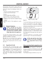
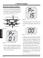
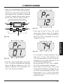
Operational faults3.6
If the boiler does not function and a code
that alternates between the letter Er and the
writing reset (
see "LCD general features" to
page 10
) appear on the LCD display, it indi-
cates that the safety lock-out has stopped
the boiler. The display background fl ashes
( Fig. 3.3 ).
Fig. 3.3
RESET
RESET
For the fi rst lighting up and following main-
tenance procedures for the gas supply, it
may be necessary to repeat the resetting
operation several times so as to remove the
air present in the pipe work.
Safety lock-out may occur even in case of a
blockage of the condensate drainage (e.g.
plugged drain pipe). It is advisable to check
the condensate drainage pipe and traps for
cleanness.
Press the reset key on the boiler control
panel 15 ( Fig. 3.1 ) to reset its functioning.
In this case and in case of per-
sistent lock-out call a competent
and responsible Service Engi-
neer.
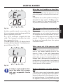
Other operational faults signalled on the
LCD display
If the LCD display displays a code that al-
ternates between the letter Er and the
symbol, the boiler has an anomaly that can-
not be reset.
The display background fl ashes ( Fig. 3.4 ).

- 19 -
USE
USEFUL ADVICE
Fig. 3.4
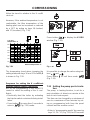
Another possible signal occurs when the
d.h.w. exchanger cannot exchange all of the
power supplied by the boiler.
E.g.: d.h.w. exchanger clogged with lime
scale. This happens only when the boiler
has a request for d.h.w..
Code 01 appears on the LCD display that al-
ternates with the letter Li. The display back-
ground fl ashes ( Fig. 3.5 ).
Fig. 3.5
In order to reset good function-
ing of the boiler, call a compe-
tent and responsible Service
Engineer.
Noise due to air bubbles are heard dur-
ing operation
You should check that the pressure on the
pressure gauge is not below the correct set-
ting.
If required, top up the system correctly, as
described in the section "Refi lling proce-
dure" to page 12 of this manual. Bleed any
air present in the radiators, if necessary.
The pressure on the pressure gauge has
gone down
It is necessary to top up the appliance with
water again, so as to raise the pressure to
an adequate level as described in the
sec-
tion "Refi lling procedure" to page 12
of this
manual. If topping up with water has to
be done very frequently, have the system
checked for leaks.
Water comes out of the pressure relief
valve
Check on the pressure gauge that the pres-
sure in the central heating circuit is not
close to 3 bars. In this case, temperature
rise in the circuit can cause the pressure
relief valve to open. So that this does not
happen and to decrease the pressure to a
normal value, it is advisable to vent some of
the water in the appliance through the bleed
valves present in the radiators.
Reduced domestic hot water tempera-
ture
The likely causes may be impurities caught
in the domestic hot water fl ow switch fi lter or
limescale deposited in the domestic hot wa-
ter heat exchanger. It is advisable to have
the appliance cleaned out by an Authorised

- 20 -
USE
USEFUL ADVICE
Service Centre Engineer.
Water should occasionally leak from the
boiler
Shut off the valves positioned under the
boiler to page
16
and call an Authorised
Service Centre Engineer.
In this case or in case of prob-
lems other than those men-
tioned here, switch off the boiler,
as described in section "Extin-
guishing" to page 15 and call a
competent and responsible
Service Engineer.
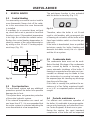
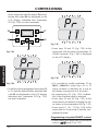
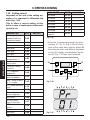
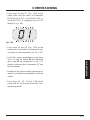
Displaying in INFO mode3.7
The INFO mode allows the display of some
information on the boiler functioning status.
In case of malfunctioning of the boiler, it may
be useful to communicate such information
to the Authorised Service Centre Engineer
so that the causes can be understood.
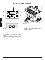
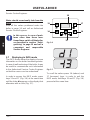
In order to access the INFO mode, press
keys 15 and 17 ( Fig. 3.6 ) at the same time
until the letter di appears on the display that
alternates with a code ( Fig. 3.7 ).
Fig. 3.6
13
14
15
16
17
18
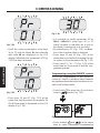
Fig. 3.7
To scroll the values press 16 (reduce) and
17 (increase). keys. In order to exit the
INFO mode, hold keys 15 and 17 ( Fig. 3.6 )
pressed at the same time.
Page is loading ...
Page is loading ...
Page is loading ...
Page is loading ...
Page is loading ...
Page is loading ...
Page is loading ...
Page is loading ...
Page is loading ...
Page is loading ...
Page is loading ...
Page is loading ...
Page is loading ...
Page is loading ...
Page is loading ...
Page is loading ...
Page is loading ...
Page is loading ...
Page is loading ...
Page is loading ...
Page is loading ...
Page is loading ...
Page is loading ...
Page is loading ...
Page is loading ...
Page is loading ...
Page is loading ...
Page is loading ...
Page is loading ...
Page is loading ...
Page is loading ...
Page is loading ...
Page is loading ...
Page is loading ...
Page is loading ...
Page is loading ...
Page is loading ...
Page is loading ...
Page is loading ...
Page is loading ...
Page is loading ...
Page is loading ...
Page is loading ...
Page is loading ...
Page is loading ...
Page is loading ...
Page is loading ...
Page is loading ...
Page is loading ...
Page is loading ...
Page is loading ...
Page is loading ...
Page is loading ...
Page is loading ...
Page is loading ...
Page is loading ...
Page is loading ...
Page is loading ...
Page is loading ...
Page is loading ...
-
 1
1
-
 2
2
-
 3
3
-
 4
4
-
 5
5
-
 6
6
-
 7
7
-
 8
8
-
 9
9
-
 10
10
-
 11
11
-
 12
12
-
 13
13
-
 14
14
-
 15
15
-
 16
16
-
 17
17
-
 18
18
-
 19
19
-
 20
20
-
 21
21
-
 22
22
-
 23
23
-
 24
24
-
 25
25
-
 26
26
-
 27
27
-
 28
28
-
 29
29
-
 30
30
-
 31
31
-
 32
32
-
 33
33
-
 34
34
-
 35
35
-
 36
36
-
 37
37
-
 38
38
-
 39
39
-
 40
40
-
 41
41
-
 42
42
-
 43
43
-
 44
44
-
 45
45
-
 46
46
-
 47
47
-
 48
48
-
 49
49
-
 50
50
-
 51
51
-
 52
52
-
 53
53
-
 54
54
-
 55
55
-
 56
56
-
 57
57
-
 58
58
-
 59
59
-
 60
60
-
 61
61
-
 62
62
-
 63
63
-
 64
64
-
 65
65
-
 66
66
-
 67
67
-
 68
68
-
 69
69
-
 70
70
-
 71
71
-
 72
72
-
 73
73
-
 74
74
-
 75
75
-
 76
76
-
 77
77
-
 78
78
-
 79
79
-
 80
80


Biasi ActivA 25C, 30C, 35C User manual
- Category
- Water heaters & boilers
- Type
- User manual
- This manual is also suitable for
Ask a question and I''ll find the answer in the document
Finding information in a document is now easier with AI
Related papers
-
Biasi Advance Plus 25S, 30S User manual
-
 Biasi Garda Plus M110B.24SM/E, M110B.32SM/E User manual
-
Biasi Advance Plus 25C, 30C, 35C User manual
-
 Biasi Riva Advance M110B.24SM/C, M110B.32SM/C User manual
-
 Biasi Advance System User manual
-
 Biasi Garda Plus M110.24SM/E, M110.32SM/E User manual
-
 Biasi Inovia 25S User manual
-
 Biasi Advance 25C User manual
-
 Biasi Riva Advance M110.24SM/C, M110.32SM/C User manual
-
 Biasi M96A.28SM/B User manual


Other documents
-
 De Dietrich User instruction card User guide
-
 Riva PLUS COMBI Installation & Operation Instructions
-
 Protherm 23 BTVE User, Installation And Servicing Instructions
-
Sime Murelle EV Installation guide
-
-
-
-
-
-


