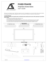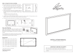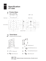
Hardware Parts List
Note: The Parts list above is subject to change without notice.
Rev. 061518-BR www.akiascreens.com 1
Care & Use Intructions
a. Spring b. Spring Hook c. Allen wrench
d. Elbow Joints e. Center Joints f. Hollow Wall Anchors
g. Top/Bottom Wall Brackets h. Center Support Bar i. Tension Rods
j. M5x40 Screws k. M4x12 Screws m. Screwdriver
Thank you for choosing the Fixed Frame Series projection screen! Please read through this user guide before utilizing the
screen. Correct usage and maintenance will ensure a long product life.
Dust, dirt and scratches on the projection surface will affect the picture quality, please take note of the points below to
prevent that from occurring:
1. Do not touch the projection surface with your hands
2. Do not write or draw on the projection surface
3. Do not use fingers or sharp objects to point on the projection surface; this will damage the screen material.
4. Use a soft-damp cloth to clean the projection surface; do not use chemical cleaning agents or alcohol.
5. Use clean water when dampening the cleaning cloth and do not rub against the material to clean it.
l. M5x12 Screw
Fixed-Frame Projection Screen
User’s Guide
Fixed Frame Series

Frame Assembly
Step 1. Place a soft-clean cloth on the ground or other flat surface of the area where the screen will be assembled.
Step 2. Position the pieces of the frame face-down on the soft-clean cloth in the arrangement shown below.
Rev. 061518-BR www.akiascreens.com 2
Parts List
Main Frame Parts
Vertical Frame
1/2 Horizontal Frame
1/2 Horizontal Frame
Edge Trim Parts
Qty
Item
2 pcs
2 pcs
2 pcs
2 pcs
2 pcs
Qty
Item
125”
Spring 48
Spring Hook 1
1
Allen Wrench 1
Elbow Joints
Center Joints 4
Hollow Wall Anchors 4
Wall Brackets 6
Center Support Bar
M4x12 Screws
M5x12 Screws
4
12
Tension Rods 6
M5x40 Screws 4
8
Item
Frame and Edge Trim Parts List
a.
b.
c.
d.
e.
f.
g.
h.
i.
j.
k.
l.
100”
38
1
1
1
4
4
6
4
12
6
4
8
1 1Screwdriverm.

Step 4. After connecting the center joints (e), insert 3 brackets (g) on each of the horizontal frames (top and bottom).
Refer to the diagram below for bracket (g) placement. Note: The top and bottom center brackets will be used to secure
the center support bar.
NOTE: Make sure to complete step 4 before moving forward with the frame assembly. Failure to do so may result
in disassembly of the screen to repeat the step.
Step 5. Connect the Elbow Joints (d) to top and bottom sections of the vertical frame. Once inserted, connect the
vertical sections to the horizontal frame sections. Make sure all the holes are in alignment and the frame pieces are
flush (no gaps). They should form perfect right angles. NOTE: Do not tighten elbow joints completely until all
frame pieces are assembled correctly.
www.akiascreens.comRev. 061518-BR 3
Step 3. Insert the Center Joint (e) connectors into one-half
of the horizontal frame and secure with two screws. Once
secure, connect the other half of the horizontal frame and
fasten with two screws. NOTE: Make sure to insert 3
brackets (g) on each of the horizontal frames (Top and
bottom) after connecting the center joints.

www.akiascreens.comRev. 061518-BR 4
Screen Material Installation
Step 1. Lay the screen material completely flat with the front facing down on a clean surface in a horizontal position.
The back side of the screen material should be placed upwards.
Step 2. Carefully and gently place the assembled frame on top the screen material as shown below. Make sure to not
allow the angle edge of the frame to come in direct contact with the screen material to avoid puncturing it.
Back Side
Center Support Bar
Hook bigger spring
head to material
Step 3. Insert the four horizontal and two vertical Tension
Rods (i) into the corresponding sides of the screen material,
while keeping the material laying flat. Careful not to snag
on the holes at the edge of the material during this process;
forcing the rods may damage the screen material.
Step 1. Two people are suggested for this step. Place the Center Support Bar (h) into the top groove of the back of
the frame aligning it with the center bracket. Next, slowly push the opposite side of the center support bar towards the
other center bracket as shown below.
Step 4. After the tension rods have been inserted, make
sure to have all corners aligned to the frame and fold over
the material on each corner. NOTE: Make sure to stretch
the material tightly over the frame to maintain a flat
surface.
Step 5. Starting from all four corners, hook the Springs (a)
through the hole located on the screen material’s outer
edge. First, hook the small spring head to the frame. Then
using the Spring hook (b), hook the other side of the spring
to the material. NOTE: Only do the corners for this step.
Hook small spring
head to frame

www.akiascreens.com 5Rev. 061518-BR
Step 1. Locate your desired installation location and meas-
ure the distance between the top and bottom bracket holes
on the frame. Next, Mark the drill-hole area of where the
screen is to be installed as shown.
Step 2. Using the marked area, drill holes on the wall and
keep a 5mm distance outside. NOTE: This is where the
brackets will be placed.
Step 2. Make sure to secure the corner and center M5x12 screws (l) of the velvet frame.
Velvet Frame Installation
Step 1. Place the velvet frame pieces over each side of the
frame and secure it using the M5x12 screws(l). NOTE: Do
not completely tighten the screws until you make sure each
corner forms a right angle.
Wall Installation
Step 2. Once the support bar is centered and secured, hook the remainder of the Springs working your way from the
center. Lastly, insert the M4x12 screws (k) to the center support bar (h) and tighten.
Wall

www.akiascreens.com 6Rev. 061518-BR
For Technical support or an Akia™ Screens contact in your area, visit
www.akiascreens.com
Step 3. Place the wall anchor (f) followed by an M5x40 screw (j) to the wall for each bracket on the frame. Next,
using two people, carefully position the screen onto the wall. Your installation is now complete.
In rare instances you may see creases or memory lines on the material surface after installation. In order to resolve this, keep the
screen in a warm room environment (above 75 degrees) for a few days. This allows the material to stretch out and cure itself. After
a few days, the creases should vanish and the material should be alleviated.
Disclaimer
/


