Danfoss VLT AQUA Drive FC 202 User guide

Type
User guide
ENGINEERING TOMORROW
Design Guide
VLT
®
AQUA Drive FC 202
110–800 kW, Enclosure Sizes D and E
vlt-drives.danfoss.com
Contents
1 Introduction
5
1.1 Purpose of the Design Guide
5
1.2 Additional Resources
5
1.3 Document and Software Version
5
1.4 Conventions
5
2 Safety
6
2.1 Safety Symbols
6
2.2 Qualied Personnel
6
2.3 Safety Precautions
6
3 Approvals and Certications
8
3.1 Regulatory/Compliance Approvals
8
3.2 Enclosure Protection Ratings
10
4 Product Overview
12
4.1 VLT
®
High-power Drives
12
4.2 Enclosure Size by Power Rating
12
4.3 Overview of Enclosures, 380–500 V
13
4.4 Overview of Enclosures, 525–690 V
15
4.5 Kit Availability
17
5 Product Features
18
5.1 Automated Operational Features
18
5.2 Custom Application Features
20
5.3 Specic VLT
®
AQUA Drive FC 202 Features
24
5.4 Cascade Control Overview
25
5.5 Basic Cascade Controller Overview
27
5.6 Deragging Overview
28
5.7 Pre/post Lube Overview
29
5.8 Flow Conrmation Overview
30
5.9 Advanced Minimum Speed Monitoring Overview
30
5.10 Dynamic Braking Overview
31
5.11 Load Share Overview
31
5.12 Regen Overview
32
5.13 Back-channel Cooling Overview
33
6 Options and Accessories Overview
35
6.1 Fieldbus Devices
35
6.2 Functional Extensions
35
6.3 Motion Control and Relay Cards
36
Contents Design Guide
MG22B202 Danfoss A/S © 01/2018 All rights reserved. 1
6.4 Brake Resistors
37
6.5 Sine-wave Filters
37
6.6 dU/dt Filters
37
6.7 Common-mode Filters
37
6.8 Harmonic Filters
37
6.9 High-power Kits
37
7 Specications
38
7.1 Electrical Data, 380–480 V
38
7.2 Electrical Data, 525–690 V
42
7.3 Mains Supply
49
7.4 Motor Output and Motor Data
49
7.5 Ambient Conditions
49
7.6 Cable Specications
50
7.7 Control Input/Output and Control Data
50
7.8 Enclosure Weights
53
8 Exterior and Terminal Dimensions
54
8.1 D1h Exterior and Terminal Dimensions
54
8.2 D2h Exterior and Terminal Dimensions
60
8.3 D3h Exterior and Terminal Dimensions
66
8.4 D4h Exterior and Terminal Dimensions
71
8.5 D5h Exterior and Terminal Dimensions
76
8.6 D6h Exterior and Terminal Dimensions
85
8.7 D7h Exterior and Terminal Dimensions
96
8.8 D8h Exterior and Terminal Dimensions
106
8.9 E1h Exterior and Terminal Dimensions
117
8.10 E2h Exterior and Terminal Dimensions
123
8.11 E3h Exterior and Terminal Dimensions
129
8.12 E4h Exterior and Terminal Dimensions
136
9 Mechanical Installation Considerations
143
9.1 Storage
143
9.2 Lifting the Unit
143
9.3 Operating Environment
143
9.4 Mounting Congurations
144
9.5 Cooling
145
9.6 Derating
145
10 Electrical Installation Considerations
149
10.1 Safety Instructions
149
10.2 Wiring Schematic
150
Contents
VLT
®
AQUA Drive FC 202
2 Danfoss A/S © 01/2018 All rights reserved. MG22B202
10.3 Connections
151
10.4 Control Wiring and Terminals
152
10.5 Fuses and Circuit Breakers
156
10.6 Motor
158
10.7 Braking
160
10.8 Residual Current Devices (RCD) and Insulation Resistance Monitor (IRM)
163
10.9 Leakage Current
163
10.10 IT Mains
164
10.11 Eciency
164
10.12 Acoustic Noise
165
10.13 dU/dt Conditions
165
10.14 Electromagnetic Compatibility (EMC) Overview
171
10.15 EMC-compliant Installation
174
10.16 Harmonics Overview
177
11 Basic Operating Principles of a Drive
180
11.1 Description of Operation
180
11.2 Drive Controls
180
12 Application Examples
189
12.1 Wiring Congurations for Automatic Motor Adaptation (AMA)
189
12.2 Wiring Congurations for Analog Speed Reference
189
12.3 Wiring Congurations for Start/Stop
190
12.4 Wiring Conguration for an External Alarm Reset
191
12.5 Wiring Conguration for Speed Reference Using a Manual Potentiometer
192
12.6 Wiring Conguration for Speed Up/Speed Down
192
12.7 Wiring Conguration for RS485 Network Connection
193
12.8 Wiring Conguration for a Motor Thermistor
193
12.9 Wiring Conguration for a Relay Set-up with Smart Logic Control
194
12.10 Wiring Conguration for a Submersible Pump
194
12.11 Wiring Conguration for a Cascade Controller
196
12.12 Wiring Conguration for a Fixed Variable Speed Pump
197
12.13 Wiring Conguration for Lead Pump Alternation
197
13 How to Order a Drive
198
13.1 Drive Congurator
198
13.2 Ordering Numbers for Options and Accessories
201
13.3 Ordering Numbers for Filters and Brake Resistors
205
13.4 Spare Parts
205
14 Appendix
206
14.1 Abbreviations and Symbols
206
Contents Design Guide
MG22B202 Danfoss A/S © 01/2018 All rights reserved. 3
14.2 Denitions
207
Index
208
Contents
VLT
®
AQUA Drive FC 202
4 Danfoss A/S © 01/2018 All rights reserved. MG22B202
1 Introduction
1.1 Purpose of the Design Guide
This design guide is intended for:
Project and systems engineers.
Design consultants.
Application and product specialists.
The design guide provides technical information to
understand the capabilities of the drive for integration into
motor control and monitoring systems.
VLT
®
is a registered trademark.
1.2 Additional Resources
Other resources are available to understand advanced
drive operation, programming, and directives compliance.
The operating guide provides detailed information
for the installation and start-up of the drive.
The programming guide provides greater detail on
how to work with parameters and includes many
application examples.
The VLT
®
FC Series - Safe Torque O Operating
Guide describes how to use Danfoss drives in
functional safety applications. This manual is
supplied with the drive when the Safe Torque O
option is present.
The VLT
®
Brake Resistor MCE 101 Design Guide
describes how to select the optimal brake resistor.
The VLT
®
Advanced Harmonic Filters AHF 005/AHF
010 Design Guide describes harmonics, various
mitigation methods, and the operating principle
of the advanced harmonics lter. This guide also
describes how to select the correct advanced
harmonics lter for a particular application.
The Output Filters Design Guide explains why it is
necessary to use output lters for certain
applications, and how to select the optimal dU/dt
or sine-wave lter.
Optional equipment is available that can change
some of the information described in these
publications. For specic requirements, see the
instructions supplied with the options.
Supplementary publications and manuals are available
from Danfoss. See drives.danfoss.com/downloads/portal/#/
for listings.
1.3
Document and Software Version
This manual is regularly reviewed and updated. All
suggestions for improvement are welcome. Table 1.1 shows
the document version and the corresponding software
version.
Edition Remarks Software version
MG22B2xx Added D1h–D8h content 3.10
Table 1.1 Document and Software Version
1.4 Conventions
Numbered lists indicate procedures.
Bullet lists indicate other information and
description of illustrations.
Italicized text indicates:
- Cross-reference.
- Link.
- Footnote.
- Parameter name, parameter group
name, parameter option.
All dimensions in drawings are in mm (in).
An asterisk (*) indicates a default setting of a
parameter.
Introduction Design Guide
MG22B202 Danfoss A/S © 01/2018 All rights reserved. 5
1 1
2 Safety
2.1 Safety Symbols
The following symbols are used in this guide:
WARNING
Indicates a potentially hazardous situation that could
result in death or serious injury.
CAUTION
Indicates a potentially hazardous situation that could
result in minor or moderate injury. It can also be used to
alert against unsafe practices.
NOTICE
Indicates important information, including situations that
can result in damage to equipment or property.
2.2 Qualied Personnel
Only qualied personnel are allowed to install or operate
this equipment.
Qualied personnel are dened as trained sta, who are
authorized to install, commission, and maintain equipment,
systems, and circuits in accordance with pertinent laws and
regulations. Also, the personnel must be familiar with the
instructions and safety measures described in this manual.
2.3
Safety Precautions
WARNING
HIGH VOLTAGE
Drives contain high voltage when connected to AC mains
input, DC supply, load sharing, or permanent motors.
Failure to use qualied personnel to install, start up, and
maintain the drive can result in death or serious injury.
Only qualied personnel must install, start up,
and maintain the drive.
WARNING
DISCHARGE TIME
The drive contains DC-link capacitors, which can remain
charged even when the drive is not powered. High
voltage can be present even when the warning LED
indicator lights are o. Failure to wait for the specied
amount of time listed in Table 2.1 after power has been
removed before performing service or repair work can
result in death or serious injury.
1. Stop the motor.
2. Disconnect AC mains and remote DC-link
supplies, including battery back-ups, UPS, and
DC-link connections to other drives.
3. Disconnect or lock motor.
4. Wait for the capacitors to discharge fully. Refer
to Table 2.1.
5. Before performing any service or repair work,
use an appropriate voltage measuring device to
make sure that the capacitors are fully
discharged.
Voltage Power rating
(normal overload)
Enclosure Minutes to disharge
380–480 110–315 kW
150–450 hp
D1h–D8h 20
380–480 355–560 kW
500–750 hp
E1h–E4h 40
525–690 75–400 kW
75–400 hp
D1h–D8h 20
525–690 450–800 kW
450–950 hp
E1h–E4h 40
Table 2.1 Discharge Time for Enclosures D1h–D8h and E1h–E4h
WARNING
LEAKAGE CURRENT HAZARD
Leakage currents exceed 3.5 mA. Failure to ground the
drive properly can result in death or serious injury.
Ensure the correct grounding of the equipment
by a certied electrical installer.
NOTICE
MAINS SHIELD SAFETY OPTION
A mains shield option is available for enclosures with a
protection rating of IP21/IP54 (Type 1/Type 12). The
mains shield is a cover installed inside the enclosure to
protect against the accidental touch of the power
terminals, according to BGV A2, VBG 4.
Safety
VLT
®
AQUA Drive FC 202
6 Danfoss A/S © 01/2018 All rights reserved. MG22B202
22
2.3.1 ADN-compliant Installation
To prevent spark formation in accordance with the
European Agreement concerning International Carriage of
Dangerous Goods by Inland Waterways (ADN), take
precautions for drives with protection rating of IP00
(Chassis), IP20 (Chassis), IP21 (Type 1), or IP54 (Type 12).
Do not install a mains switch.
Ensure that parameter 14-50 RFI Filter is set to
[1] On.
Remove all relay plugs marked RELAY. See
Illustration 2.1.
Check which relay options are installed, if any.
The only allowed relay option is VLT
®
Extended
Relay Card MCB 113.
1
2
e30bd832.10
1, 2 Relay plugs
Illustration 2.1 Location of Relay Plugs
Safety Design Guide
MG22B202 Danfoss A/S © 01/2018 All rights reserved. 7
2 2
3 Approvals and Certications
This section provides a brief description of the various
approvals and certications that are found on Danfoss
drives. Not all approvals are found on all drives.
3.1 Regulatory/Compliance Approvals
NOTICE
IMPOSED LIMITATIONS ON THE OUTPUT
FREQUENCY
From software version 1.99 onwards, the output
frequency of the drive is limited to 590 Hz due to export
control regulations.
3.1.1.1 CE Mark
The CE mark (Communauté Européenne) indicates that the
product manufacturer conforms to all applicable EU
directives. The EU directives applicable to the design and
manufacture of drives are listed in Table 3.1.
NOTICE
The CE mark does not regulate the quality of the
product. Technical specications cannot be deduced from
the CE mark.
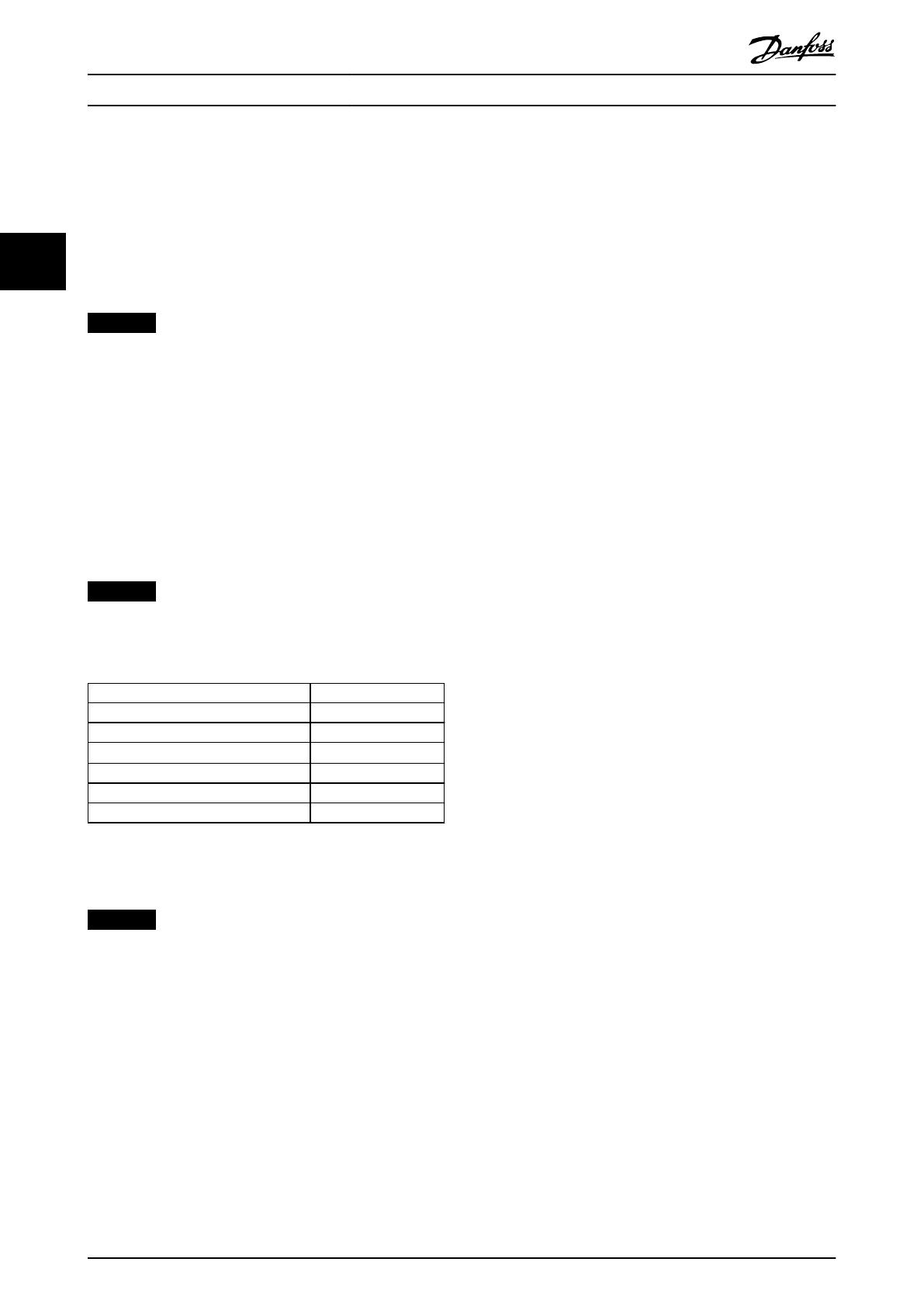
EU Directive Version
Low Voltage Directive 2014/35/EU
EMC Directive 2014/30/EU
Machinery Directive
1)
2014/32/EU
ErP Directive 2009/125/EC
ATEX Directive 2014/34/EU
RoHS Directive 2002/95/EC
Table 3.1 EU Directives Applicable to Drives
1) Machinery Directive conformance is only required for drives with
an integrated safety function.
NOTICE
Drives with an integrated safety function, such as Safe
Torque O (STO), must comply with the Machinery
Directive.
Declarations of conformity are available on request.
Low Voltage Directive
Drives must be CE-labeled in accordance with the Low
Voltage Directive of January 1, 2014. The Low Voltage
Directive applies to all electrical equipment in the 50–
1000 V AC and the 75–1500 V DC voltage ranges.
The aim of the directive is to ensure personal safety and
avoid property damage when operating electrical
equipment that is installed, maintained, and used as
intended.
EMC Directive
The purpose of the EMC (electromagnetic compatibility)
Directive is to reduce electromagnetic interference and
enhance immunity of electrical equipment and instal-
lations. The basic protection requirement of the EMC
Directive is that devices that generate electromagnetic
interference (EMI), or whose operation can be aected by
EMI, must be designed to limit the generation of electro-
magnetic interference. The devices must have a suitable
degree of immunity to EMI when properly installed,
maintained, and used as intended.
Electrical equipment devices used alone or as part of a
system must bear the CE mark. Systems do not require the
CE mark, but must comply with the basic protection
requirements of the EMC Directive.
Machinery Directive
The aim of the Machinery Directive is to ensure personal
safety and avoid property damage to mechanical
equipment used in its intended application. The Machinery
Directive applies to a machine consisting of an aggregate
of interconnected components or devices of which at least
1 is capable of mechanical movement.
Drives with an integrated safety function must comply with
the Machinery Directive. Drives without a safety function
do not fall under the Machinery Directive. If a drive is
integrated into a machinery system, Danfoss can provide
information on safety aspects relating to the drive.
When drives are used in machines with at least 1 moving
part, the machine manufacturer must provide a declaration
stating compliance with all relevant statutes and safety
measures.
3.1.1.2 ErP Directive
The ErP Directive is the European Ecodesign Directive for
energy-related products, including drives. The aim of the
directive is to increase energy eciency and the level of
protection of the environment, while increasing the
security of the energy supply. Environmental impact of
energy-related products includes energy consumption
throughout the entire product life cycle.
3.1.1.3 UL Listing
The Underwriters Laboratory (UL) mark certies the safety
of products and their environmental claims based on
standardized testing. Drives of voltage T7 (525–690 V) are
UL-certied for only 525–600 V. The drive complies with UL
61800-5-1 thermal memory retention requirements. For
more information, refer to chapter 10.6.1 Motor Thermal
Protection.
Approvals and Certication...
VLT
®
AQUA Drive FC 202
8 Danfoss A/S © 01/2018 All rights reserved. MG22B202
33
3.1.1.4 CSA/cUL
The CSA/cUL approval is for AC drives of voltage rated at
600 V or lower. The standard ensures that, when the drive
is installed according to the provided operating/installation
guide, the equipment meets the UL standards for electrical
and thermal safety. This mark certies that the product
performs to all required engineering specications and
testing. A certicate of compliance is provided on request.
3.1.1.5 EAC
The EurAsian Conformity (EAC) mark indicates that the
product conforms to all requirements and technical
regulations applicable to the product per the EurAsian
Customs Union, which is composed of the member states
of the EurAsian Economic Union.
The EAC logo must be both on the product label and on
the packaging label. All products used within the EAC area,
must be bought at Danfoss inside the EAC area.
3.1.1.6 UKrSEPRO
UKrSEPRO certicate ensures quality and safety of both
products and services, in addition to manufacturing
stability according to Ukrainian regulatory standards. The
UkrSepro certicate is a required document to clear
customs for any products coming into and out of the
territory of Ukraine.
3.1.1.7 TÜV
TÜV SÜD is a European safety organization which certies
the functional safety of the drive in accordance to EN/IEC
61800-5-2. The TÜV SÜD both tests products and monitors
their production to ensure that companies stay compliant
with their regulations.
3.1.1.8 RCM
The Regulatory Compliance Mark (RCM) indicates
compliance with telecommunications and EMC/radio-
communications equipment per the Australian
Communications and Media Authorities EMC labeling
notice. RCM is now a single compliance mark covering
both the A-Tick and the C-Tick compliance marks. RCM
compliance is required for placing electrical and electronic
devices on the market in Australia and New Zealand.
3.1.1.9 Marine
Marine applications - ships and oil/gas platforms - must be
certied by 1 of more marine certication societies to
receive a regulatory license and insurance. Danfoss VLT
®
AQUA Drive series drives are certied by up to 12 dierent
marine classication societies.
To view or print marine approvals and certicates, go to
the download area at drives.danfoss.com/industries/marine-
and-oshore/marine-type-approvals/#/.
3.1.2 Export Control Regulations
Drives can be subject to regional and/or national export
control regulations.
An ECCN number is used to classify all drives that are
subject to export control regulations. The ECCN number is
provided in the documents accompanying the drive.
In case of re-export, it is the responsibility of the exporter
to ensure compliance with the relevant export control
regulations.
Approvals and Certication... Design Guide
MG22B202 Danfoss A/S © 01/2018 All rights reserved. 9
3 3
3.2 Enclosure Protection Ratings
The VLT
®
drive series are available in various enclosure protection to accommodate the needs of the application. Enclosure
protection ratings are provided based on 2 international standards:
UL type validates that the enclosures meet NEMA (National Electrical Manufacturers Association) standards. The
construction and testing requirements for enclosures are provided in NEMA Standards Publication 250-2003 and UL
50, Eleventh Edition.
IP (Ingress Protection) ratings outlined by IEC (International Electrotechnical Commission) in the rest of the world.
Standard Danfoss VLT
®
drive series are available in various enclosure protections to meet the requirements of IP00 (Chassis),
IP20 (Protected chassis) or IP21 (UL Type 1), or IP54 (UL Type 12). In this manual, UL Type is written as Type. For example,
IP21/Type 1.
UL type standard
Type 1 Enclosures constructed for indoor use to provide a degree of protection to personnel against incidental contact
with the enclosed units and to provide a degree of protection against falling dirt.
Type 12 General-purpose enclosures are intended for use indoors to protect the enclosed units against the following:
Fibers
Lint
Dust and dirt
Light splashing
Seepage
Dripping and external condensation of noncorrosive liquids
There can be no holes through the enclosure and no conduit knockouts or conduit openings, except when used with oil-
resistant gaskets to mount oil-tight or dust-tight mechanisms. Doors are also provided with oil-resistant gaskets. In addition,
enclosures for combination controllers have hinged doors, which swing horizontally and require a tool to open.
IP standard
Table 3.2 provides a cross-reference between the 2 standards. Table 3.3 demonstrates how to read the IP number and then
denes the levels of protection. The drives meet the requirements of both.
NEMA and UL IP
Chassis IP00
Protected chassis IP20
Type 1 IP21
Type 12 IP54
Table 3.2 NEMA and IP Number Cross-reference
Approvals and Certication...
VLT
®
AQUA Drive FC 202
10 Danfoss A/S © 01/2018 All rights reserved. MG22B202
33
1
st
digit 2
nd
digit
Level of protection
0 No protection.
1 Protected to 50 mm (2.0 in). No hands would be able to get into the enclosure.
2 Protected to 12.5 mm (0.5 in). No ngers would be able to get into the enclosure.
3 Protected to 2.5 mm (0.1 in). No tools would be able to get into the enclosure.
4 Protected to 1.0 mm (0.04 in). No wires would be able to get into the enclosure.
5 Protected against dust limited entry.
6 Protected totally against dust.
0 No protection.
1 Protected from vertical dripping water.
2
Protected from dripping water at 15° angle.
3
Protected from water at 60° angle.
4 Protected from splashing water.
5 Protected from water jets.
6 Protected from strong water jets.
7 Protected from temporary immersion.
8 Protected from permanent immersion.
Table 3.3 IP Number Breakdown
Approvals and Certication... Design Guide
MG22B202 Danfoss A/S © 01/2018 All rights reserved. 11
3 3
4 Product Overview
4.1
VLT
®
High-power Drives
The Danfoss VLT
®
drives described in this manual are available as free-standing, wall-mounted, or cabinet-mounted units.
Each VLT
®
drive is congurable, compatible, and eciency-optimized for all standard motor types, which avoids the
restrictions of motor-drive package deals.
Benets of VLT
®
Drives
Available in various enclosure sizes and protection ratings.
98% eciency reduces operating costs.
Unique back-channel cooling design reduces the need for more cooling equipment, resulting in lower installation
and recurring costs.
Lower power consumption for control room cooling equipment.
Reduced ownership costs.
Consistent user interface across the entire range of Danfoss drives.
Application-oriented start-up wizards.
Multi-language user interface.
4.2 Enclosure Size by Power Rating
kW
1)
Hp
1)
Available enclosures
110 150 D1h/D3h/D5h/D6h
132 200 D1h/D3h/D5h/D6h
160 250 D1h/D3h/D5h/D6h
200 300 D2h/D4h/D7h/D8h
250 350 D2h/D4h/D7h/D8h
315 450 D2h/D4h/D7h/D8h
355 500 E1h/E3h
400 600 E1h/E3h
450 600 E1h/E3h
500 650 E2h/E4h
560 750 E2h/E4h
Table 4.1 Enclosure Power Ratings, 380–480 V
1) All power ratings are taken at normal overload.
Output is measured at 400 V (kW) and 460 V (hp).
kW
1)
Hp
1)
Available enclosures
75 75 D1h/D3h/D5h/D6h
90 100 D1h/D3h/D5h/D6h
110 125 D1h/D3h/D5h/D6h
132 150 D1h/D3h/D5h/D6h
160 200 D1h/D3h/D5h/D6h
200 250 D2h/D4h/D7h/D8h
250 300 D2h/D4h/D7h/D8h
315 350 D2h/D4h/D7h/D8h
400 400 D2h/D4h/D7h/D8h
450 450 E1h/E3h
500 500 E1h/E3h
560 600 E1h/E3h
630 650 E1h/E3h
710 750 E2h/E4h
800 950 E2h/E4h
Table 4.2 Enclosure Power Ratings, 525–690 V
1) All power ratings are taken at normal overload.
Output is measured at 690 V (kW) and 575 V (hp).
Product Overview
VLT
®
AQUA Drive FC 202
12 Danfoss A/S © 01/2018 All rights reserved. MG22B202
44
4.3 Overview of Enclosures, 380–500 V
Enclosure size D1h D2h D3h D4h D5h D6h D7h D8h
Power rating
1)
Output at 400 V (kW) 110–160 200–315 110–160 200–315 110–160 110–160 200–315 200–315
Output at 460 V (hp) 150–250 300–450 150–250 300–450 150–250 150–250 300–450 300–450
Protection rating
IP IP21/54 IP21/54 IP20 IP20 IP21/54 IP21/54 IP21/54 IP21/54
NEMA Type 1/12 Type 1/12 Type Chassis Type Chassis Type 1/12 Type 1/12 Type 1/12 Type 1/12
Hardware options
2)
Stainless steel back
channel
O O O O O O O O
Mains shielding O O O O O O
Space heater O O O O O O
RFI lter (Class A1) O O O O O O O O
Safe torque o S S S S S S S S
No LCP O O O O O O O O
Numerical LCP O O O O O O O O
Graphical LCP O O O O O O O O
Fuses O O O O O O O O
Heat sink access
3)
O O O O O O O O
Brake chopper O O O O O O
Regeneration terminals O O O O O O
Loadshare terminals O O
Fuses + loadshare O O
Disconnect O O
Circuit breakers O O
Contactors O O
24 V DC supply O O O O O O O O
Dimensions
Height, mm (in) 901 (35.5) 1107 (43.6) 909 (35.8)
1004 (39.5)
4)
1027 (40.4)
1027 (40.4)
4)
1324 (52.1) 1663 (65.5) 1978 (77.9) 2284 (89.9)
Width, mm (in) 325 (12.8) 325 (12.8) 250 (9.8) 375 (14.8) 325 (12.8) 325 (12.8) 420 (16.5) 420 (16.5)
Depth, mm (in) 379 (14.9) 379 (14.9) 375 (14.8) 375 (14.8) 381 (15.0) 381 (15.0) 386 (15.2) 406 (16.0)
Weight, kg (lb) 62 (137) 125 (276) 62 (137)
108 (238)
4)
125 (276)
179 (395)
4)
99 (218) 128 (282) 185 (408) 232 (512)
Table 4.3 D1h–D8h Drives, 380–480 V
1) All power ratings are taken at normal overload. Output is measured at 400 V (kW) and 460 V (hp).
2) S = standard, O = optional, and a dash indicates that the option is unavailable.
3) Heat sink access is not available with stainless steel back-channel option.
4) With optional load share and regen terminals.
Product Overview Design Guide
MG22B202 Danfoss A/S © 01/2018 All rights reserved. 13
4 4
Enclosure size E1h E2h E3h E4h
Power rating
1)
Output at 400 V (kW) 355–450 500–560 355–450 500–560
Output at 460 V (hp) 500–600 650–750 500–600 650–750
Protection rating
IP IP21/54 IP21/54
IP20
2)
IP20
2)
UL type Type 1/12 Type 1/12 Chassis Chassis
Hardware options
3)
Stainless steel back channel O O O O
Mains shielding O O
Space heater O O
RFI lter (Class A1) O O O O
Safe torque o S S S S
No LCP O O O O
Graphical LCP O O O O
Fuses S S O O
Heat sink access O O O O
Brake chopper O O O O
Regen terminals O O O O
Load share terminals O O
Fuses + load share O O
Disconnect O O
Circuit breakers
Contactors
24 V DC supply (SMPS, 5 A)
Dimensions
Height, mm (in) 2043 (80.4) 2043 (80.4) 1578 (62.1) 1578 (62.1)
Width, mm (in) 602 (23.7) 698 (27.5) 506 (19.9) 604 (23.9)
Depth, mm (in) 513 (20.2) 513 (20.2) 482 (19.0) 482 (19.0)
Weight, kg (lb) 295 (650) 318 (700) 272 (600) 295 (650)
Table 4.4 E1h–E4h Drives, 380–480 V
1) All power ratings are taken at normal overload. Output is measured at 400 V (kW) and 460 V (hp).
2) If the enclosure is congured with load share or regen terminals, then the protection rating is IP00, otherwise the protection rating is IP20.
3) S = standard, O = optional, and a dash indicates that the option is unavailable.
Product Overview
VLT
®
AQUA Drive FC 202
14 Danfoss A/S © 01/2018 All rights reserved. MG22B202
44
4.4 Overview of Enclosures, 525–690 V
Enclosure size D1h D2h D3h D4h D5h D6h D7h D8h
Power rating
1)
Output at 690 V (kW) 75–160 200–400 75–160 200–400 75–160 75–160 200–400 200–400
Output at 575 V (hp) 75–200 250–400 75–200 250–400 75–200 75–200 250–400 250–400
Protection rating
IP IP21/54 IP21/54 IP20 IP20 IP21/54 IP21/54 IP21/54 IP21/54
NEMA Type 1/12 Type 1/12 Type Chassis Type Chassis Type 1/12 Type 1/12 Type 1/12 Type 1/12
Hardware options
2)
Stainless steel back-
channel
O O
Mains shielding O O O O O O O O
Space heater O O O O O O O O
Safe torque o S S S S S S S S
No LCP O O O O O O O O
Numerical LCP O O O O O O O O
Graphical LCP O O O O O O O O
Fuses O O O O O O O O
Heat sink access
3)
O O O O O O O O
Brake chopper O O O O O XO
Regeneration terminals O O
Loadshare terminals O O O O O O
Fuses + loadshare O O
Disconnect O O O O
Circuit breakers O O
Contactors O O
24 V DC supply O O O O O O O O
Dimensions
Height, mm (in) 901 (35.5) 1107 (43.6) 909 (35.8)
1004 (39.5)
4)
1027 (40.4)
1027 (40.4)
4)
1324 (52.1) 1663 (65.5) 1978 (77.9) 2284 (89.9)
Width, mm (in) 325 (12.8) 325 (12.8) 250 (9.8) 375 (14.8) 325 (12.8) 325 (12.8) 420 (16.5) 420 (16.5)
Depth, mm (in) 379 (14.9) 379 (14.9) 375 (14.8) 375 (14.8) 381 (15.0) 381 (15.0) 386 (15.2) 406 (16.0)
Weight, kg (lb) 62 (137) 125 (276) 62 (137)
108 (238)
4)
125 (276)
179 (395)
4)
99 (218) 128 (282) 185 (408) 232 (512)
Table 4.5 D1h–D8h Drives, 525–690 V
1) All power ratings are taken at normal overload. Output is measured at 690 V (kW) and 575 V (hp).
2) S = standard, O = optional, and a dash indicates that the option is unavailable.
3) Heat sink access is not available with stainless steel back-channel option.
4) With optional load share and regen terminals.
Product Overview Design Guide
MG22B202 Danfoss A/S © 01/2018 All rights reserved. 15
4 4
Enclosure size E1h E2h E3h E4h
Power rating
1)
Output at 690 V (kW) 450–630 710–800 450–630 710–800
Output at 575 V (hp) 450–650 750–950 450–650 750–950
Protection rating
IP IP21/54 IP21/54
IP20
2)
IP20
2)
UL type Type 1/12 Type 1/12 Chassis Chassis
Hardware options
3)
Stainless steel back channel O O O O
Mains shielding O O
Space heater O O
RFI lter (Class A1)
Safe torque o S S S S
No LCP O O O O
Graphical LCP O O O O
Fuses S S O O
Heat sink access O O O O
Brake chopper O O O O
Regen terminals O O O O
Load share terminals O O
Fuses + load share O O
Disconnect O O
Circuit breakers
Contactors
24 V DC supply (SMPS, 5 A)
Dimensions
Height, mm (in) 2043 (80.4) 2043 (80.4) 1578 (62.1) 1578 (62.1)
Width, mm (in) 602 (23.7) 698 (27.5) 506 (19.9) 604 (23.9)
Depth, mm (in) 513 (20.2) 513 (20.2) 482 (19.0) 482 (19.0)
Weight, kg (lb) 295 (650) 318 (700) 272 (600) 295 (650)
Table 4.6 E1h–E4h Drives, 525–690 V
1) All power ratings are taken at normal overload. Output is measured at 690 V (kW) and 575 V (hp).
2) If the enclosure is congured with load share or regen terminals, then the protection rating is IP00, otherwise the protection rating is IP20.
3) S = standard, O = optional, and a dash indicates that the option is unavailable.
Product Overview
VLT
®
AQUA Drive FC 202
16 Danfoss A/S © 01/2018 All rights reserved. MG22B202
44
4.5 Kit Availability
Kit description
1)
D1h D2h D3h D4h D5h D6h D7h D8h E1h E2h E3h E4h
NEMA 3R outdoor weather shield O O
NEMA 3R protection for in-back/out-back cooling
kit
O O
USB in door O O O O O O O O S S
LCP, numerical O O O O O O O O O O O O
LCP, graphical
2)
O O O O O O O O O O O O
LCP cable, 3 m (9 ft) O O O O O O O O O O O O
Mounting kit for numerical LCP
(LCP, fasteners, gasket, and cable)
O O O O O O O O O O O O
Mounting kit for graphical LCP
(LCP, fasteners, gasket, and cable)
O O O O O O O O O O O O
Mounting kit for all LCPs
(fasteners, gasket, and cable)
O O O O O O O O O O O O
Mains shield O O
Grounding bar O O
Input plate option O O O O O O O O
Terminal blocks O O O O O O O O O O O O
Top entry for eldbus cables O O O O O O O O O O O O
Pedestal O O O O O O S S
In bottom/out-top cooling O O O O
In bottom/out-back cooling O O O O O O
In back/out-top cooling O O
In back/out-back cooling O O O O O O O O O O O O
Out top (only) cooling O O
Table 4.7 Available Kits for Enclosures D1h–D8h and E1h–E4h
1) S = standard, O = optional, and a dash indicates that the kit is unavailable for that enclosure. For kit descriptions and part numbers, see
chapter 13.2.6 Ordering Numbers for D1h–D8h Kits and chapter 13.2.7 Ordering Numbers for E1h–E4h Kits.
2) The graphical LCP comes standard with enclosures D1h–D8h and E1h–E4h. If more than 1 graphical LCP is required, the kit is available for
purchase.
Product Overview Design Guide
MG22B202 Danfoss A/S © 01/2018 All rights reserved. 17
4 4
5 Product Features
5.1 Automated Operational Features
Automated operational features are active when the drive
is operating. Most of them require no programming or set-
up. The drive has a range of built-in protection functions
to protect itself and the motor when it runs.
For details of any set-up required, in particular motor
parameters, refer to the programming guide.
5.1.1 Short-circuit Protection
Motor (phase-to-phase)
The drive is protected against short circuits on the motor
side by current measurement in each of the 3 motor
phases. A short circuit between 2 output phases causes an
overcurrent in the inverter. The inverter is turned o when
the short circuit current exceeds the allowed value (Alarm
16, Trip Lock).
Mains side
A drive that works correctly limits the current it can draw
from the supply. Still, it is recommended to use fuses
and/or circuit breakers on the supply side as protection if
there is component break-down inside the drive (1
st
fault).
Mains side fuses are mandatory for UL compliance.
NOTICE
To ensure compliance with IEC 60364 for CE or NEC 2009
for UL, it is mandatory to use fuses and/or circuit
breakers.
Brake resistor
The drive is protected from a short circuit in the brake
resistor.
Load sharing
To protect the DC bus against short circuits and the drives
from overload, install DC fuses in series with the load
sharing terminals of all connected units.
5.1.2 Overvoltage Protection
Motor-generated overvoltage
The voltage in the DC link is increased when the motor
acts as a generator. This situation occurs in following cases:
The load rotates the motor at constant output
frequency from the drive, that is, the load
generates energy.
During deceleration (ramp-down) if the inertia
moment is high, the friction is low, and the ramp-
down time is too short for the energy to be
dissipated as a loss throughout the drive system.
Incorrect slip compensation setting causing
higher DC-link voltage.
Back EMF from PM motor operation. If coasted at
high RPM, the PM motor back EMF can
potentially exceed the maximum voltage
tolerance of the drive and cause damage. To help
prevent this situation, the value of
parameter 4-19 Max Output Frequency is automat-
ically limited based on an internal calculation
based on the value of parameter 1-40 Back EMF at
1000 RPM, parameter 1-25 Motor Nominal Speed,
and parameter 1-39 Motor Poles.
NOTICE
To avoid motor overspeeds (for example, due to
excessive windmilling eects), equip the drive with a
brake resistor.
The overvoltage can be handled either using a brake
function (parameter 2-10 Brake Function) and/or using
overvoltage control (parameter 2-17 Over-voltage Control).
Brake functions
Connect a brake resistor for dissipation of surplus brake
energy. Connecting a brake resistor allows a higher DC-link
voltage during braking.
AC brake is an alternative to improving braking without
using a brake resistor. This function controls an over-
magnetization of the motor when the motor is acting as a
generator. Increasing the electrical losses in the motor
allows the OVC function to increase the braking torque
without exceeding the overvoltage limit.
NOTICE
AC brake is not as eective as dynamic braking with a
resistor.
Overvoltage control (OVC)
By automatically extending the ramp-down time, OVC
reduces the risk of the drive tripping due to an
overvoltage on the DC-link.
NOTICE
OVC can be activated for a PM motor with all control
core, PM VVC
+
, Flux OL, and Flux CL for PM Motors.
5.1.3 Missing Motor Phase Detection
The missing motor phase function (parameter 4-58 Missing
Motor Phase Function) is enabled by default to avoid motor
damage if a motor phase is missing. The default setting is
1000 ms, but it can be adjusted for faster detection.
Product Features
VLT
®
AQUA Drive FC 202
18 Danfoss A/S © 01/2018 All rights reserved. MG22B202
55
  • Page 1 1
  • Page 2 2
  • Page 3 3
  • Page 4 4
  • Page 5 5
  • Page 6 6
  • Page 7 7
  • Page 8 8
  • Page 9 9
  • Page 10 10
  • Page 11 11
  • Page 12 12
  • Page 13 13
  • Page 14 14
  • Page 15 15
  • Page 16 16
  • Page 17 17
  • Page 18 18
  • Page 19 19
  • Page 20 20
  • Page 21 21
  • Page 22 22
  • Page 23 23
  • Page 24 24
  • Page 25 25
  • Page 26 26
  • Page 27 27
  • Page 28 28
  • Page 29 29
  • Page 30 30
  • Page 31 31
  • Page 32 32
  • Page 33 33
  • Page 34 34
  • Page 35 35
  • Page 36 36
  • Page 37 37
  • Page 38 38
  • Page 39 39
  • Page 40 40
  • Page 41 41
  • Page 42 42
  • Page 43 43
  • Page 44 44
  • Page 45 45
  • Page 46 46
  • Page 47 47
  • Page 48 48
  • Page 49 49
  • Page 50 50
  • Page 51 51
  • Page 52 52
  • Page 53 53
  • Page 54 54
  • Page 55 55
  • Page 56 56
  • Page 57 57
  • Page 58 58
  • Page 59 59
  • Page 60 60
  • Page 61 61
  • Page 62 62
  • Page 63 63
  • Page 64 64
  • Page 65 65
  • Page 66 66
  • Page 67 67
  • Page 68 68
  • Page 69 69
  • Page 70 70
  • Page 71 71
  • Page 72 72
  • Page 73 73
  • Page 74 74
  • Page 75 75
  • Page 76 76
  • Page 77 77
  • Page 78 78
  • Page 79 79
  • Page 80 80
  • Page 81 81
  • Page 82 82
  • Page 83 83
  • Page 84 84
  • Page 85 85
  • Page 86 86
  • Page 87 87
  • Page 88 88
  • Page 89 89
  • Page 90 90
  • Page 91 91
  • Page 92 92
  • Page 93 93
  • Page 94 94
  • Page 95 95
  • Page 96 96
  • Page 97 97
  • Page 98 98
  • Page 99 99
  • Page 100 100
  • Page 101 101
  • Page 102 102
  • Page 103 103
  • Page 104 104
  • Page 105 105
  • Page 106 106
  • Page 107 107
  • Page 108 108
  • Page 109 109
  • Page 110 110
  • Page 111 111
  • Page 112 112
  • Page 113 113
  • Page 114 114
  • Page 115 115
  • Page 116 116
  • Page 117 117
  • Page 118 118
  • Page 119 119
  • Page 120 120
  • Page 121 121
  • Page 122 122
  • Page 123 123
  • Page 124 124
  • Page 125 125
  • Page 126 126
  • Page 127 127
  • Page 128 128
  • Page 129 129
  • Page 130 130
  • Page 131 131
  • Page 132 132
  • Page 133 133
  • Page 134 134
  • Page 135 135
  • Page 136 136
  • Page 137 137
  • Page 138 138
  • Page 139 139
  • Page 140 140
  • Page 141 141
  • Page 142 142
  • Page 143 143
  • Page 144 144
  • Page 145 145
  • Page 146 146
  • Page 147 147
  • Page 148 148
  • Page 149 149
  • Page 150 150
  • Page 151 151
  • Page 152 152
  • Page 153 153
  • Page 154 154
  • Page 155 155
  • Page 156 156
  • Page 157 157
  • Page 158 158
  • Page 159 159
  • Page 160 160
  • Page 161 161
  • Page 162 162
  • Page 163 163
  • Page 164 164
  • Page 165 165
  • Page 166 166
  • Page 167 167
  • Page 168 168
  • Page 169 169
  • Page 170 170
  • Page 171 171
  • Page 172 172
  • Page 173 173
  • Page 174 174
  • Page 175 175
  • Page 176 176
  • Page 177 177
  • Page 178 178
  • Page 179 179
  • Page 180 180
  • Page 181 181
  • Page 182 182
  • Page 183 183
  • Page 184 184
  • Page 185 185
  • Page 186 186
  • Page 187 187
  • Page 188 188
  • Page 189 189
  • Page 190 190
  • Page 191 191
  • Page 192 192
  • Page 193 193
  • Page 194 194
  • Page 195 195
  • Page 196 196
  • Page 197 197
  • Page 198 198
  • Page 199 199
  • Page 200 200
  • Page 201 201
  • Page 202 202
  • Page 203 203
  • Page 204 204
  • Page 205 205
  • Page 206 206
  • Page 207 207
  • Page 208 208
  • Page 209 209
  • Page 210 210
  • Page 211 211
  • Page 212 212
  • Page 213 213
  • Page 214 214
  • Page 215 215
  • Page 216 216

Danfoss VLT AQUA Drive FC 202 User guide

Type
User guide

Ask a question and I''ll find the answer in the document

Finding information in a document is now easier with AI