Page is loading ...

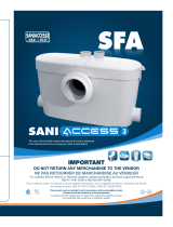
Rubber Feet
Floor Mounting Brackets
SFA
SANITOP
®
SANITOP
®
8
SANITOP
®
Type : ST
SFA SANIFLO
120 V - 60 Hz - 5.0A - 3/10 HP - IP44 -
7
2
1
7a
7a
C
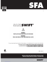
PERFORMANCE
VERTICAL DISTANCE
(DISTANCE VERTICALE)
feet / pieds
12
9
6
3
0
40 50 60 70 80 90
14 17 19 20
l/min
US gallon/min
FLOW RATE (DEBIT)
65
PAGE 2
B
E
B
7c
I
7b

SFA
SANITOP
®
SANITOP
®
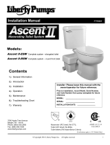
SCHEMATIC DIAGRAM SANITOP / SCHÉMA DU SANITOP
1 Boîtier
2a Couvercle
2b Joint du couvercle
3 Moteur
4 Panier
5 Couteau
7 Mini durite
8 Long coude
10 Turbine
11 Fond de pompe
12 Pieds du fond de pompe
14 Chambre de pressostat
15 Membrane
17 Micro-interrupteur
18 Isolant du câble
20a Joint de fond de pompe
20b Collier de maintien
25 Coude d’évacuation
26 Manchon trois sorties
28a Collier coude
d’évacuation 25/40
28b Collier coude-clapet
d’évacuation 32/55
31a Coude 46/46
34 Tie-wrap
35 Manchette WC
36 Collier 90-110
37 Bouchon 1-1/2"
38 Condensateur 45 uF
39 Collier en forme
de fer à cheval
40 Tige poussoir
41 Base de la chambre
de pressostat
48 Serre-câble 33.1
50 Agrafe
56 Pieds du boîtier
58
Capuchon
61 Amortisseur latéral panier
62 Amortisseur supérieur
panier
63 Amortisseur moteur
64 Patte de fixation
Composants de l’appareil
1 Case
2a Lid
2b Lid seal
3 Motor
4 Long grille
5 Blade
7 Short discharge pipe
8 Long elbow
10 Impeller PLUS / TOP
11 Pump cover plate
12 Pump cover feet
14 Pressure chamber
15 Membrane
17 Micro switch
18 Cable insulator
20a Ring for pump cover plate
20b Elbow clip
25 Discharge elbow
26 Three outlet pipe
28a Discharge hose clip 25/40
28b Discharge valve hose clip
32/55
31a 46/46 Rubber elbow
connector
34 Tie-wrap
35 Pan gasket
36 Screw clamp 90-110
37 1-1/2" Blankingplug
38 Condenser 45µf
39 Horseshoe clip
40 Push rod
41 Pressure chamber base
48 Cable grip 33.1
50 Spring clip assembly
56 Case feet
58 Plastic cap
61 Lateral grille absorber
62 Upper grille absorber
63 Lateral motor absorber
64 Fixation leg
Parts Description
PAGE 3

1
INTRODUCTION
This macerator is manufactured in a factory which is quality
certified to ISO 9001 (2000) accredited by AFAQ.This
equipment benefits from the latest technological innovations
concerning soundproofing.To benefit fully from the advantages
provided by this new generation of appliances, it is important
to comply with the installation instructions.
1.1 - GENERAL DESCRIPTION
The macerating unit is a residential pumping system for a
toilet and a sink. The system is comprised of three major
components :
- the macerating unit, which connects to the outlet of
a rear spigot outlet toilet
- The toilet bowl
- The toilet tank
The macerating unit also consists of three major parts: the
container which houses the operating mechanism; a pressure
chamber which automatically activates and deactivates; the
induction motor which drives the cutting blade and the impeller.
The macerating unit can simultaneously receive wastewater
from a sink and a toilet (only one water closet per unit).
Macerating units are designed for the disposal of human
waste, toilet paper and water. They are not intended to be
used for the disposal of kitchen waste, neither are they
intended to be used for the disposal of waste water from such
pump appliances as dishwashers and clothes washers.
Macerating system must discharge into a minimum 3/4-inch
sanitary drainage pipe. The macerating system will pump up
to 12 feet vertically, with a
1
/4" per foot gravity fall (minimum)
constantly throughout the horizontal run to the point of dis-
charge. If you require a vertical lift it should precede any “hori-
zontal” run and should commence as near as possible to the
discharge elbow. Once you have started the horizontal run,
you cannot change directions in a upward vertical manner.
ADDITIONAL INLETS
The macerating unit is equipped with two additional 1-
1
/2"
inlets at the top of the case. These inlets are to accommodate
a required vent connection (Refer to section 2.9) and a
connection to a sink.
SINK
Any type of sink can be connected to this macerating
system. As any bathroom fixture, a p-trap needs to be
installed under the sink. There should be a minimum
1
/4" per foot gravity fall towards the top inlet of the case.
Note: In case the sink connection inlet is not used, you will
need to block off this inlet with the plug provided. Only this
inlet can be blocked as the vent connection should always
be vented.
1.2 - NORMAL OPERATING CYCLE
As the flush is operated or as the lavatory discharged, the water
and waste enter the unit and the water level begins to rise,
triggering the micro-switch in the pressure chamber. This in
turn activates the motor. The shredded waste is picked up by
the impeller and discharged through a
3
/4" or 1" outlet pipe to
a sanitary sewer or soil stack.
Safety note: For safety the macerating unit should never be
activated with the lid removed.
2
INSTALLATION
2.1 - PREPARING THE MACERATING UNIT
The plastic discharge elbow/check valve assembly should be
inserted (long end) into the rubber hose located on the top of
the lid. The step-down rubber fitting should then be inserted at
the discharge side of the elbow assembly and secured with the
provided metal clamps. The step-down rubber fitting may need
to be cut depending on the discharge pipe diameter. Three
metal clamps should be used to secure all fittings.
2.2 - CONNECTION TO A SINK
• To connect to a sink, use the elbow connector provided with
the system. Connect this fitting to the top inlet of the case
and secure with clamps.
• If the inlet for the sink is not used, plug the unused inlet with
a blanking plug (provided) after greasing the joint.
2.3 - WATER CLOSET ASSEMBLY
The tank comes with the fill and flush valve assembled,
however, please ensure that all screws, nuts, etc. are tightened
2.4 - SYSTEM ASSEMBLY
Sanitop : See page 2 drawing 7a
1. Place the macerating unit in the desired spot and connect
all inlet and outlet waste piping to the unit. (See Connection
to discharge pipe work).
2. Place the spigot outlet of the toilet bowl firmly against the
white accordion connector and mark the floor through the
holes in the bowl.
3. Remove bowl and bore two holes approximately 2
1/4" deep
with a
5/16" masonry drill bit. Insert plastic plugs into holes.
If the floor is wood, bore a pilot hole with a
1/4" drill bit.
4. Place the bowl in front of the macerating unit and pull the
accordion gasket all the way onto the rear spigot outlet. Attach
with supplied gear clamp. Check that gasket and clamp are
even all around.
5. Move the bowl over the holes in floor. Slip the plastic china
protectors over the lag screws.Tighten lag screws (do not over
tighten) and snap plastic cover caps in place.
6. Locate the tank to bowl kit and place foam gasket on the
spud of the flush valve and over nut. Place tank on top of the
bowl. Insert screws and gasket through the tank and tighten nuts
underneath. Do not overtighten as this may damage the china.
The system is supplied with fixing lugs to prevent it from
moving during use. To optimize the latest technical
developments concerning soundproofing incorporated into this
unit,it is important to:
• position the WC pan so that it is not in contact with a partition
or wall of the room.
• place the WC pan on a perfectly level surface to ensure that
the resilient mounts are fully efficient.
• fix the discharge pipe correctly with distances of not more
than 3ft (1m) between the fastenings.
2.5 - CONNECTION TO WATER SUPPLY
Connect the water supply hose to the fill valve.
2.6 - CONNECTION TO THE DISCHARGE PIPE WORK
These macerating units have an elbow, and a «step-down»
bushing (simply cut off the appropriate portion of the bushing
in order to fit it to the discharge pipe). Use ridged wall pipe, not
flexible pipe or hose, as flexible pipe may distort over time. Use
3/4" or 1" discharge pipe.
Install a “full-port” ball or gate valve and a union in the
discharge pipe in order to facilitate the removal of the
macerating unit. Place the union or hose connector then the
valve at the lower portion of the discharge pipe.
If you wish the unit to pump vertically and horizontally you may
calculate that 3 feet of vertical lift is equivalent to 30 feet of
“horizontal” run.

Each bend or change of direction causes minor losses, which
must be deducted from the discharge performance figures in
accordance with the usual head loss practice. (Rough guide:
reduce discharge height by 3 feet for each 90° turn).
The discharge pipe work can be made from
3/4" diameter
material. Copper (Type M), CPVC or PVC. Use long turn bends
and not elbows, elbows are not normally available in plastic
piping, use two 45° pieces back to back to make a 90° elbow.
The connection to the soil-stack or sewer pipe should be
made with an approved wye fitting.When in doubt about this
procedure please have a plumbing contractor install this for you.
2.7 - SEWER PIPE (COPPER, CAST IRON, PVC, ABS)
1.Install an appropriate wye fitting into the sewer pipe, (with
1
1/2" branch hub).
2. Read point 3a first if using a copper wye. Glue a bushing,
((spigot x FPT) 1 1/2" x 3/4") into the 1 1/2" hub of the Y fitting.
3. Screw male adapter, ((MPT x Hub)
3/4" x 3/4" sweat) into
the bushing, when discharge piping is in copper buy brass
adapter, when in CPVC buy CPVC adapter.
a. When in copper; solder a length of pipe to the male adapter
first, allow to cool then screw assembly into female bushing
into the branch socket. When soldering pipe systems together,
wind a wet rag around the plastic to keep it cool. Maintain at
least a distance of 6” between the plastic and the piece
soldered. Use Teflon tape or 100% Teflon dope on male
thread. Any other dope product will deteriorate plastic material.
b. When using CPVC material, use glue to glue the CPVC
pipe into the ABS fitting. Caution: Do not use ABS glue on
CPVC materials, as the plastic will not bond.
2.8 - CONNECTION TO ELECTRICAL SUPPLY
All wiring should be in accordance with the applicable
electrical code in your territory. The macerating system requi-
res a single-phase 120-volt, 15 Amp. supply. When
installed in a bathroom, the receptacle should be 40 inches
away (in a straight line) from a shower or bathtub. Connect
only to receptacle protected by a ground fault circuit
interrupter (GFCI).
Warning: risk of electric shock - this pump is suplied with a
grounding conductor and grounding type attachment plug to
reduce the risk of electrical shock. Be certain that it is
connected only to a properly grounded - type receptacle.
2.9 - CONNECTION TO A VENT SYSTEM
Sanitop : See page 2 drawing 7c
The macerating unit must be vented. It has 2 inlets on the top
of the cover: a 1
1/2" cap and a hole of smaller diameter.
The unit must be connected to a vent system according to
plumbing codes. Insert the elbow connector (provided) on
the 1-1/2” port and clamp it down. Then, connect to the vent
pipe. Note that all fixtures connected to the system must also
be vented.
Warning: Do not use an air admittance valve or a
mechanical spring-loaded venting device, as these
devices are one-way valves. The air pressure in and
outside the macerating unit must be equal, a “cheater”
vent will obstruct the airflow one direction.
Note: The smaller diameter
1/2" hole must be plugged with a
plastic cap supplied (i).
2.10 - ACTIVATING THE UNIT
1. Ensure that the toilet is free of building debris prior to
activating.
2. Open the shut-off valve and let the tank fill up.
3. Ensure power supply is on.
4. Flush several times with intervals in between depositing a
few sheets of toilet paper into the bowl to check discharge
piping. Usually, there should be no paper remaining in the
bowl after each flush.
3
USAGE
The normal domain of application of SFA macerating units only
concerns the disposal of human waste, toilet paper and water.
SANITOP is designed for family use only and cannot accept
without damage the disposal of sanitary items such as
condoms, tampons, sanitary pads and cotton swabs.
CAUTIONARY NOTES:
Do not discharge any acids, alkaloids, solvents painting,
paint strippers, food waste, plastic bags, metal such as
nails, hairpins, wood, building materials, kitty litter or
anything that could halt or damage or corrode the unit.
Disregarding the above might damage the macerating unit
and shall void your warranty.
Do not hang bleach blocks or hydrochloride cleaners in the
toilet tank. These solutions have been shown to
deteriorate the plastic and neoprene components of the
flush and fill valves, and may cause leaks. In the event of a
power loss do not use the toilet or any other sanitary
fixture connected to the macerating unit since it will not
work until the power is restored.
The toilet works as a conventional flushing toilet and needs no
maintenance in normal use. However, there is nothing wrong
with cleaning out the macerating unit once a year. Do not use
bleach (Be careful not to let water enter the electrical cord
opening).
The macerating unit starts automatically once the toilet is
flushed or if the sink is discharged and ceases operation once
the contents have been pumped away.
Whenever the unit is not to be used for long periods of time
(vacation, power failure, maintenance, etc.) turn off the water
supply to the tank and flush the unit to evacuate the water. No
leakage into the bowl should ever be permitted from the tank.
In areas, which are prone to freezing, the total system must
be properly winterized.This includes the draining of all pipes,
the toilet tank and bowl and the macerating tank. The
macerating system is simple to winterize. Pour a jug of plum-
bers’anti-freeze into the tank and flush the toilet. This will
cause the macerating unit to activate and all remaining water
will be replaced by plumber’s anti-freeze. No parts or labour
are warranted when a breakdown occurs due to freezing.
Ensure that there are no faucets left open. Drops will
eventually fill up the pump and the resultant repeated
start-stop of the motor may heat up to such an extent, that
the thermal overload switch may eventually operate and
automatically stop the motor, thus possibly causing a flood.
This device is not designed for persons (including children)
with limited physical, sensory or mental abilities, or those
with minimal experience and knowledge, unless they are
monitored and are given the necessary instructions for
using the device, with the help of a person responsible for
their safety. Monitor children and make sure they do not
play with the device.
4
PROBLEM SOLVING
4.1 - CHECKUP
The macerating unit is very reliable. With normal use long
service is assured. However, in certain cases an incident may
occur which you may rectify yourself. Before taking any action
check the following points:
1. Plumbing system. Flush system, water supply turned on.
2. Electrical system. G.F.C.I. breaker on. Receptacle on. Fuse
okay. Breaker on. Male plug still in receptacle. Check that
the thermal overload has not operated; (wait approximately
20 minutes for unit to reactivate).
3. Hydraulic System. Check that the discharge and vent pipe
are not blocked.

If the macerating unit turns on intermittently without the flush
having been activated or water having been discharged,
check that water out of the toilet tank is not leaking into the
bowl. Or, that there is no leakage back into the macerating
unit due to incorrect seating of the check valve and/or that the
discharge elbow is seated properly.
4.2 - DISASSEMBLY FOR LITTLE INTERVENTION
As the unit is connected to the water and electrical supply,
it is important to check that the following actions have been
taken before removing the unit:
1. If possible, close off the water supply to the tank and close
the ball or gate valve on the outlet pipe.
2. Pull the electrical cord out of the receptacle before
removing unit.
3. Empty out as much water as possible from the toilet tank
and the toilet bowl.
4. Disconnect toilet from unit. Remove toilet bowl and set
aside against a wall to prevent from tipping over.
5. The use of a dry/wet type vacuum cleaner might assist you
greatly in removing the residual water in the bowl or
macerating unit.
6. When you have to remove the macerating unit, carefully
disconnect the inlet drainpipes, (there might be residual
water inside).
7. For Sanitop, use the WC inlet to remove a foreign object
with the help of a folded wire.
4.3 - RETURN AND REPAIR OF THE MACERATING UNIT
In the event that the unit needs to be returned for service,
please call for possible options, or to inquire about an
authorized repair shop in your area. When you are required to
return the macerating unit to the manufacturer, please ensure
that prior to shipping, the unit has been cleaned and
disinfected inside and outside. A labour charge will be in
effect for cleaning ($50.00). Before returning any unit, a return
authorization is needed from the manufacturer. Units returned
without prior RGA number will be refused and returned collect.
If you return the macerating unit in its original packaging,
please remove the discharge elbow and retain until
re-assembly. If elbow is not removed, damage due to
shipping might occur.
Please package the macerating unit properly with adequate
shock absorbent material around it.
Send this package prepaid to the manufacturer, making sure
to insure against loss and/or transit damage, (the amount of
$300.00 will suffice).
If any repairs are done outside the warranty period, or when
the user has damaged the macerating unit, you will be
apprised of repair costs. All repair work will be conducted on
a pre-paid basis only.
5
MAINTENANCE (for qualified personnel only)
5.1 - See paragraph 4 PROBLEM SOLVING (4.1 and 4.2)
5.2 - If you need to open the macerating unit, first release the
discharge elbow, unclip the lid and pull up lid. In some cases
the lid might be stuck to the case very tightly, (during
assembly soapy water is used which dries up in time).
If required to remove motor from the case, unscrew motor retai-
ning screws (if any). Also release the insulator cable to the lid.
Lift out motor assembly. Do not attempt to dismantle the motor
assembly itself as it is “clipped” together. These clips may
break off when trying to unclip them. In addition to damaging
the clips the motor seals may be damaged when the lid is
removed from the motor housing. The motor is filled with
dielectric oil, do not remove it or replace with regular oil.
Please note, the distributor purposely does not keep seals,
bearings, or oil in stock.
5.3 - SANITOP FUNCTION CHECKUP IMPELLER
Invert motor to gain access to pump chamber at the base.
Unclip pump cover plate from motor housing.
Unscrew the pump impeller counter clockwise, releasing it
from the spindle (block the spindle to unscrew). Clean pump
chamber and discharge elbow and pipe work to ensure no
blockage exists. Check that drive shaft rotates freely. Also
check that the air relief-hole in the wall of the chamber is
clear.
CUTTER BLADE
The blades can be easily removed if they ever require
replacement. Simply remove the retaining circlip on top of
the blade/rotor assembly and lift rotor/blade assembly off the
spindle. The blades can now be slid sideways, removed and
replaced.
Safety note: The blades are sharp and should be handled
with extreme care.
5.4 - CAUTIONARY NOTE
Do not immerse unit totally in water. Do not let water enter the
electrical cord entrance opening.
5.5 - REASSEMBLY OF THE LID
When replacing the lid grease the rubber gasket lightly with
soapy water or dishwasher liquid. (Do not use Vaseline as this
may expand the neoprene materials).The gasket must be
inside the lid first. Start by pushing the lid down at the cord
side first, then work your way around and tap on the lid with a
rubber mallet or bloc

6
ADVICE
PIPE SUPPORTS
All sanitary pipe work must be
supported, in accordance with the pipe
manufacturer’s recommendations.
Avoid dipping or trapping, which may
cause the build up of residual “solids”
and sub- sequent blockage.
BENDS
Where possible long sweeping bends
should be used. Do not use short
elbows. If sweeping 90° elbows are not
available use two 45° elbows to make
a 90° turn.
VERTICAL INSTALLATION FIRST
If vertical lift is required, this must
precede the horizontal pipe run.
DIRECTLY VERTICAL
All vertical lifts should rise as directly
above the unit as possible, allowing
only for the need to clear the toilet
tank. Any initial horizontal pipe run
from the unit, prior to a vertical lift
should not exceed 12-18 inches.
EASY ACCESS
The unit should be accessible and
removable in the event of maintenance
being required. During the installation
a full-port ball valve should be installed
at the base of any vertical discharge
pipe work from the unit to allow easy
service of the unit.
NO DIRECT FALL
Where the point of discharge into the
soil stack is significantly lower than the
base of the unit, a vacuum relief valve
may need to be fitted at the highest
point in the pipe run in order to avoid
siphonage of the water seal.
THREE FEET MINIMUM
The macerating unit must be installed
at least 3 feet from the soil stack. This
will allow the macerator to operate for
an adequate period of time to ensure
efficient waste reduction.
SOIL STACK CONNECTION
All discharge pipe work must be
connected to the soil stack by an
appropriate and approved connection.
A “tee” or ”y” fitting as shown is
preferable.
NO DIAGONAL “UPHILL” PIPE
RUNS
All discharge pipe work from the
unit should run either directly vertical
upwards from it or in a horizontal plane
(with a small gravity flow) to the point of
discharge. Pipe work should not be
installed with diagonal upward slope
from the unit to the point of discharge.
PIPE WORK
All pipe work should be either copper,
PVC or CPVC (Do not use flexible
pipes). Hangers should not be less
than three feet apart to prevent pipe
rattling.
DISCHARGE
Never discharge directly into an open
drain, fixture, manhole or rainwater
drainpipe. It is illegal for it constitutes a
health hazard. Direct connections into
sanitary waste systems only, shall be
acceptable.
FREEZING
Ensure all pipe work susceptible to
freezing is adequately insulated or
heated. In unheated buildings, the
toilet, piping and macerating unit must
be properly winterized with “RV or
plumbers” anti-freeze or drained
completely.
ELECTRICITY
Before attempting any maintenance or
servicing, the unit must be disconnec-
ted from the power source. The mace-
rating system must be connected to a
Ground Fault Circuit Interrupter (GFCI).

When claiming a warranty repair we will need the information you have written down below. Please ensure that you have all
particulars available when requesting warranty work.
Name Owner: ___________________________________________________________________________________________________________
Installation Address: _____________________________________________________________________________________________________
Purchased From: ________________________________________________________________________________________________________
Installed By: ____________________________________________________________________________________________________________
Date of Purchase: _______________________________________________________________________________________________________
________________________________________________________________________________________________________________________
Serial Number: __________________________________________________________________________________________________________
Date of Manufacture: _______________________________________________________________________ (see manufacturers’ tag on unit)
7
TROUBLE SHOOTING GUIDE
PROBLEM
Motor turns normally but the water
evacuates slowly from the bowl,
(flush incomplete).
Waste build up in bowl.
The macerating unit does not start
up. Water does not evacuate.
The motor hums but does not turn
the water does not evacuate.
Water goes down slowly and motor
works intermittently.
The water evacuates from the toilet
but the motor runs for a very long
time, thermal overload activates.
After evacuation the motor engages
several times in succession before it
stops completely.
Motor turns noisily without stopping
or pumping.
After evacuation the motor starts,
stops, and re-engages indefinitely.
For Sanitop, the motor turns with a
rattling noise.
Water backs up into shower tray or
bathtub.
CAUSE
Discharge pipe blocked or valve not
vented properly.
Inadequate water supply from
reservoir.
Power supply off. Thermal overload
cut out.
Foreign body blocking the macera-
ting blades. Defective capacitor.
Clogged up (sanitary napkin, news-
paper, plugged breather hole etc.).
Kinked/blocked discharge pipe,
damaged membrane, defective
impeller, and partially blocked pump.
Water siphons back into the
macerating unit. Check valve
is not functioning properly.
Siphonage or insufficient back
pressure in discharge pipe, causing
airlock. Foreign object.
Water leaking from reservoir into
bowl. Faulty non-return check valve.
Solid item has fallen into the grille of
the macerating unit.
Inadequate gravity-fall into macera-
ting unit or blockage in drain piping.
Faulty inlet control flap.
REMEDY
Clean out the piping and air breather
hole.
Check and/or adjust water level in
reservoir.
Wait for thermal overload to engage
(approx. 20 min).
See “dismantling”.
Flush 3 or 4 times to clear. Cleaning
or dismantling may be required.
Clean out the breather hole.
Check installation.
Flush once or twice with clean water
to clear valve or remove valve to
clean.
Modify discharge pipe run to
eliminate siphonage and/or increase
backpressure. E.g. reduce pipe size,
put extra bend in run. Remove
foreign object.
Check flush valve. Check and clean
non-return check valve.
Clear object from grille area.
1
/4” per foot gravity fall minimum
into macerating unit from other sani-
tary fixtures.
Clean out the flap.
IMPORTANT

LIMITED WARRANTY
2 Year Warranty from Date of Purchase
Subject to the terms and conditions set out below, SFA-SANIFLO INC., (hereafter designated the as the
Company) warrants that it will repair or replace the product or any of its component parts, at the
Company’s discretion if it deems that the product or part it is defective or does not meet the rated
performance due to a maufacturing or material default.
If replacement is to be issued, this will only be extended to the first 180 days starting from the date of
purchase. Warranty repairs will apply after such date up to the warranty’s date of conclusion.
TERMS AND CONDITIONS
The conditions of this warranty are the following:
• The product must be installed in accordance with the use described in the enclosed manuals.
• The product must be connected to a single phase 120V, 60Hz electrical outlet and was not subject
to any negligence, accident or exposure to harmful products or substances..
• The alleged defect or fault must be reported either to the installer or to the Company during the
warranty coverage period.
• The warranty coverage period is valid for 2 years.
PART OR PRODUCT EXCHANGE
The product may be exchange without cost only at the sales outlet where it was purchased subject to
the following conditions:
•The customer must have an “authorized return number” from the manufacturer in order to validate
exchange.
•The customer must produce proof of purchase to validate exchange.
LIMITATIONS
1.Fill and flush mechanism are guaranteed as per OEM warranty only.
2.Vitreous china are guaranteed only for a factory defect.
3. Cost of disconnection and reconnection (ie labor charges) are not covered by the warranty and are
end-users responsability.
4. Cost of mail or freight when a part or parts of the system have to be repaired at the company are
not covered by this warranty.
5. In no event shall the company be reliable for any special, incidental or consequential damage, loss, or
injury of whatsoever nature or kind arising from or in connection with the product or any component
thereof.
6. The guarantee is transferable only when the product remains at the same premises as where it was
installed initialy.
Except as set forth in this Limited Warranty, the company disclaims all other warranties, express or
implied, with respect to the product or any component thereof including, but not limited to, all implied
warranties for merchantability and fitness for a particular purpose.
For Service and other inquiries, please call either of the addresses listed below.
United States Canada
SFA-SANIFLO INC.
SFA-SANIFLO INC.
105 Newfield Avenue, Suite A 1-685 Speedvale Avenue West
Edison, NJ 08837 Guelph ON
N1K 1E6
Customer toll free: 800-571-8191 Customer toll free: 800-363-5874 English
Customer toll free: 800-877-8538 French
Telephone: 732-225-6070 Telephone: 519-824-1134
Telefax: 732-225-6072 Telefax: 519-824-1143
Web Site: www.saniflo.com Web Site: www.saniflo.ca
/