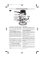
Operating/Safety Instructions
Consignes de fonctionnement/sécurité
Instrucciones de funcionamiento
y seguridad
1617
1617EVS
1617PK
1617EVSPK
1618
1618EVS
0 601 617 061
IMPORTANT: IMPORTANT : IMPORTANTE:
Read Before Using Lire avant usage Leer antes de usar
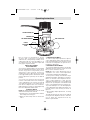
Consumer Information
Renseignement des consommateurs
Información para el consumidor
Toll Free Number: Appel gratuit : Número de teléfono gratuito:
1-877-BOSCH99 (1-877-267-2499) http://www.boschtools.com
For English Parlez-vous français? ¿Habla español?
See page 2 Voir page 23 Ver página 44
2
1
0
IN
50
40
30
20
10
0
MM
BM 2610908996 5/03 5/20/03 9:06 AM Page 1

Read and understand all instructions. Failure to follow all instructions listed
below, may result in electric shock, fire and/or serious personal injury.
SAVE THESE INSTRUCTIONS
-2-
Work Area
Keep your work area clean and well lit.
Cluttered benches and dark areas invite
accidents.
Do not operate power tools in explosive
atmospheres, such as in the presence of
flammable liquids, gases, or dust. Power
tools create sparks which may ignite the dust
or fumes.
Keep by-standers, children, and visitors
away while operating a power tool.
Distractions can cause you to lose control.
Electrical Safety
Double Insulated tools are equipped with a
polarized plug (one blade is wider than the
other.) This plug will fit in a polarized outlet
only one way. If the plug does not fit fully in
the outlet, reverse the plug. If it still does not
fit, contact a qualified electrician to install a
polarized outlet. Do not change the plug in
any way. Double Insulation xxxx eliminates the
need for the three wire grounded power cord
and grounded power supply system. Before
plugging in the tool, be certain the outlet
voltage supplied is within the voltage marked
on the nameplate. Do not use “AC only” rated
tools with a DC power supply.
Avoid body contact with grounded surfaces
such as pipes, radiators, ranges and
refrigerators. There is an increased risk of
electric shock if your body is grounded. If
operating the power tool in damp locations is
unavoidable, a Ground Fault Circuit Interrupter
must be used to supply the power to your tool.
Electrician’s rubber gloves and footwear will
further enhance your personal safety.
Don't expose power tools to rain or wet
conditions. Water entering a power tool will
increase the risk of electric shock.
Do not abuse the cord. Never use the cord
to carry the tools or pull the plug from an
outlet. Keep cord away from heat, oil, sharp
edges or moving parts. Replace damaged
cords immediately. Damaged cords increase
the risk of electric shock.
When operating a power tool outside, use an
outdoor extension cord marked "W-A" or
"W." These cords are rated for outdoor use and
reduce the risk of electric shock. Refer to
“Recommended sizes of Extension Cords” in
the Accessory section of this manual.
Personal Safety
Stay alert, watch what you are doing and
use common sense when operating a power
tool. Do not use tool while tired or under the
influence of drugs, alcohol, or medication. A
moment of inattention while operating power
tools may result in serious personal injury.
Dress properly. Do not wear loose clothing
or jewelry. Contain long hair. Keep your hair,
clothing, and gloves away from moving
parts. Loose clothes, jewelry, or long hair can
be caught in moving parts. Keep handles dry,
clean and free from oil and grease.
Avoid accidental starting. Be sure switch is
“OFF” before plugging in. Carrying tools with
your finger on the switch or plugging in tools
that have the switch “ON” invites accidents.
Remove adjusting keys or wrenches before
turning the tool “ON”. A wrench or a key that
is left attached to a rotating part of the tool may
result in personal injury.
Do not overreach. Keep proper footing and
balance at all times. Proper footing and
balance enables better control of the tool in
unexpected situations.
Use safety equipment. Always wear eye
protection. Dust mask, non-skid safety shoes,
hard hat, or hearing protection must be used
for appropriate conditions.
Tool Use and Care
Use clamps or other practical way to secure
and support the workpiece to a stable
platform. Holding the work by hand or against
your body is unstable and may lead to loss of
control.
Do not force tool. Use the correct tool for
your application. The correct tool will do the
job better and safer at the rate for which it is
designed.
Do not use tool if switch does not turn it
“ON” or “OFF”. Any tool that cannot be
controlled with the switch is dangerous and
must be repaired.
!
WARNING
Power Tool Safety Rules
BM 2610908996 5/03 5/20/03 9:06 AM Page 2

-3-
Safety Rules for Routers
Disconnect the plug from the power source
before making any adjustments, changing
accessories, or storing the tool. Such
preventive safety measures reduce the risk of
starting the tool accidentally.
Store idle tools out of reach of children and
other untrained persons. Tools are dangerous
in the hands of untrained users.
Maintain tools with care. Keep cutting tools
sharp and clean. Properly maintained tools,
with sharp cutting edges are less likely to bind
and are easier to control. Any alteration or
modification is a misuse and may result in a
dangerous condition.
Check for misalignment or binding of
moving parts, breakage of parts, and any
other condition that may affect the tools
operation. If damaged, have the tool
serviced before using. Many accidents are
caused by poorly maintained tools. Develop a
periodic maintenance schedule for your tool.
Use only accessories that are recommended
by the manufacturer for your model.
Accessories that may be suitable for one tool,
may become hazardous when used on another
tool.
Service
Tool service must be performed only by
qualified repair personnel. Service or
maintenance performed by unqualified
personnel could result in a risk of injury. For
example: internal wires may be misplaced or
pinched, safety guard return springs may be
improperly mounted.
When servicing a tool, use only identical
replacement parts. Follow instructions in the
Maintenance section of this manual. Use of
unauthorized parts or failure to follow
Maintenance Instructions may create a risk of
electric shock or injury. Certain cleaning agents
such as gasoline, carbon tetrachloride,
ammonia, etc. may damage plastic parts.
Hold tool by insulated gripping surfaces
when performing an operation where the
cutting tool may contact hidden wiring or its
own cord. Contact with a "live" wire will make
exposed metal parts of the tool "live" and
shock the operator. If cutting into existing walls
or other blind areas where electrical wiring may
exist is unavoidable, disconnect all fuses or
circuit breakers feeding this worksite.
Always make sure the work surface is free
from nails and other foreign objects. Cutting
into a nail can cause the bit and the tool to
jump and damage the bit.
Never hold the workpiece in one hand and
the tool in the other hand when in use.
Never place hands near or below cutting
surface. Clamping the material and guiding the
tool with both hands is safer.
Never lay workpiece on top of hard
surfaces, like concrete, stone, etc...
Protruding cutting bit may cause tool to jump.
Always wear safety goggles and dust mask.
Use only in well ventilated area. Using
personal safety devices and working in safe
environment reduces risk of injury.
After changing the bits or making any
adjustments, make sure the collet nut and
any other adjustment devices are securely
tightened. Loose adjustment device can
unexpectedly shift, causing loss of control,
loose rotating components will be violently
thrown.
Never start the tool when the bit is engaged
in the material. The bit cutting edge may grab
the material causing loss of control of the
cutter.
Always hold the tool with two hands during
start-up. The reaction torque of the motor can
cause the tool to twist.
The direction of feeding the bit into the
material is very important and it relates to
the direction of bit rotation. When viewing
the tool from the top, the bit rotates
clockwise. Feed direction of cutting must be
counter-clockwise. NOTE: inside and outside
cuts will require different feed direction, refer to
section on feeding the router. Feeding the tool
in the wrong direction, causes the cutting edge
of the bit to climb out of the work and pull the
tool in the direction of this feed.
BM 2610908996 5/03 5/20/03 9:06 AM Page 3

Never use dull or damaged bits. Sharp bits
must be handled with care. Damaged bits can
snap during use. Dull bits require more force to
push the tool, possibly causing the bit to break.
Never touch the bit during or immediately
after the use. After use the bit is too hot to be
touched by bare hands.
Never lay the tool down until the motor has
come to a complete standstill. The spinning
bit can grab the surface and pull the tool out of
your control.
Never use bits that have a cutting diameter
greater than the opening in the base.
Some dust created by power
sanding, sawing, grinding,
drilling, and other construction activities
contains chemicals known to cause cancer,
birth defects or other reproductive harm.
Some examples of these chemicals are:
• Lead from lead-based paints,
• Crystalline silica from bricks and cement and
other masonry products, and
• Arsenic and chromium from chemically-
treated lumber.
Your risk from these exposures varies,
depending on how often you do this type of
work. To reduce your exposure to these
chemicals: work in a well ventilated area, and
work with approved safety equipment, such as
those dust masks that are specially designed to
filter out microscopic particles.
-4-
!
WARNING
BM 2610908996 5/03 5/20/03 9:06 AM Page 4
-5-
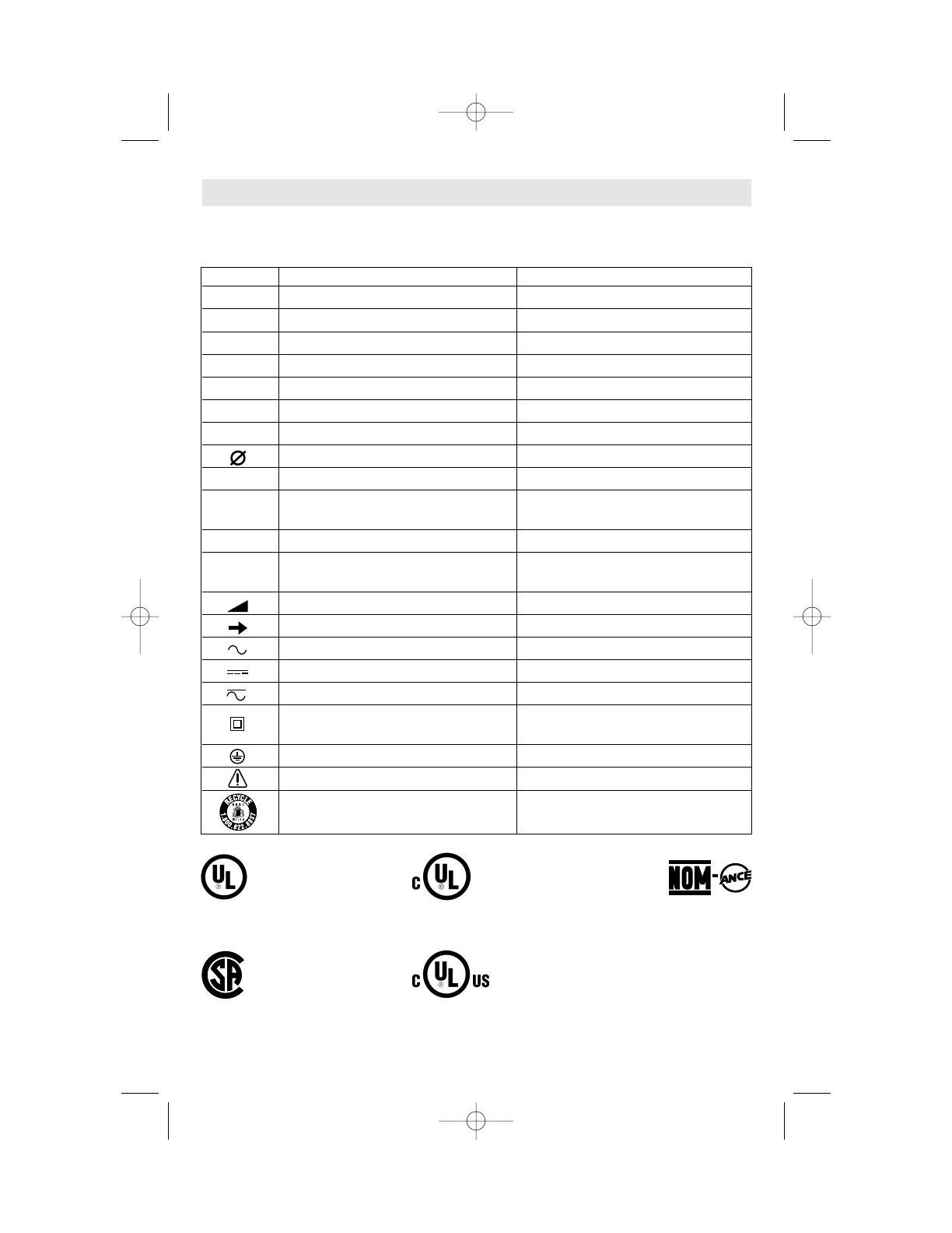
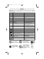
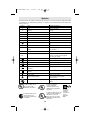
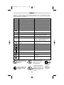
IMPORTANT: Some of the following symbols may be used on your tool. Please study them
and learn their meaning. Proper interpretation of these symbols will allow you to operate the
tool better and safer.
Symbol Name Designation/Explanation
V Volts Voltage (potential)
A Amperes Current
Hz Hertz Frequency (cycles per second)
W Watt Power
kg Kilograms Weight
min Minutes Time
s Seconds Time
Diameter Size of drill bits, grinding wheels, etc.
n
0
No load speed Rotational speed, at no load
.../min Revolutions or reciprocation per minute Revolutions, strokes, surface speed,
orbits etc. per minute
0 Off position Zero speed, zero torque...
1, 2, 3, ... Selector settings Speed, torque or position settings.
I, II, III, Higher number means greater speed
Infinitely variable selector with off Speed is increasing from 0 setting
Arrow Action in the direction of arrow
Alternating current Type or a characteristic of current
Direct current Type or a characteristic of current
Alternating or direct current Type or a characteristic of current
Class II construction Designates Double Insulated
Construction tools.
Earthing terminal Grounding terminal
Warning symbol Alerts user to warning messages
Ni-Cad RBRC seal Designates Ni-Cad battery recycling
program
Symbols
0
This symbol designates
that this tool is listed by
Underwriters Laboratories.
This symbol designates
that this tool is listed by
the Canadian Standards
Association.
This symbol designates
that this tool is listed to
Canadian Standards by
Underwriters Laboratories.
This symbol
designates
that
this tool
complies
to NOM
Mexican
Standards.
This symbol designates
that this tool is listed by
Underwriters Laboratories,
and listed to Canadian
Standards by Underwriters
Laboratories.
BM 2610908996 5/03 5/20/03 9:06 AM Page 5
-6-
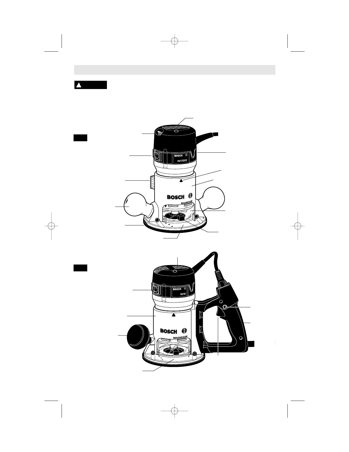
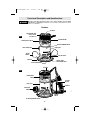
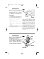
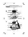
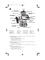
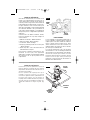
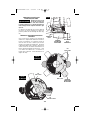
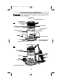
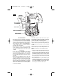
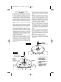
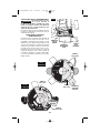
Functional Description and Specifications
Disconnect the plug from the power source before making any assembly,
adjustments or changing accessories. Such preventive safety measures reduce
the risk of starting the tool accidentally.
!
WARNING
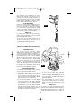
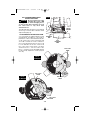
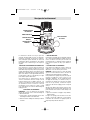
FIG. 1
SPEED CONTROL DIAL
Models 1617EVS
& 1618EVS only
SUB -BASE
TRIGGER
SWITCH
"LOCK-ON"
BUTTON
D-HANDLE
ROUND
HANDLE
BASE CLAMP LEVER
CHIP DEFLECTOR
MOTOR HOUSING
ROCKER ON\OFF SWITCH
POWER ON/OFF
SWITCH
TEMPLET GUIDE
QUICK CHANGE LEVER
MOTOR ALIGNMENT ARROW
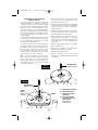
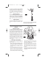
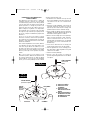
FIG. 2
AIR VENTS
AIR VENTS
REVERSIBLE
HANDLE
BIT ROTATION ARROW
BIT ROTATION ARROW
Routers
BASE TYPE S
BASE TYPE D
BM 2610908996 5/03 5/20/03 9:06 AM Page 6
-7-
2
1
0
IN
50
40
30
20
10
0
M
M
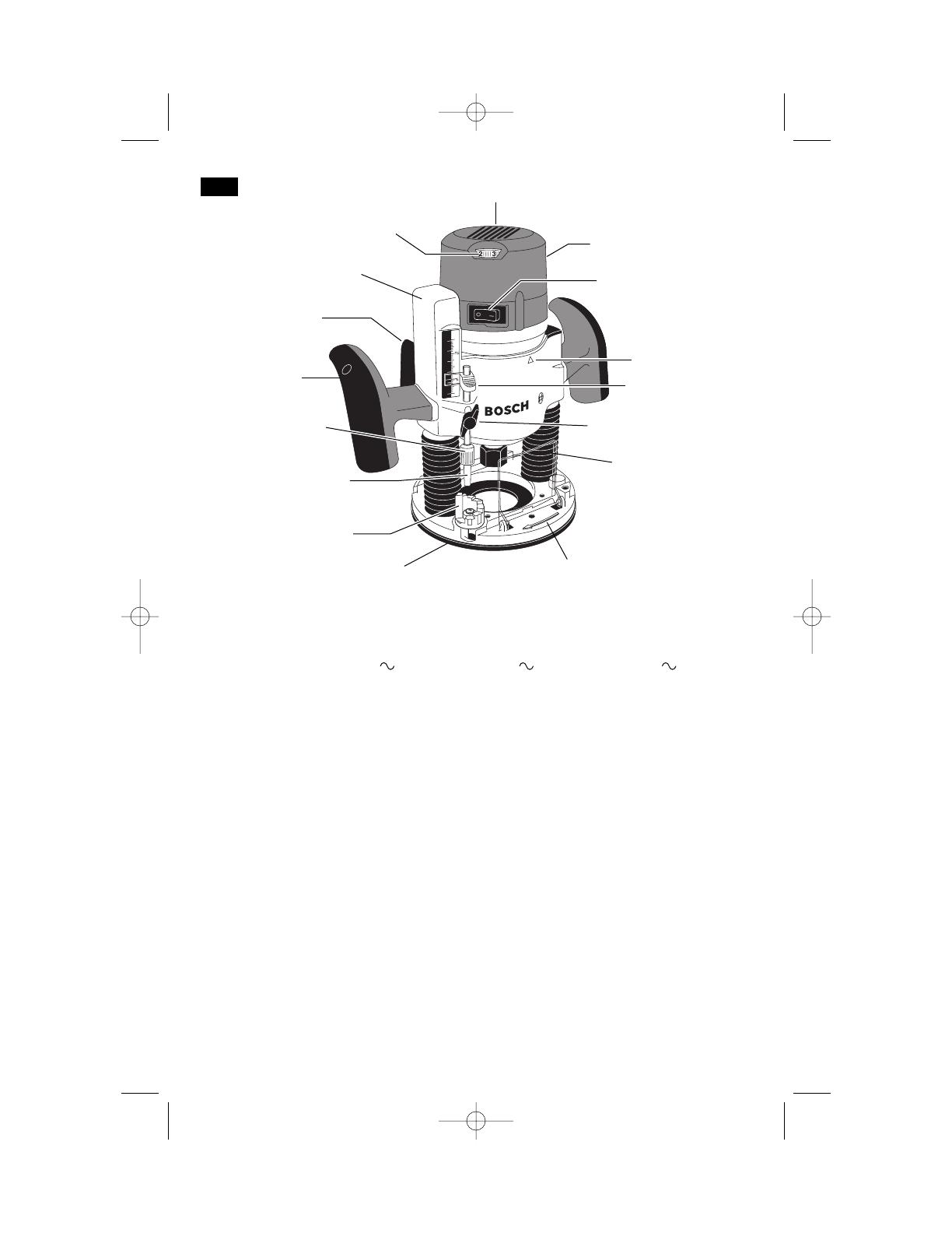
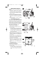
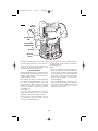
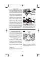
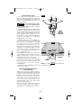
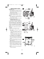
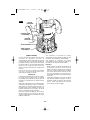
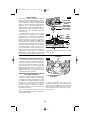
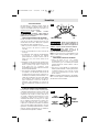
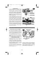
FIG. 3
SPEED CONTROL DIAL
Model 1617EVSP only
SUB-BASE
PLUNGE HANDLE
CHIP DEFLECTOR
MOTOR HOUSING
ROCKER ON\OFF SWITCH
MOTOR ALIGNMENT
ARROW
AIR VENTS
BIT ROTATION ARROW
BASE TYPE P
Model number 1617 & 1618 1617EVS & 1618EVS 0 601 617 061
Voltage rating 120V 50 - 60Hz 120V 50 - 60Hz 220V 50 - 60Hz
Amperage rating 11A 12A 6A
No load speed n
0
25,000/min n
0
8,000-25,000/min n
0
25,000/min
Collet capacities 1/4", 3/8", 1/2", 8mm 1/4”, 3/8”, 1/2”, 8mm 1/4”, 3/8”, 1/2”, 8mm
RA1160 fixed-base shop router base marked type "S" is designed for use with these router motors:
1617 router motor (16171)
1617EVS router motor (16176)
0 601 617 061 router motor (0 601 617 161)
1618 router motor (16181)
1618EVS router motor (16186)
RA1162 D-handle router base marked type "D" is designed only for use with these router motors:
1618 router motor (16181)
1618EVS router motor (16186)
RA1166 plunge router base marked type "P" is designed for use with these router motors:
1617 router motor (16171)
1617EVS router motor (16176)
0 601 617 061 router motor (0 601 617 161)
1618 router motor (16181)
1618EVS router motor (16186)
PLUNGE LOCK LEVER
DEPTH ROD
DEPTH ROD KNOB
DEPTH STOP TURRET
DEPTH INDICATOR
DEPTH ROD FINE
ADJUSMENT KNOB
BM 2610908996 5/03 5/20/03 9:06 AM Page 7
-8-
Assembly
A wide assortment of router bits with different
profiles is available separately. Use 1/2" shank
whenever possible, and only use good quality
bits.
To prevent personal injury,
always remove the plug
from power source before removing or
installing bits or accessories.
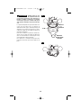
INSTALLING A ROUTER BIT
Place router upside down or lay router on its
side with the base resting on the bench.
Another option is to remove the motor from the
base before installing the bit.
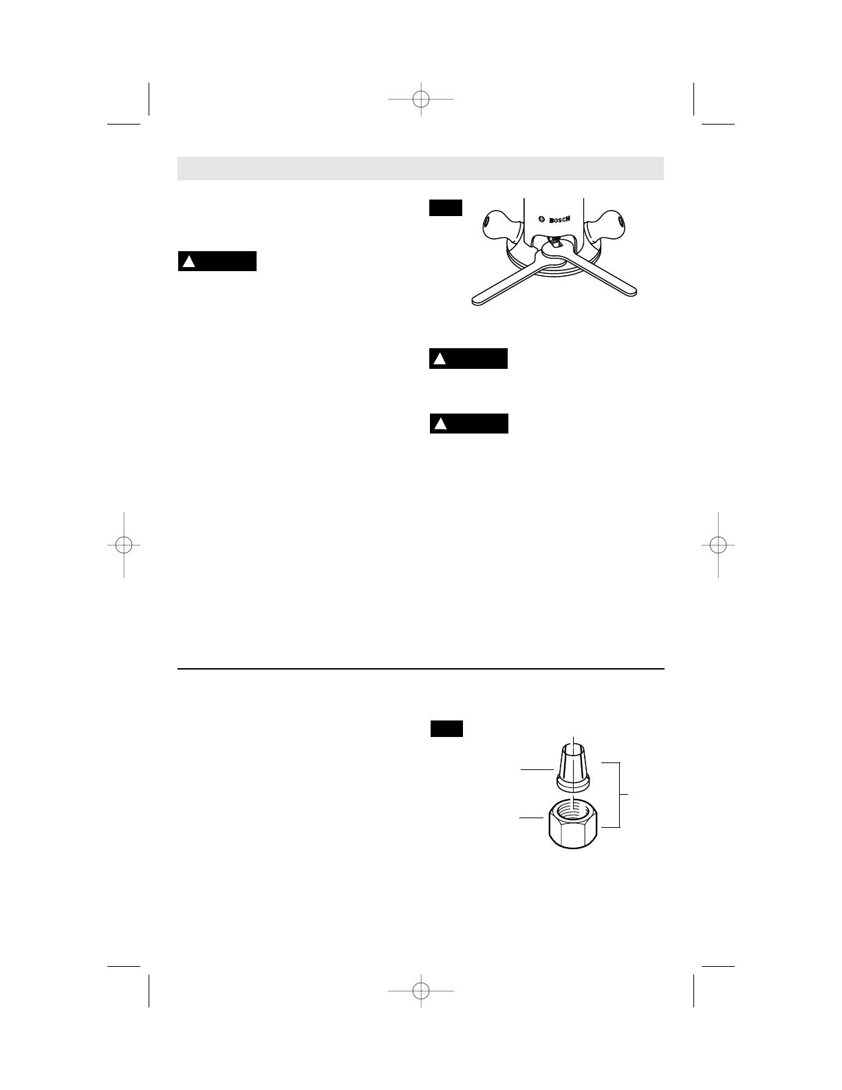
1. Remove the chip shield (or flip up if plunge
base is attached.
2. Hold the armature shaft in place with the
shaft wrench (Fig. 4)
3. Next, use the collet wrench to loosen the
collet chuck assembly in counter-clockwise
direction (viewed from under the router).
4. Insert the shank of the router bit into the
collet chuck assembly as far as it will go,
then back the shank out until the cutters are
approximately 1/8" to 1/4" away from the
collet nut face.
5. With the router bit inserted and the shaft
wrench holding the armature shaft, use the
collet wrench to firmly tighten the collet
chuck assembly in a clockwise direction
(viewed from under the router). To ensure
proper gripping of the router bit and
minimize run-out, the shank of the router bit
must be inserted at least 5/8".
When the templet guide has
been removed from base, do
not use router bits greater than 2" in
diameter as they will not fit through the sub-
base.
To prevent damage to tool,
do not tighten collet without
a bit.
NOTE: The bit shank and chuck should be
clean and free of dust, wood, residue and
grease before assembling.
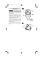
REMOVING THE ROUTER BIT
1. Use the shaft and collet chuck wrenches as
described earlier, and turn the collet chuck
assembly in a counter-clockwise direction.
2. Once the collet chuck assembly is loosened
continue to turn the collet chuck assembly
until it pulls the collet free from its taper, and
the router bit can be removed.
NOTE: The collet chuck is self-extracting; it is
NOT necessary to strike the collet chuck to free
the router bit.
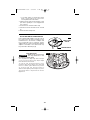
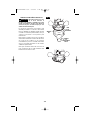
COLLET CHUCK CARE
With the router bit removed, continue to turn
the collet chuck counter-clockwise until it is
free of the shaft. To assure a firm grip,
occasionally blow out the collet chuck with
compressed air, and clean the taper in the
armature assembly shaft with a tissue or fine
brush. The collet chuck is made up of two
component parts as illustrated (Fig. 5); check to
see that the collet is properly seated in the
collet chuck nut and lightly thread the collet
chuck back onto the armature shaft. Replace
worn or damaged collet chucks immediately.
!
WARNING
SHAFT
WRENCH
COLLET
WRENCH
!
CAUTION
COLLET
COLLET
NUT
!
WARNING
FIG. 4
FIG. 5
COLLET
CHUCK
BM 2610908996 5/03 5/20/03 9:06 AM Page 8
-9-
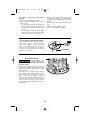
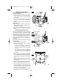
REMOVING MOTOR FROM BASE
To remove motor from non-plunge bases:
(Fig. 6)
1. Hold router in horizontal position, open base
clamp lever, depress coarse adjustment
lever, and pull motor upwards until it stops.
2. Turn motor counter-clockwise, and gently
pull it free of base.
To remove motor from plunge base: (Fig. 7)
1. Hold router in horizontal position, open base
clamp lever, and pull motor upwards until it
stops.
2. Turn motor counter-clockwise, and gently
pull it free of base.
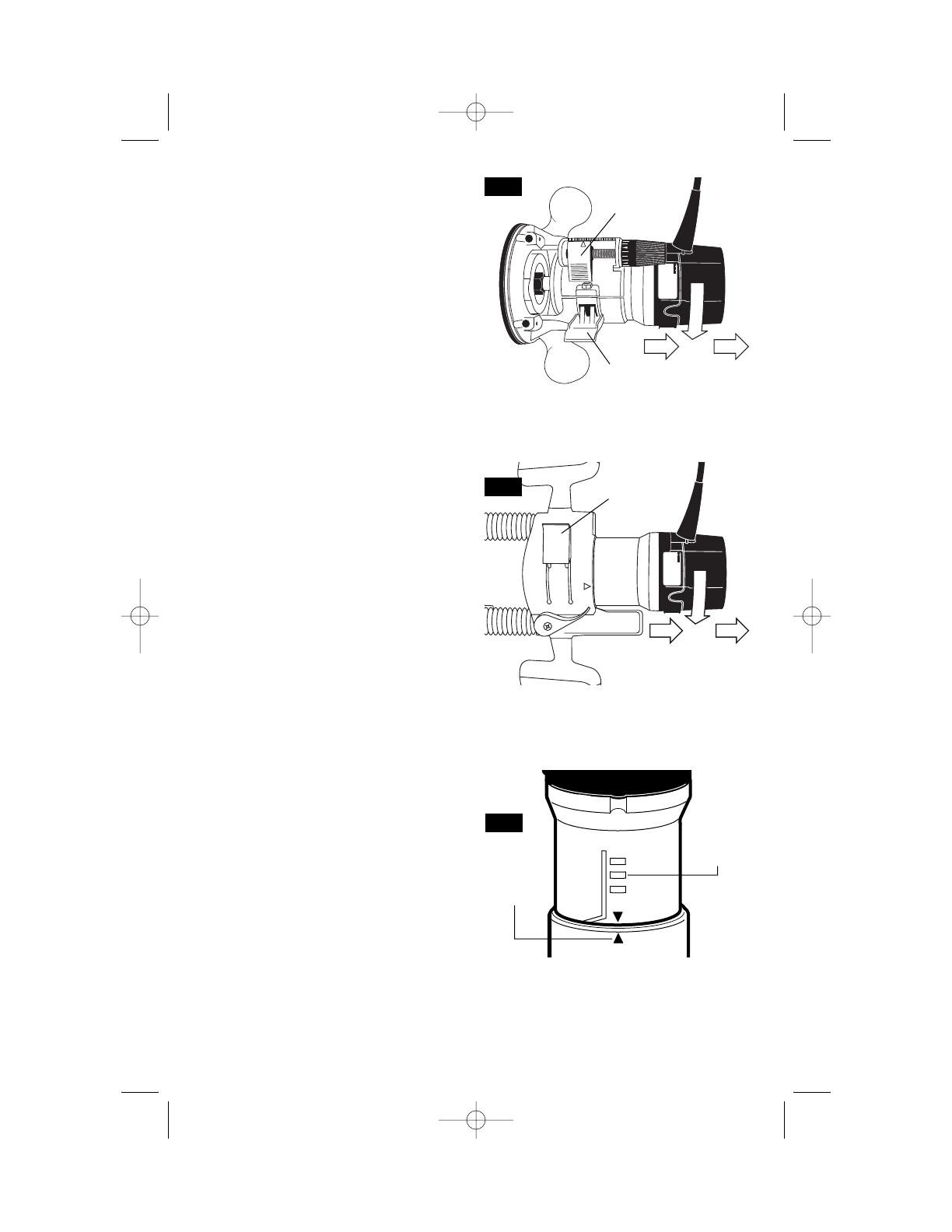
INSTALLING MOTOR IN BASE
The motor can be installed with the switch
positioned on the right or left of the base from
the operator's side (and the cord facing the
opposite side of the router). Install the motor so
that the switch is in the location you find to be
the most easily accessible from the handles.
The switch should be easier to turn "OFF" than
"ON" in case of an emergency.
To install motor in non-plunge base:
1. Release the base clamp lever.
2. Line up the arrow on the base with arrow on
the motor. (Fig. 8)
• To position switch on the right side of the
base, line up the base’s arrow with motor
housing’s arrow that is below the cord.
• To position switch on the left, line up the
base’s arrow with motor housing’s arrow
that is below the switch.
3. While pressing the coarse adjustment lever,
slide motor into base until resistance in felt.
(The base’s guide pin is now engaged into
slot on motor.)
4. Continue to press coarse adjustment lever,
and turn the motor clockwise until it stops.
5. Push the motor into the base until it reaches
the approximate desired depth.
6. Release the coarse adjustment lever and
slide the motor forward or back as needed
until the coarse adjustment system’s “catch”
springs into the coarse adjustment detent
notch.
7. Set final height position as described below
in “Operating Instructions”.
To install motor in plunge base:
1. Release the base clamp lever.
2. Line up the arrow on the base with arrow on
the motor. (Fig. 8)
• To position switch on the right side of the
base, line up the base’s arrow with arrow
on the motor housing that is below the
cord.
ALIGNMENT
ARROWS
COARSE
ADJUSTMENT
NOTCHES
MOTOR
BASE
FIG. 8
BASE
CLAMP
LEVER
FIG. 6
BASE
CLAMP
LEVER
FIG. 7
COARSE
ADJUSTMENT
LEVER
BM 2610908996 5/03 5/20/03 9:06 AM Page 9

CHIP DEFLECTOR
Always wear eye protection.
The chip deflector is not
intended as a safety guard.
The chip deflectors help keep dust and chips
out of your face, it will not stop objects larger
than dust thrown from the bit.
To remove chip shield from bases, press
inward on tabs until it releases from base and
remove. To attach, place deflector into position
as shown in (Fig. 10). Then flex sides of
deflector while pushing until it snaps into place.
The plunge base’s chip shield can also be
flipped out.
INSTALLING TEMPLET GUIDE ADAPTER
Place templet guide adapter over the holes in
the center of the sub-base, and align the two
threaded holes in the bottom of adapter with
the countersunk holes in sub-base. Fasten
adapter with the screws provided. Note that the
adapter is reversible, so the release lever may
be positioned as desired. (Fig. 9)
-10-
TEMPLET GUIDE
ADAPTER
MOUNTING SCREWS
FIG. 9
FIG. 10
!
WARNING
• To position switch on the left, line up the
base’s arrow with arrow on the motor
housing that is below the switch.
3. Slide motor into base until resistance in felt.
(The base’s guide pin is now engaged into
slot on motor.)
4. Turn the motor clockwise until it stops.
5. Push the motor into the base as far as it will
go.
6. Fasten the base clamp lever.
BM 2610908996 5/03 5/20/03 9:06 AM Page 10

Bosch routers are designed for speed,
accuracy and convenience in performing
cabinet work, routing, fluting, beading, cove-
cutting, dove tails, etc. They will enable you to
accomplish inlay work, decorative edges and
many types of special carving.
DEPTH ADJUSTMENT
WITH FIXED BASE
Your router is equipped with a true micrometer
type fine adjustment mechanism, which can be
used in any position and provides precise
adjustment of the router bit position for
unmatched accuracy. When the tool is lowered
to the approximate position desired, this device
may be adjusted to precisely set the final bit
position.
Your router also features three horizontal
notches on both sides of the motor housing for
coarse adjustments. The notches are spaced
1/2" apart which allows you to quickly lower or
raise the tool depth in three 1/2" increments.
(Approximately 12.7 mm), by simply depressing
the coarse adjustment release lever.
TO ADJUST DEPTH
NOTE: All depth adjustments must be made
with the base clamp lever released.
1. Hold the tool in a horizontal position with the
base clamp lever facing you.
2. Open the base clamp lever to release the
motor.
3. COARSE ADJUSTMENT:
To make a large depth adjustment, depress
coarse adjustment release lever and raise or
lower to desired depth. There are three notches
in the motor housing which are spaced 1/2" to
facilitate this adjustment.
4. FINE DEPTH ADJUSTMENT:
To use the fine adjustment feature, turn the fine
adjustment knob clockwise to lower the router
bit or counter-clockwise to raise it.
NOTE: Be sure coarse adjustment lever is
engaged in one of the coarse adjustment
notches before making a fine adjustment.
To allow precise settings, the indicator ring is
graduated in English and Metric increments.
(Note: one full turn of fine adjustment knob =
1/16" or approximately 1.5 mm. The fine
adjustment mechanism has a total adjustment
range of 7/8" (23 mm). Each cast indicator mark
next to coarse adjustment lever is equal to 1/8"
To prevent damage to tool, avoid wedging the
coarse adjustment lever against the upper A or
lower B portion of the housing as shown in
figure 11.
5. After making depth adjustments, re-clamp
the motor.
The indicator ring may be reset to zero without
moving the fine adjustment knob, to allow the
user to begin the adjustment from any
reference point desired.
-11-
Operating Instructions
A
B
FINE ADJUSTMENT DIAL
BASE CLAMP LEVER
COARSE
ADJUSTMENT
LEVER
INDICATOR RING
FIG. 11
CAST INDICATOR MARKS
BM 2610908996 5/03 5/20/03 9:06 AM Page 11
-12-
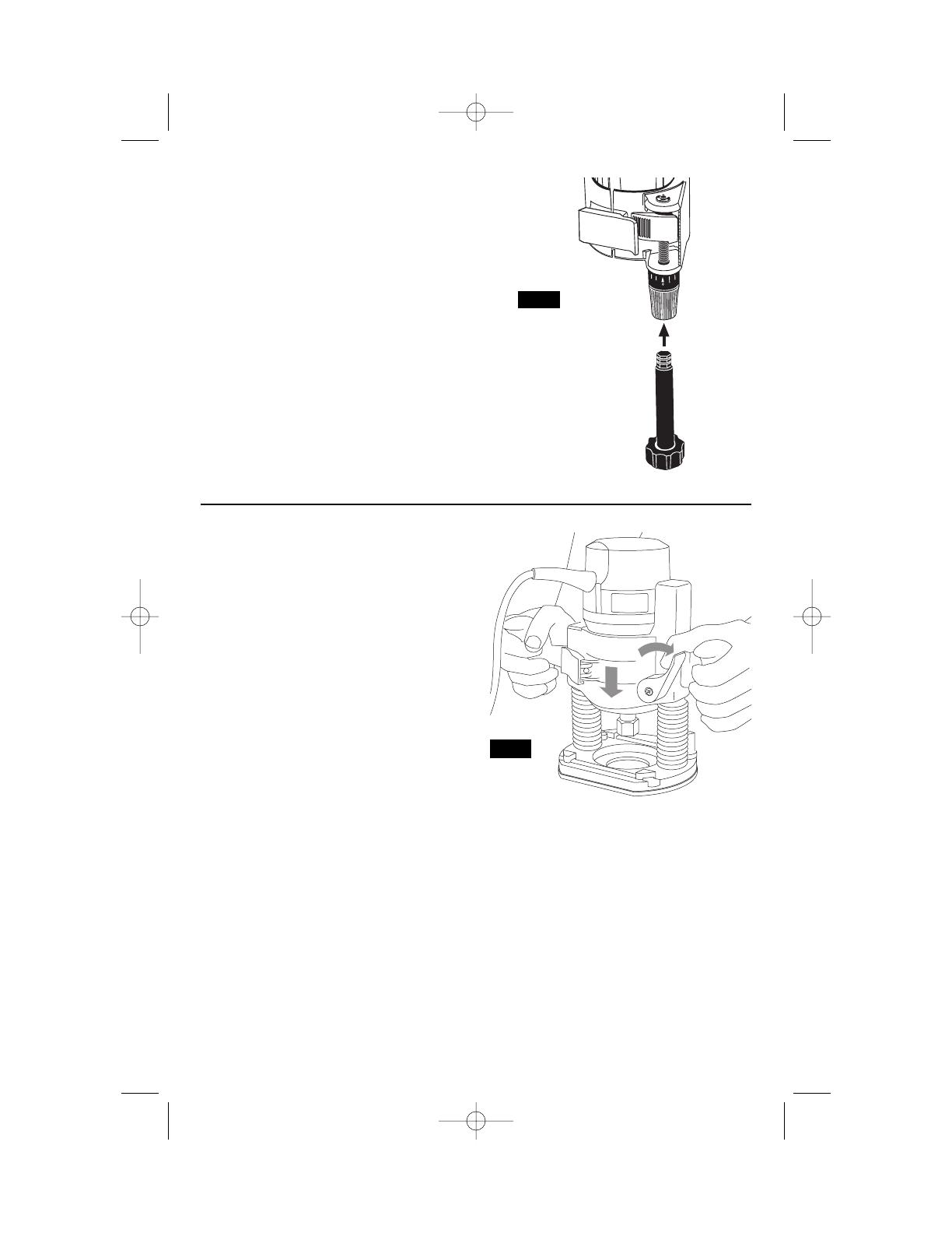
The RA1002 Fine Adjustment Control
Extension, an optional accessory for the non-
plunge bases, allows fine adjustment from
beyond the top of the motor housing. To install,
simply press the RA1002 into the end of the
base’s own fine adjustment knob. (Fig. 12)
TO CLAMP MOTOR
When final coarse and fine adjustments have
been made, fasten the base clamp lever to
secure adjustments. (If additional clamping
force is desired: using a 10 mm wrench, rotate
clamp nut clockwise SLIGHTLY (1/8 turn or
less), then test clamp. Do not over-tighten.)
DEEP CUTS
For deeper cuts, make several progressively
deeper cuts by starting at one depth and then
make several subsequent passes, increasing
the cutting depth with each pass.
To be certain that your depth settings are as
desired, you may want to make test cuts in
scrap material before beginning work.
FIG. 12
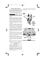
DEPTH ADJUSTMENT WITH PLUNGE BASE
PLUNGING ACTION
The plunge feature simplifies depth
adjustments and will allow the cutting bit to
easily and accurately enter the workpiece. To
lower, push plunge lock lever to the left, apply
downward pressure until you reach desired
depth, and release pressure on lever to lock
(Fig. 13). The plunge lock lever is spring loaded
and returns automatically to the locked
position. To raise the router, push plunge lock
lever to the left, release pressure on router and
the router will automatically retract the bit from
the workpiece. It is advisable to retract the bit
whenever it is not engaged in workpiece.
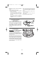
DEPTH ROD AND TURRET
The depth rod and the depth stop turret are
used to control cutting depth as follows;
1. With the bit installed, gently lower the motor
until the tip of the router bit just contacts the
level surface the router is sitting on. This is
the “zero” position, from which further depth
adjustments can be accurately made.
2. To set a desired depth of cut, rotate depth
stop turret until the lowest step is aligned
with the depth rod. Loosen depth indicator
knob and lower the depth rod until it contacts
the lowest step of the turret. Slide the depth
indicator until the red line indicates zero on
the depth scale, indicating the point at which
the bit just contacts the work (Fig. 14).
3. To set a desired cutting depth, slide the
depth rod up until the red depth indicator line
attains the desired cutting depth, and secure
the rod in position by firmly tightening the
depth indicator knob.
4. The desired depth of cut may now be
achieved by plunging the router until the
depth rod contacts the selected stop on the
turret.
DEEP CUTS
For deeper cuts, make several progressively
deeper cuts by starting with the highest step on
the depth turret, and after each cut, rotate the
depth turret to progressively lower steps as
FIG. 13
BM 2610908996 5/03 5/20/03 9:06 AM Page 12

desired, until the final depth (lowest step or flat)
is reached. Steps progress by 1/8” increments.
To be certain that your depth settings are as
desired, you may want to make test cuts in
scrap material before beginning work.
FINE ADJUSTMENT
The RA1166 plunge base is equipped with a
fine adjustment system that allows you to micro
adjust the plunge depth of the router bit for
superior routing accuracy.
Each complete revolution of the fine adjustment
stop adjusts the plunging depth by 1/32”, and
each of the four indicator marks on the knob
represents 1/128”. One of the four tick marks is
larger than the other to indicate a complete
revolution. A reference indicator line is built in
to the depth rod.
To use the fine adjustment knob, once the
depth rod and turret have been set, check the
final depth setting and fine-adjust as follows:
To micro-increase the plunge depth, raise the
fine adjustment stop by turning it counter-
clockwise by the desired amount.
To micro-reduce the plunge depth, lower the
fine adjustment stop by turning it clockwise by
the desired amount.
Notes:
• When micro-adjusting the plunge depth, it is
more convenient to move the fine adjustment
stop up than down. Before setting the depth
rod and turret, make sure the fine adjustment
stop has been turned several revolutions
down from its top position so that it can be
adjusted upward.
• The fine adjustment stop cannot be use to
reduce the plunge depth when the depth rod
is already touching the depth stop turret. The
router must be raised before such an
adjustment can be made.
-13-
2
1
0
IN
50
40
30
20
10
0
MM
FIG. 14
DEPTH INDICATOR
KNOB
DEPTH
INDICATOR
DEPTH ROD
DEPTH STOP
TURRET
DEPTH ROD FINE
ADJUSMENT KNOB
BM 2610908996 5/03 5/20/03 9:06 AM Page 13

-14-
ROCKER “ON/OFF” SWITCH
Your tool can be turned “ON” or “OFF” by the
rocker switch located on the motor housing.
One side of the switch is marked “I” for “ON“,
and the other side of switch is marked “O” for
“OFF“. Also the edge of switch displays red
when switch is in the “ON“ position.
TO TURN THE TOOL “ON”: Push the side of
the switch marked “I”.
TO TURN THE TOOL “OFF”: Push the side of
the switch marked “O”.
Always hold the router off the work when
turning the switch on or off. Contact the work
with the router after the router has reached full
speed, and remove it from the work before
turning the switch off. Operating in this manner
will prolong switch and motor life and will
greatly increase the quality of your work (Fig. 1).
ROCKER POWER "ON-OFF" WITH TRIGGER
SWITCH AND "LOCK-ON"BUTTON
(Models 1618 & 1618EVS only)
The power is switched "ON" by the rocker
switch located on the top of the motor housing
as described above. Now your tool can be
turned "ON" or "OFF" by squeezing or
releasing the trigger. Your tool is also equipped
with “Lock-ON” button located just above the
trigger that allows continuous operation without
holding the trigger (Fig. 2).
TO LOCK SWITCH ON: Squeeze trigger,
depress button and release trigger.
TO UNLOCK THE SWITCH: Squeeze trigger
and release it without depressing the “Lock-
ON” button.
If the “Lock-ON” button is
continuously being
depressed, the trigger cannot be released.
On models 1617 & 1618 hold the tool with both
hands while starting the tool, since torque from
the motor can cause the tool to twist.
SOFT START FEATURE
(Models 1617EVS & 1618EVS only)
Electronic feedback control minimizes torque
twist customary in larger routers by limiting the
speed at which motor starts.
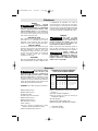
ELECTRONIC VARIABLE SPEED CONTROL
(Models 1617EVS & 1618EVS only)
The electronic speed control feature allows
motor speed to be matched to cutter size and
material hardness for improved finish, extended
bit life, and higher performance. Speed
changes are achieved by rotating Control Dial
RIGHT to increase speed, LEFT to decrease as
indicated on housing (Fig. 1). Speed may be
changed while tool is on. The reference
numbers on the dial facilitate re-setting control
to desired speed.
The speed chart indicates the relationship
between settings and application, exact
settings are determined by operator experience
and preference. The bit manufacturer may also
have a speed recommendation.
CONSTANT RESPONSE™ CIRCUITRY
(Models 1617EVS & 1618EVS only)
The router's Constant Response™ Circuitry
monitors and adjusts power to maintain the
desired RPM for consistent performance and
control.
!
WARNING
DIAL
SETTING RPM APPLICATION
1 8,000
2 13,500
3 16,500
4 20,000
5 21,500
6 25,000
}
}
Nonferrous metals,
larger diameter bits,
and cutters
Softwoods, plastics,
counter tops, smaller
diameter bits, and
cutters
BM 2610908996 5/03 5/20/03 9:06 AM Page 14

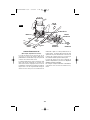
FEEDING THE ROUTER
As seen from the top of the router, the bit
turns clockwise and the cutting edges face
accordingly. Therefore, the most efficient cut
is made by feeding the router so that the bit
turns into the work, not away. Figure 15
shows proper feed for various cuts. How fast
you feed depends on the hardness of the
material and the size of the cut. For some
materials, it is best to make several cuts of
increasing depth.
If the router is hard to control, heats up, runs
very slowly or leaves an imperfect cut,
consider these causes:
1. Wrong direction of feed — hard to control.
2. Feeding too fast — overloads motor.
3. Dull bit — overloads motor.
4. Cut is too large for one pass — overloads
motor.
5. Feeding too slow — leaves friction burns
on work.
Feed smoothly and steadily (do not force).
You will soon learn how the router sounds
and feels when it is working best.
RATE OF FEED
When routing or doing related work in wood
and plastics, the best finishes will result if
the depth of cut and feed rate are regulated
to keep the motor operating at high speed.
Feed the router at a moderate rate. Soft
materials require a faster feed rate than hard
materials.
The router may stall if improperly used or
overloaded. Reduce the feed rate to prevent
possible damage to the tool. Always be sure
the collet chuck is tightened securely before
use. Always use router bits with the shortest
cutting length necessary to produce the
desired cut. This will minimize router bit run-
out and chatter.
-15-
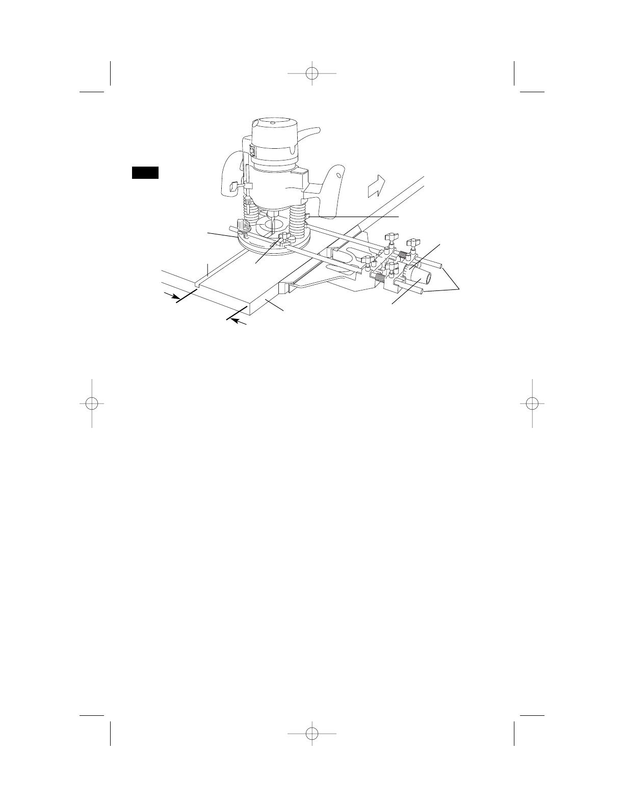
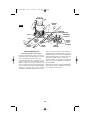
GUIDING THE ROUTER
The router can be guided through the work
in any of several ways. The method you use
depends, of course, on the demands of the
particular job and on convenience.
For routing operations such as grooving or
dadoing, it is often necessary to guide the
tool in a line parallel to a straight edge. One
method of obtaining a straight cut is to
securely clamp a board or other straightedge
to the work surface, and guide the edge of
the router sub-base along this path (Fig. 16).
FIG. 15
FIG. 16
BIT
WORK
DIRECTION OF
ROUTER FEED
START
HERE
BOARD GUIDE
SECURELY CLAMP
BOARD GUIDE
FEED
DIRECTION
BM 2610908996 5/03 5/20/03 9:06 AM Page 15
CENTERING THE SUB-BASE AND
TEMPLET GUIDES
Your router features the Bosch “Precision
Centering Design”. Its sub-base is precisely
centered at the factory. This positions the bit at
the center of the sub-base and optional templet
guides. Precision centering allows you to
closely follow jigs such as straight guides,
templets, and dovetail fixtures without worrying
about bit walk-off from the intended cut line for
any reason, including the orientation of the
router’s handles.
In the event the sub-base screws are loosened
or removed, such when preparing the router for
use in a router table, here's how to re-center
the sub-base when reattaching it:
To quickly re-center the sub-base, attach the
sub-base using the set of flathead screws
(included) and the countersunk screw holes in
the sub-base. (Flathead screws have the
tapered heads.) The flathead screws and
countersunk holes will pull the sub-base into a
position that is very close to centered.
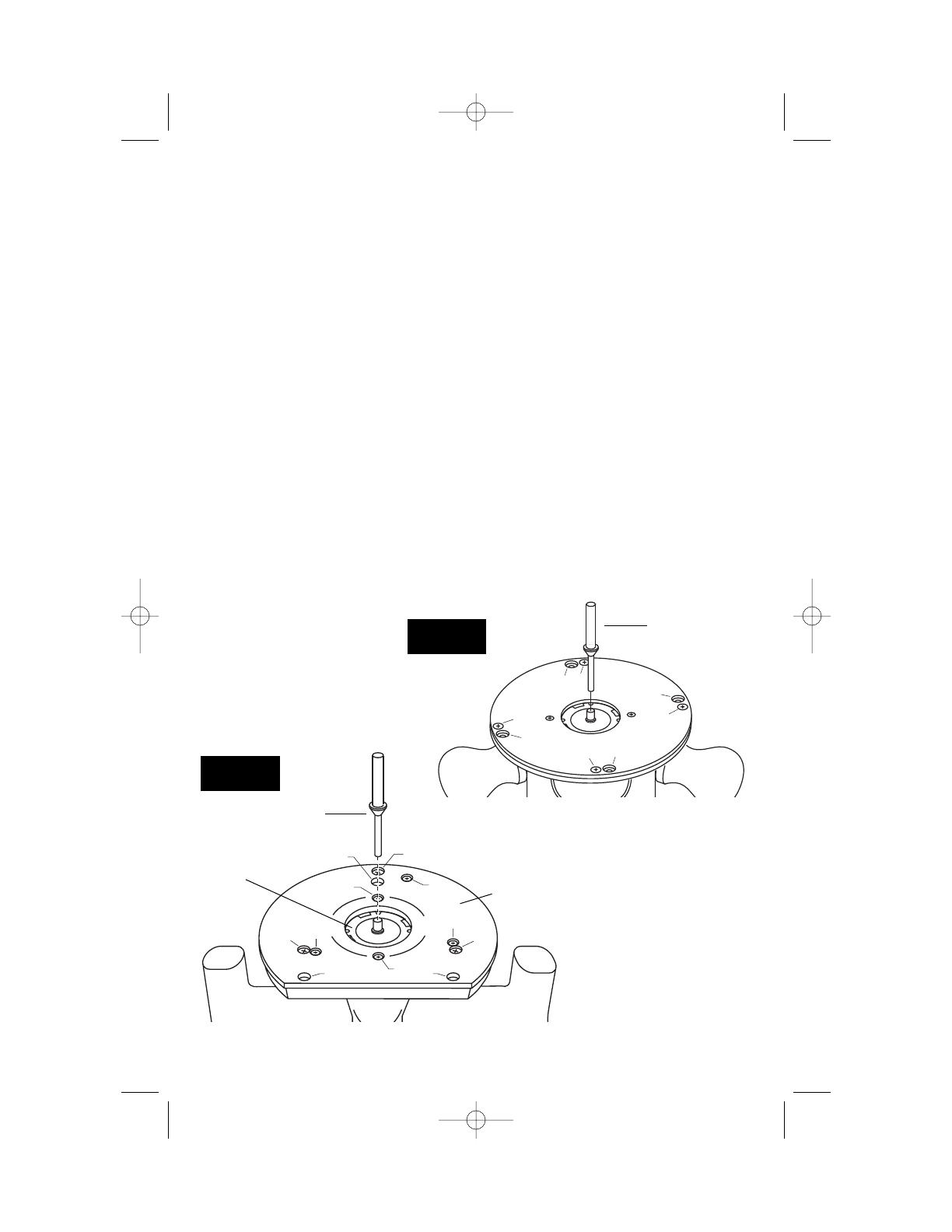
OR — To most precisely re-center the sub-
base, attach the sub-base using the optional
Bosch centering cone, an optional Bosch
templet guide, and the set of pan-head screws
(included). (Pan-head screws have rounded
tops.) Follow steps 1-8.
1. Position the sub-base so that its pan-head
screw holes are over the matching set of
threaded holes in the base.
2. Insert the pan-head screws, not the flathead
screws, through the sub-base and tighten
them until they are snug, but still allow the
sub-base to move.
3. Insert templet guide (optional accessory) the
installed template guide adapter as
described elsewhere in this manual.
4. Slide centering cone (optional accessory)
through templet guide and into collet. Use
narrow end of cone when inserting into 1/4”
collet, wider end of cone when inserting into
1/2” collet.
5. Tighten collet nut with fingers to put slight
grip on centering cone.
6. Lightly press centering cone into templet
guide to center guide and sub-base.
7. Tighten the pan-head screws.
8. Remove centering cone. The precision
centering of the templet guide and sub-base
is complete.
-16-
A
B
A
C
A
C
A
B
B
B
CENTERING CONE
(optional accessory)
D D
B
A
B
A
B
A
C
C
D
FIG. 17
PLUNGE BASE
FIG. 18
OTHER BASES
CENTERING CONE
(optional accessory)
TEMPLET
GUIDE
(optional
accessory)
SUB-BASE
A = COUNTERSUNK SCREW HOLES
B = PAN-HEAD SCREW HOLES
C = TEMPLET GUIDE ADAPTER
SCREW HOLES
D = HOLES FOR ATTACHING
ROUTER TO ROUTER TABLE
MOUNTING PLATE
(Under sub-base on
non-plunge bases)
BM 2610908996 5/03 5/20/03 9:06 AM Page 16
-17-
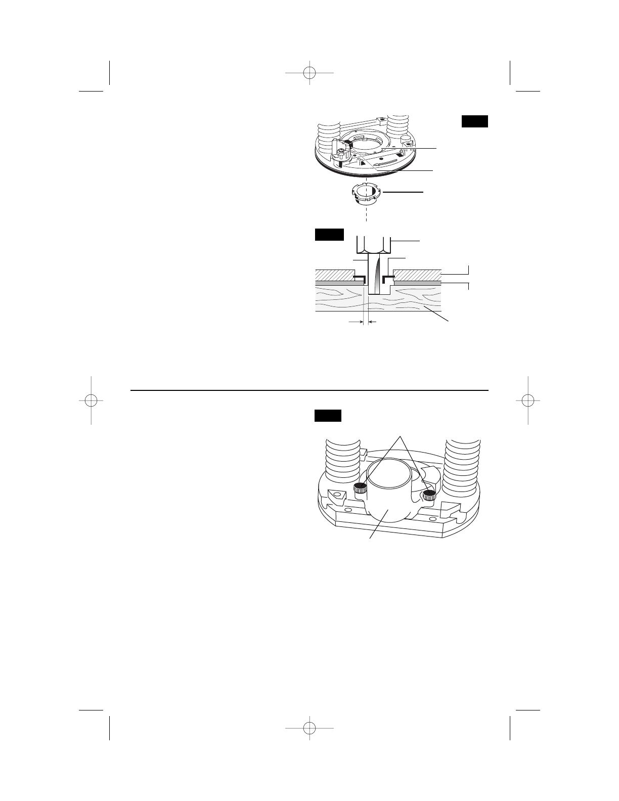
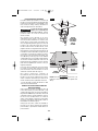
TEMPLET GUIDES
The router is equipped with an exclusive
quick-change templet guide adapter, which
firmly grips the guides with a spring-loaded
ring. To insert or change the templet guide,
retract the templet guide release lever. Align
the cutaways on the templet guide with the
tabs on the bottom of the templet guide
adapter. Insert the templet guide and release
the lever to grip the templet guide in place
(Fig. 19).
Templet guides are used with a number of
special accessories, such as hinge templets,
which are listed in your BOSCH catalog. In
addition, special templets are easily
prepared for cutting repeated patterns,
special designs, inlays, and other
applications. A templet pattern may be made
of plywood, hardboard, metal or even
plastic, and the design can be cut with a
router, jigsaw, or other suitable cutting tool.
Remember that the pattern will have to be
made to compensate for the distance
between the router bit and the templet guide
(the “offset”), as the final workpiece will differ
in size from the templet pattern by that
amount, due to the bit position (Fig. 20).
Also available as an optional accessory is an
additional adapter, the RA1100, that allows
use of conventional threaded templet guides
with the Bosch quick-release system.
TEMPLET GUIDE
(optional accessory)
TEMPLET GUIDE
ADAPTER
TEMPLET GUIDE
RELEASE LEVER
FIG. 19
COLLET CHUCK
WORKPIECE
ROUTER BIT
OFFSET
TEMPLET
GUIDE
TEMPLET
PATTERN
FIG. 20
ROUTER
SUB-BASE
ROUTER DUST COLLECTION
There are three optional dust extraction
hood accessories. Each dust extraction
hood is sized to accept 35mm vacuum
hoses. Each accessory pack includes the
VAC002 adapter that will connect the hood
to 1-1/4” and 1-1/2” vacuum hoses. An
adapter to connect the hood to 2-1/2" hoses
is also available separately.
ROUTER DUST COLLECTION FOR
PLUNGE BASE
The RA1174 dust extraction hood is
designed for use the plunge base (RA1166)
when routing is done in the middle of the
workpiece, such as when creating slots or
routing patterns for inlays. If you have a
shop vacuum system, you can attach the
dust extraction hood for improved visibility,
accuracy and utility, particularly in freehand
routing.
To attach, position as shown and secure
adapter to base with the thumbscrews
provided (Fig. 21).
The dust extraction hood can also be
installed with the hose outlet facing the front
of the tool. If the templet guide adapter is
installed, it will need to be reversed or
removed to allow the release lever to fit
under the dust hood.
FIG. 21
DUST EXTRACTION HOOD
(Optional Accessory)
4mm THUMB
SCREWS
BM 2610908996 5/03 5/20/03 9:06 AM Page 17

-18-
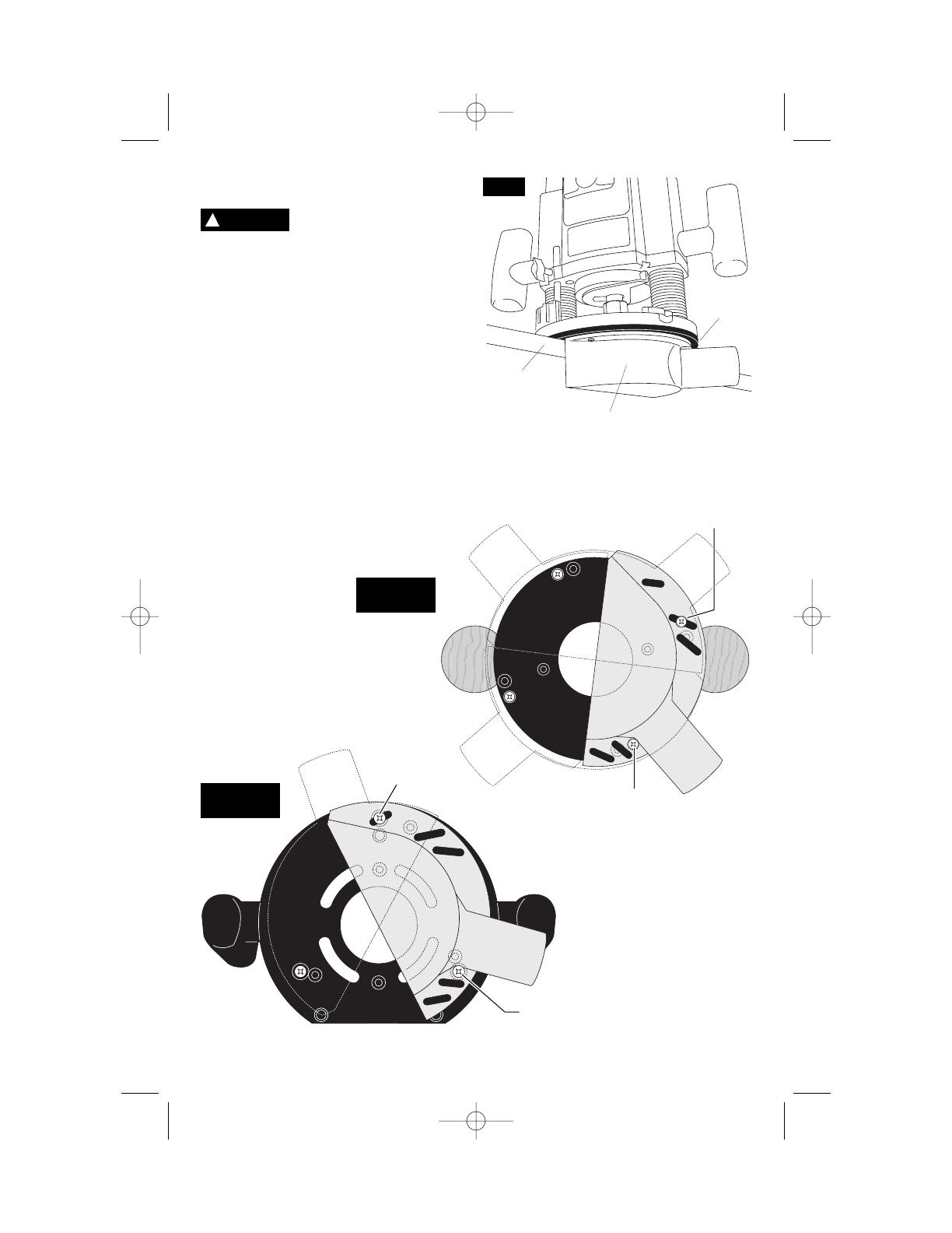
RA1171 DUST EXTRACTION HOOD FOR
OTHER BASES
Do not reach in area of the
bit while the router is ON
or plugged in. To avoid entangling hoses,
do not use this dust extraction hood at
the same time as any other dust
extraction hood.
The RA1171 dust extraction hood is
designed for use with Bosch routers bases
“S” (RA1160) and “D” (RA1162), when the
routing is done in the middle of the
workpiece, such as when creating slots or
routing out patterns for inlays.
To attach the hood to the router base, slide
the hood into the backside of the router
base with the hood’s rounded corners facing
up (Fig. 22 & 23). Securely tighten the two
knurled thumbscrews.
For maximum dust collection effectiveness,
make sure the router’s chip shield is in
place.
!
WARNING
DUST
EXTRACTION
HOOD
(Optional Accessory)
M5
SCREW
ROUTER
BASE
FIG. 22
FIG. 23
BM 2610908996 5/03 5/20/03 9:06 AM Page 18
-19-
RA1170 EDGEFORMING DUST
EXTRACTION HOOD
Do not reach in area of the
bit while the router is ON
or plugged in. To avoid entangling hoses,
do not use this dust extraction hood at
the same time as any other dust
extraction hood.
The RA1170 dust extraction hood (optional
accessory) is used for dust collection when
edge-forming (Fig. 24).
ATTACHING DUST EXTRACTION HOOD
You can attach the edge-forming hood in
several places according to your needs or
preferences. This hood is attached using two
of the screw holes on the router base that
are used to attach the router’s sub-base.
Choose the desired location for the hood.
Loosen and take out the two screws from
the router base and attach the dust
extraction hood — over the router’s sub-
base — using the screws provided with the
hood. Securely tighten the screws. (Figures
25 & 26).
DUST
EXTRACTION
HOOD
ROUTER
SUB-BASE
WORKPIECE
EDGE
!
WARNING
4mm x 16mm
SCREW
4mm x 16mm
SCREW
4mm x 16mm
SCREW
SUB-BASE
DUST
EXTRACTION
HOOD
4mm x 16mm
SCREW
FIG. 24
DUST
EXTRACTION
HOOD
FIG. 25
PLUNGE BASE
FIG. 26
OTHER BASES
BM 2610908996 5/03 5/20/03 9:06 AM Page 19
-20-
DELUXE ROUTER GUIDE
(Not included, available as accessory)
The Bosch deluxe router guide is an optional
accessory that will guide the router parallel
to a straight edge or allow you to create
circles and arcs.
The deluxe router guide is supplied with two
rods and screws to fasten the guide (Fig.
27). In addition, it features a fine adjustment
knob and indicator for accurately positioning
the edge guide relative to the bit. With the
guide installed and adjusted, the router
should be fed normally, keeping the guide in
contact with the edge of the workpiece at all
times. The deluxe router guide may also be
positioned directly under the router base for
operations where a cut is needed close to or
at the edge of the work.
The deluxe router guide includes a dust
extraction hood and the VAC002 vacuum
hose adapter.
For complete instructions on installation and
operation, please refer to the instructions
which are included with this accessory.
FIG. 27
DESIRED
WIDTH
CUT
BASE
WORKPIECE
ROUTER
GUIDE
RODS
6mm WING
SCREW
6mm WING SCREW
FINE
ADJUSTMENT
KNOB
FINE ADJUSTMENT
INDICATOR
FEED
DIRECTION
BM 2610908996 5/03 5/20/03 9:06 AM Page 20
Page is loading ...
Page is loading ...
Page is loading ...
Page is loading ...
Page is loading ...
Page is loading ...
Page is loading ...
Page is loading ...
Page is loading ...
Page is loading ...
Page is loading ...
Page is loading ...
Page is loading ...
Page is loading ...
Page is loading ...
Page is loading ...
Page is loading ...
Page is loading ...
Page is loading ...
Page is loading ...
Page is loading ...
Page is loading ...
Page is loading ...
Page is loading ...
Page is loading ...
Page is loading ...
Page is loading ...
Page is loading ...
Page is loading ...
Page is loading ...
Page is loading ...
Page is loading ...
Page is loading ...
Page is loading ...
Page is loading ...
Page is loading ...
Page is loading ...
Page is loading ...
Page is loading ...
Page is loading ...
Page is loading ...
Page is loading ...
Page is loading ...
Page is loading ...
Page is loading ...
Page is loading ...
Page is loading ...
Page is loading ...
-
 1
1
-
 2
2
-
 3
3
-
 4
4
-
 5
5
-
 6
6
-
 7
7
-
 8
8
-
 9
9
-
 10
10
-
 11
11
-
 12
12
-
 13
13
-
 14
14
-
 15
15
-
 16
16
-
 17
17
-
 18
18
-
 19
19
-
 20
20
-
 21
21
-
 22
22
-
 23
23
-
 24
24
-
 25
25
-
 26
26
-
 27
27
-
 28
28
-
 29
29
-
 30
30
-
 31
31
-
 32
32
-
 33
33
-
 34
34
-
 35
35
-
 36
36
-
 37
37
-
 38
38
-
 39
39
-
 40
40
-
 41
41
-
 42
42
-
 43
43
-
 44
44
-
 45
45
-
 46
46
-
 47
47
-
 48
48
-
 49
49
-
 50
50
-
 51
51
-
 52
52
-
 53
53
-
 54
54
-
 55
55
-
 56
56
-
 57
57
-
 58
58
-
 59
59
-
 60
60
-
 61
61
-
 62
62
-
 63
63
-
 64
64
-
 65
65
-
 66
66
-
 67
67
-
 68
68


Bosch 1617 User manual
- Category
- Power tools
- Type
- User manual
Ask a question and I''ll find the answer in the document
Finding information in a document is now easier with AI
in other languages
- français: Bosch 1617 Manuel utilisateur
- español: Bosch 1617 Manual de usuario
Related papers
-
Bosch RA1181+1617EVS User manual
-
-
-
-
Bosch Power Tools 1617EVSPKRA1181 User manual
-
-
-
Bosch Power Tools PR20EVSK User manual
-
-