E-flite Habu 32x DF User manual
- Category
- Remote controlled toys
- Type
- User manual

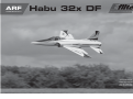
ARF
ALMOST-READY-TO-FLY
Habu 32x DF
Instruction Manual
Bedienungsanleitung
Manuel d’utilisation
Manuale di Istruzioni

2
EFL Habu 32x DF
•SAFETY WARNINGS AND
PRECAUTIONS
Read and follow all instructions and safety precautions
before use. Improper use can result in fi re, serious injury
and damage to property.
Components
Use only with compatible components. Should any
compatibility questions exist, please refer to the product
instructions, component instructions or contact the
appropriate Horizon Hobby offi ce.
Flight
Fly only in open areas to ensure safety. It is
recommended fl ying be done at radio control fl ying
fi elds. Consult local ordinances before choosing a fl ying
location.
Propeller
Keep loose items that can become entangled in
the propeller away from the prop. This includes
loose clothing or other objects such as pencils and
screwdrivers. Keep your hands away from the propeller
as injury can occur.
Batteries
Always follow the manufacturer’s instructions when using
and disposing of any batteries. Mishandling of Li-Po
batteries can result in fi re causing serious injury and
damage.
Small Parts
This kit includes small parts and should not be left
unattended near children as choking and serious injury
could result.
•SAFE OPERATING
RECOMMENDATIONS
• Inspect your model before every fl ight to ensure it is
airworthy.
• Be aware of any other radio frequency user who may
present an interference problem.
• Always be courteous and respectful of other users in
your selected fl ight area.
• Choose an area clear of obstacles and large enough to
safely accomodate your fl ying activity.
• Make sure this area is clear of friends and spectators
prior to launching your aircraft.
• Be aware of other activities in the vicinity of your fl ight
path that could cause potential confl ict.
• Carefully plan your fl ight path prior to launch.
• Abide by any and all established AMA National Model
Aircraft Safety Code.
•REGARDING MOTOR AND
BATTERY SELECTION
This model has been tested using the components
listed in the Power Systems section of this manual.
Using components that exceed the output of the listed
components may place excessive loads on the airframe.
This could result in the failure of the airframe in high-
speed or high-load situations.
NOTICE
All instructions, warranties and other collateral documents are subject to change at the sole discretion of Horizon
Hobby, LLC. For up-to-date product literature, visit horizonhobby. com and click on the support tab for this product.
Meaning of Special Language
The following terms are used throughout the product literature to indicate various levels of potential harm when
operating this product:
NOTICE: Procedures, which if not properly followed, create a possibility of physical property damage AND a little
or no possibility of injury.
CAUTION: Procedures, which if not properly followed, create the probability of physical property damage AND a
possibility of serious injury.
WARNING: Procedures, which if not properly followed, create the probability of property damage, collateral
damage, and serious injury OR create a high probability of superfi cial injury.
WARNING: Read the ENTIRE instruction manual to become familiar with the features of the product
before operating. Failure to operate the product correctly can result in damage to the product, personal
property and cause serious injury.
This is a sophisticated hobby product. It must be operated with caution and common sense and requires some
basic mechanical ability. Failure to operate this Product in a safe and responsible manner could result in injury
or damage to the product or other property. This product is not intended for use by children without direct adult
supervision. Do not use with incompatible components or alter this product in any way outside of the instructions
provided by Horizon Hobby, LLC. This manual contains instructions for safety, operation and maintenance. It is
essential to read and follow all the instructions and warnings in the manual, prior to assembly, setup or use, in
order to operate correctly and avoid damage or serious injury.
AGE RECOMMENDATION: NOT FOR CHILDREN UNDER 14 YEARS. THIS IS NOT A
TOY.
•USING THE MANUAL
This manual is divided into sections to help make assembly easier to understand. Boxes () have been placed next
to each step. These help keep track of steps that have been completed.
Page is loading ...
Page is loading ...
Page is loading ...

6
EFL Habu 32x DF
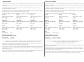
42.0 in (1070mm)
412 sq in (26.6 dm2)
49.5 in (1250mm)
7.05–7.50 lb (3.20–3.40 kg)
•Electric Power•Elektro Antrieb
•Moteur électrique (EP)•Motore elettrico:
DF32 Brushless Motor, 2150Kv
DF32 Brushless Motor, 2150Kv
Moteur brushless DF32, 2150Kv
Motore DF32 Brushless 2150Kv
•Ducted Fan Assembly•Impeller
•Turbine•Gruppo ventola intubata:
Delta-V
®
32 80mm EDF
Delta-V 32 80mm EDF
Delta V 32, 80mm
EDF Delta-V 32 80mm
6-channel (or greater) with 8 servos
6-Kanal (oder größer) mit 8 Servos
6 voies (ou plus) avec 8 servos
a 6 canali (o più) con 8 servo
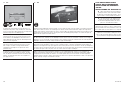
•SPECIFICATIONS•SPEZIFIKATIONEN
•SPÉCIFICATIONS•SPECIFICHE
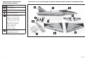
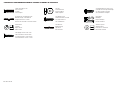
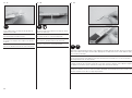
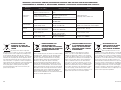
•LARGE PARTS LAYOUT•BAUTEILE (OHNE KLEINTEILE)•GRANDES PIÈCES•SCHEMA DEI COMPONENTI GRANDI
1
3
2
4
5
7
6
9
6
8

7
EFL Habu 32x DF
•REPLACEMENT PARTS•ERSATZTEILE•PIÈCES DE RECHANGE•PEZZI DI RICAMBIO
Part English Deutsch Français Italiano
1. EFL808501 Fuselage with Hatches Rumpf mit Haube Fuselage avec capot Fusoliera con portello
2. EFL808502 Left Wing Panel Tragfl äche links Aile gauche Semiala sinistra
3. EFL808503 Right Wing Panel Tragfl äche rechts Aile droite Semiala destra
4. EFL808504 Horizontal Stabilizer Left and Right Höhenleitwerk links / rechts Stabilisateurs gauche et droit Stabilizzatore orizzontale destro e sinistro
5. EFL808505 Main Canopy Hatch Kabinenhaube Trappe principale Portello principale capottina
6. EFL808506 Plastic Accessories Kunstoffteile Accessoires plastique Accessori in plastica
7. EFL808507 Thrust Tube Schubrohr Tube de tuyère Tubo scarico
8. EFL808515 Rudder with Hinges Seitenruder mit Scharnieren Dérive avec charnières Timone con cerniere
9. EFL808510 Decal Sheet Dekorbögen Planche de décoration Foglio con decalcomanie
•SMALL PARTS (NOT SHOWN)•KLEINTEILE (NICHT ABGEBILDET)•PETITES PIÈCES (NON REPRÉSENTÉES)•PARTI DI PICCOLE DIMENSIONI (NON MOSTRATE)
EFL808508 Hardware Kleinteilepaket Sachet d’accessoires Viti e accessori
EFL808509 Pushrods Schubstangen Tringleries Barrette comandi
EFL808511 Landing Gear Struts Fahrwerksstreben Jambes de train d’atterrissage Gambe carrello
EFL808514 Lower Fan Hatch Untere Impellerabdeckung Trappe inférieure d’accès à la turbine Portello inferiore ventola
•REQUIRED RADIO EQUIPMENT•ERFORDERLICHE RC AUSRÜSTUNG•EQUIPEMENT RADIO REQUIS•APPARECCHIATURE RADIO
SPMAR8000 AR8000 8-Channel DSMX
®
Receiver AR8000 8-Kanal DSMX Empfänger Récepteur 8 voies DSMX AR8000 Ricevitore AR8000 DSMX a 8 canali
SPM9012 Remote Receiver Extension, 12 inch Spektrum Satellitenempfängerkabel 30cm Rallonge pour satellite, 30cm Prolunga ricevitore remoto, 30cm
SPMSA4030 (8) A4030 Micro HV Digital Hi-Torque Spektrum A4030 Micro HV Digital Micro servo A4030 HV digital, pignons métal A4030 Micro HV Digital servo potente per aereo
MG Aircraft Servo Hi-Torque Metallgetriebe Flug- Servo
SPMA3051 (3) Standard Servo Extension, 6-inch Spektrum Servokabelverlängerung 150mm Rallonge servo standard, 150mm Prolunga standard per servo, 150mm
SPMA3053 Standard Servo Extension, 12-inch Spektrum Servokabelverlängerung 300mm Rallonge servo standard, 300mm Prolunga standard per servo, 300mm
SPMA3058 (2) Standard Y-Harness, 6-inch Spektrum Hochleistungs Y-Servokabel Câble Y standard, 150mm Collegamento a Y standard, 150mm
EFLRYH3 3 inch Y-Harness, Lightweight E-fl ite Y-Kabel extraleicht Cordon Y 7.5cm Prolunga a Y 7,5cm, leggera
•REQUIRED ELECTRIC RETRACTS (NOT INCLUDED)•ELEKTRISCHES EINZIEHFAHRWERK (NICHT IM LIEFERUMFANG)
•TRAIN RENTRANT ÉLECTRIQUE REQUIS (NON FOURNI)•CARRELLI RETRATTILI ELETTRICI NECESSARI (NON INCLUSI)
EFLG230 15–25 Tricycle Electric Retracts E-fl ite 15 - 25 Dreibein elektr. Fahrwerk Train rentrant électrique 15-25 Carrello retrattile triciclo elettrico per 15-25
SPMA3050 (2) Standard Servo Extension, 3-inch Spektrum Servokabelverlängerung 75mm Rallonge servo standard, 75mm Prolunga standard per servo, 75mm

8
EFL Habu 32x DF
•POWER SYSTEM•ANTRIEB•MOTORISATION•SISTEMA PROPULSIVO
Part English Deutsch Français Italiano
EFLM3032DFA DF32 Brushless Motor, 2150Kv E-fl ite BL32 Impellermotor 2150Kv Moteur brushless DF32 2150Kv Motore brushless DF32, 2150Kv
EFLDF32 Delta-V
®
32 80mm EDF E-fl ite Elektroimpeller 80mm Turbine Delta V 32 80mm EDF Delta-V 32 80mm
EFLA1080B 80-Amp Pro Switch-Mode BEC Brushless E-fl ite 80-Amp Pro Switch-Mode BEC Contrôleur brushless Pro 80A, switch Mode ESC brushless 80-Amp Pro Switch-Mode
ESC, EC5™ (V2) Brushless Regler, EC5 (V2) BEC, EC5 (V2) BEC, EC5 (V2)
EFLB50006S30 5000mAh 6S 22.2V 30C Li-Po, 10AWG EC5 E-fl ite 5000mAh 6S 22.2V Batterie LI-Po 6S 22.2V 5000mA 30C, EC5 Batteria 5000mAh 6S 22.2V 30C Li-Po,
30C LiPo, 10AWG EC5 10AWG EC5
•REQUIRED ADHESIVES•ERFORDERLICHE KLEBSTOFFE•TYPES DE COLLES•ADESIVI NECESSARI
PAAPT35 15-Minute Epoxy 15 Minuten Epoxy Époxy 15 minutes Colla epoxy 15 minuti
PAAPT09 Thin CA Sekundenkleber dünnfl üssig Colle cyano fi ne Sottile CA
PAAPT03 Medium CA Sekundenkleber mittel Colle cyano moyenne Medio CA
PAAPT15 Zip Kicker Aerosol, 2 oz Zip Kicker Aerosol, 2 oz Accélérateur Zip Kicker en bombe, 59ml Zip Kicker Spray, 60g
PAAPT42 Threadlock Schraubensicherungslack Frein-fi let Frenafi letti
•OPTIONAL ITEMS•OPTIONALE TEILE•ELÉMENTS OPTIONNELS•ARTICOLI OPZIONALI
EFLA110 Power Meter E-fl ite Lastmessgerät Wattmètre Misuratore di potenza
DYNC2015 Dynamite
®
Prophet
™
Precept
™
80W LCD Dynamite Prophet Precept 80W LCD Chargeur AC/DC Prophet Precept LCD 80W Caricabatterie Prophet Precept 80W LCD AC/DC
AC/DC Battery Charger ACDC Ladegerät, EU
PKZ4414 Pilot: T-28 Pilot: T-28 Pilote T-28 Pilota T-28
•REQUIRED TOOLS•BENÖTIGTES WERKZEUG•OUTILS REQUIS•ATTREZZI NECESSARI
English Deutsch Français Italiano
Balancing stand Balancierständer Support d’équilibrage Supporto per bilanciamento
Ball driver: 2.5mm, 9/64-inch Kugelkopfschlüssel clé boule : 2.5mm, 9/64” Chiavetta: 2,5mm, 9/64-inch
Clear tape klares Klebeband Ruban adhésif transparent Nastro trasparente
Drill Bohrer Mini-perceuse Trapano
Drill bit: 1/16-inch, 5/64-inch, 9/64-inch, Bohrer: 1,5 mm, 2mm, 3,5mm, 4mm, 5,5mm Forêt : 1,5 mm, 2mm, 3,5mm, 4mm, 5,5mm Punte per trapano: 1,5 mm, 2mm, 3,5mm,
5/32-inch, 7/32-inch 4mm, 5,5mm
Epoxy brushes Pinsel Pinceau Epoxy Spazzole epoxy
Felt-tipped pen Faserstift Feutre fi n effaçable Pennarello
Flat fi le Flachfeile Lime plate Lima piatta
Isopropyl alcohol Isopropyl Alkohol Alcool isopropylique Alcol isopropilico

9
EFL Habu 32x DF
Hemostat Klemme Pince Hemostat Pinzetta
Hex wrench: 9/64 inch, 1.5mm, 2.5mm Inbusschlüssel: 9/64 inch, 1,5mm, 2,5mm Tournevis hexagonal : 9/64 inch, 1,5mm, 2,5mm Chiave esag.: 9/64 inch, 1,5mm, 2,5mm
Hobby knife: #11 blade Hobbymesser mit # 11 Klinge Couteau : Lame numéro 11 Taglierino: #11 lama
Hobby scissors Hobbyschere Ciseaux Forbici per hobby
Light machine oil Nähmaschinenöl Lubrifi ant Olio leggero
Low-tack tape Klebeband m. geringer Klebekraft Adhésif de masquage Nastro a bassa aderenza
Medium grit sandpaper Schleifpapier mittel Papier à poncer grain moyen Carta vetrata media
Mixing cups and sticks Mischbecher und Rührstäbchen Récipients pour mélanger et bâtons Contenitori e stick per mixer colla
Paper towels Papiertücher Papier absorbant Asciugamani di carta
Pencil Stift Crayon à papier Matita
Petroleum jelly Vaseline Gelée de pétrole Vaselina
Phillips screwdriver: #1, #2 Phillips Schraubendreher: #1,#2 Tournevis cruciforme: #1, #2 Cacciavite a croce: #1, #2
Pin vise Handbohrer Porte forets Trapano manuale
Pliers Zange Pince Pinze
Rotary tool elektrischer Handbohrer Multiutensilie Utensile rotante
Ruler Lineal Réglet Righello
Sanding block Schleifblock Cale à poncer Blocco per carteggiare
Sanding drum Schleiftrommel Poncette rotative Levigatore
Scissors Schere Ciseaux Forbici
Side cutters Seitenschneider Pince coupante Lama laterale
Hobby and craft square Rechteck Equerre de modélisme Riga a squadra
String or dental fl oss Garn / Zahnseide Ficelle ou fi l dentaire Cordino o fi lo interdentale
Toothpicks Zahnstocher Cure dents Stuzzicadenti
Trim seal tool Folienbügeleisen klein Fer à entoiler Ferro caldo per incollaggio rivestimento
T-pins T- Nadeln Epingles Spilli a T

10
EFL Habu 32x DF
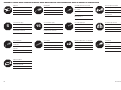
•ASSEMBLY SYMBOL GUIDE•MONTAGE SYMBOLE•GUIDE DES SYMBOLES POUR ASSEMBLAGE•GUIDA AI SIMBOLI DI ASSEMBLAGGIO
5
x2
L
R
L
R
15
OIL
CG
Apply oil
Öl verwenden
Appliquez lubricant
Applicare olio
Use 5-minute epoxy
Verwenden Sie 5 Minuten Epoxy
Utilisez de l’époxy 5 minutes
Usare una resina epossidica con
indurimento di 5 minuti
Use medium CA
Mittelfl üssigen Sekundenkleber
verwenden
Utilisez de la colle cyanoacrylate
moyenne
Usare colla ciano acrilica media
Apply threadlock
Schraubensicherungslack verwenden
Utilisez du frein fi let
Applicare fuido threadlock
Canopy Glue
Kabinenhaubenkleber
Colle à verrière
Colla per capottine
Use 15-minute epoxy
Verwenden Sie 15 Minuten Epoxy
Utilisez de l’époxy 15 minutes
Usare una resina epossidica con
indurimento di 15 minuti
Use a pencil
Verwenden Sie einen Bleistift
Utilisez un crayon à papier
Usare una matita
Use hobby knife with #11 blade
Verwenden Sie ein Hobbymesser mit
# 11 Klinge
Utilisez un Couteau: Lame numéro
11
Usare taglierino per hobbistica con
lama numero 11
Use a felt-tipped pen
Verwenden Sie einen Faserstift
Utilisez un feutre fi n effaçable
Usare un pennarello
Repeat multiple times (as indicated)
Vorgang wiederholen (wie angezeigt)
Répétez comme indiqué
Ripetere più volte (come indicato)
Ensure proper orientation
Ausrichtung/Richtung sicherstellen
Vérifi ez la bonne orientation
Assicurarsi dell’appropriato
orientamento
Assemble right and left
Links und rechts montieren
Assemblez à droite et à gauche
Assemblare destra e sinistra
Use thin CA
Dünnfl üssigen Sekundenkleber
verwenden
Utilisez de la colle cyanoacrylate fi ne
Usare colla ciano acrilica fi ne

11
EFL Habu 32x DF
•FASTENERS•VERBINDUNGSELEMENTE•VISSERIE•ELEMENTI DI FISSAGGIO
M
Threaded rod, threaded both ends
Gewindestangen, zwei Gewinde
Tringlerie fi letée des 2 côtés
Barretta con entrambe estremità fi lettate
Metal Clevis
Gabelkopf
Chape métallique
Forcella metallica
Self-Tapping Screw
Selbstschneidene Schraube
Vis auto-taraudeuse
Vite autofi lettante
Wheel Collar
Stellring
Bague d’arrêt
Collare ruota
Aluminum Spacer
Aludistanzhülse
Entretoise en aluminium
Distanziale alluminio
Hex Nut
Sechskantmutter
Ecrou hexagonal
Dado esagonale
Threaded rod
Gewindestange
Tige fi letée
Barra fi lettata
Self-tapping counter-sunk screw
Selbstschneidene Senkschraube
Vis auto-taraudeuse à tête fraisée
Vite autofi lettante a testa svasata
Socket Head Cap Screw
Inbusschraube
Vis BTR
Vite a brugola
Self-Tapping Washer-Head Screw
Schraube mit Unterlegscheibenkopf
Vis auto-taraudeuse épaulée
Vite autofi lettante fl angiata

12
EFL Habu 32x DF
•BEFORE STARTING ASSEMBLY
• Remove parts from bag.
• Inspect fuselage, wing panels, rudder and stabilizer
for damage.
• If you fi nd damaged or missing parts, contact your
place of purchase.
If you fi nd any wrinkles in the covering, use a heat gun
(HAN100) and covering glove (HAN150) or covering iron
(HAN101) with a sealing iron sock (HAN141) to remove
them. Use caution while working around areas where the
colors overlap to prevent separating the colors.
This model has been designed to keep the weight at a
minimum. When tightening the covering, work carefully
to avoid inducing warps or changing the alignment of the
structure.
• Charge transmitter and receiver batteries.
• Center trims and sticks on your transmitter.
• For a computer radio, create a model memory for this
particular model.
• Bind your transmitter and receiver, using your radio
system’s instructions.
IMPORTANT: Rebind the radio system once all
control throws are set. This will keep the servos from
moving to their endpoints until the transmitter and
receiver connect. It will also guarantee the servo
reversal settings are saved in the radio system.
• During the course of building your model we suggest
you use a soft base for the building surface. Such
things as a foam stand, large piece of bedding foam
or a thick bath towel will work well and help protect
the model from damage during assembly. This is not
shown in the instructions to provide the greatest
detail in the photos.
• When referencing directions (up, down, left, right top
and bottom) these directions are in relationship to the
pilot sitting in the cockpit of the aircraft unless noted
otherwise.
•VOR DEM ZUSAMMENBAU
• Entnehmen Sie zur Überprüfung jedes Teil der
Verpackung.
• Überprüfen Sie den Rumpf, Tragfl ächen, Seiten- und
Höhenruder auf Beschädigung.
• Sollten Sie beschädigte oder fehlende Teile feststellen,
kontaktieren Sie bitte den Verkäufer.
Zum Entfernen von Falten in der Bespannung verwenden
Sie den Heißluftfön (HAN100) und Bespannhandschuh
(HAN150) oder das Folienbügeleisen (HAN141). Bitte
achten Sie bei überlappenden Farben, dass Sie diese sich
bei dem Bearbeitung nicht trennen.
Dieses Modell wurde auf geringstes Gewicht konstruiert.
Bitte beachten Sie bei dem Spannen der Bespannfolie,
dass sie nicht die Ausrichtung der Struktur verändern.
• Laden des Senders und Empfängers.
• Zentrieren der Trimmungen und Sticks auf dem
Sender.
• Sollten Sie einen Computersender verwenden,
resetten Sie einen Speicherplatz und benennen ihn
nach dem Modell.
• Sender und Empfänger jetzt nach den Bindeanweisung
des Herstellers zu binden.
WICHTIG: Wir empfehlen dringend nachdem alle
Einstellungen vorgenommen worden sind, das Modell
neu zu binden. Dieses verhindert, dass die Servos
in die Endanschläge laufen bevor sich Sender und
Empfänger verbunden haben. Es garantiert auch, dass die
Servoreverseeinstellungen in der RC Anlage gesichert sind.
• Wir empfehlen zum Bauen eine geschäumte
Unterlage zu verwenden. Dazu eignet sich ein großer
Schaumständer oder auch ein dickes Handtuch um
das Modell vor Beschädigungen zu schützen. Zur
besseren Sichtbarkeit ist das in der Bauanleitung nicht
abgebildet.
• Bei der Angabe von Richtungen (oben, unten, links,
rechts, Ober- /Unterseite) sind diese Angaben immer
aus der Sicht des im Cockpit sitzenden Piloten gewählt
solange nichts anderes dazu geschrieben wird.
•AVANT DE COMMENCER
L’ASSEMBLAGE
• Retirez toutes les pièces des sachets pour les
inspecter.
• Inspectez soigneusement le fuselage, les ailes et les
empennages.
• Si un élément est endommagé, contactez votre
revendeur.
Si l’entoilage présente des plis, vous pouvez les
lisser en utilisant le pistolet à air chaud (HAN100)
et le gant (HAN150) ou le fer à entoiler (HAN101)
avec la chaussette de protection (HAN141). Agissez
soigneusement dans les zones où plusieurs couleurs
d’entoilage sont superposées afi n d’éviter de les séparer.
Ce modèle a été conçu pour obtenir une masse
minimale. Quand vous retendez l’entoilage, prenez soin
de ne pas déformer la structure.
• ll est recommandé de préparer tous les éléments du
système de la radio.
• Cela inclut, la charge des batteries comme la mise au
neutre des trims et des manches de votre émetteur.
• Si vous utilisez une radio programmable, sélectionnez
une mémoire libre afi n d’y enregistrer les paramètres
de ce modèle.
• Nous vous recommandons d’affecter maintenant le
récepteur à l’émetteur en suivant les instructions
fournies avec votre radio.
IMPORTANT: Il est hautement recommandé de
ré-affecter le système une fois que les courses seront
réglées. Cela empêchera les servos d’aller en butée lors
de la connexion du système. Cela garantit également que
la direction des servos est enregistrée dans l’émetteur.
• . Durant l’assemblage du modèle, nous vous
recommandons de recouvrir votre surface de travail.
En utilisant pas exemple un tapis de stand en mousse,
ou un grand morceau de mousse de rembourrage
ou une serviette de bain épaisse afi n de protéger le
modèle durant l’assemblage. Cet élément n’apparaît
pas dans les instructions de montage afi n de
conserver des informations claires.
• Quand nous parlons d’orientation (Haut, bas, gauche,
droite, dessus et dessous), ces directions utilisent
comme référence la position du pilote dans le cockpit.
•PRIMA DI INIZIARE IL MONTAGGIO
• Togliere tutti i pezzi dalla scatola.
• Verifi care che la fusoliera, l’ala e i piani di coda non
siano danneggiati.
• Se si trovano parti danneggiate, contattare il negozio
da cui è stato acquistato.
Se si trovano delle pieghe nella ricopertura, si possono
togliere usando una pistola ad aria calda (HAN100) e
guanto per ricopertura (HAN150), oppure un ferro per
ricopertura (HAN101) con la sua calza di protezione
(HAN141). Usare cautela quando si lavora in aree del
rivestimento dove ci sono dei colori sovrapposti, per
evitare la loro separazione.
Questo modello è stato progettato per mantenere al
minimo il suo peso. Quando si tende il rivestimento,
bisogna lavorare con attenzione per non fare delle grinze
o modifi care l’allineamento delle strutture (svergolature).
• Caricare il trasmettitore e la batteria di volo.
• Centrare stick e trim sul trasmettitore.
• Con una radio computerizzata creare una nuova
memoria per questo modello.
• Facendo riferimento alle istruzioni del radiocomando,
connettere (bind) trasmettitore e ricevitore.
IMPORTANTE: Ripetere la procedura di connessione
una volta regolate le corse, per evitare che i servi vadano
a fi ne corsa. Garantirà anche che le impostazioni di
inversione del servo vengano salvate nel sistema radio.
• Durante la costruzione del modello, noi suggeriamo di
usare un piano di appoggio morbido come ad esempio
un pezzo di materiale espanso o un asciugamano di
spugna spesso, per proteggere il modello durante il
montaggio. Questo non viene mostrato nelle istruzioni
per avere un maggior dettaglio nelle foto.
• Quando si parla delle direzioni (su, giù, sinistra, destra
in alto e in basso) si fa sempre riferimento al pilota
seduto nell’abitacolo dell’aereo, a meno che sia indicato
diversamente.
Page is loading ...
Page is loading ...

15
EFL Habu 32x DF
1
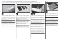
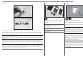
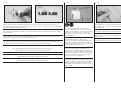
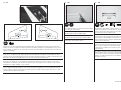
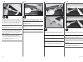
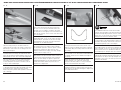
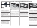
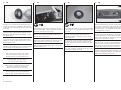
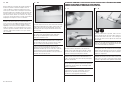
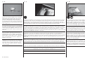
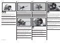
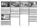
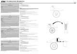
Prepare the aileron servos by installing the rubber grommets and brass eyelets as shown in the radio or servo
instructions. Center the aileron servo using the radio system. Use side cutters to remove any arms from the horn
that may interfere with the operation of the servo. The aileron linkage will be connected to the hole in the servo horn
1/2 inch (13mm) from the center of the arm.
Bereiten Sie das Querruderservo durch einschieben der Gummipuffer und Blechösen vor. Zentrieren Sie das Servo mit
der Fernsteuerung. Entfernen Sie mit dem Seitenschneider alle Arme von dem Servohorn die das Servo im Betrieb
behindern könnten. Die Anlenkung des Querruders wird in das Loch im Servohorn gesteckt das 13mm von der Mitte
entfernt ist.
Préparez les servos des ailerons en y installant les amortisseurs comme indiqué dans le manuel de la radio ou des
servos. Placez le servo au neutre à l’aide la radio. Utilisez une pince coupante pour retirer les partie inutiles du
palonnier qui pourraient interférer avec le fonctionnement du servo. La tringlerie sera connectée au trou du bras de
servo se situant à 13mm du centre.
Preparare i servi degli alettoni installando i gommini e gli occhielli in ottone come viene mostrato nelle istruzioni
della radio o del servo. Centrare il servo degli alettoni usando il radiocomando. Usare un tronchesino per togliere i
bracci non usati dalla squadretta del servo ed evitare che interferiscano con i movimenti. Il rinvio per gli alettoni sarà
collegato al foro che si trova a 13mm dal centro della squadretta del servo.
2
L
R
L
R
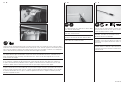
Remove the cover from the wing for the fl ap and
aileron servos. Set the cover aside for the fl ap servo
at this time.
Nehmen Sie bitte die Abdeckungen der Querruder-
und Landeklappenservoschächte ab. Legen Sie die
Abdeckungen zur Seite.
Retirez les trappes de servos de l’aile. Rangez
soigneusement les trappes des servos des volets.
Togliere dall’ala il coperchio per i servi di alettoni e fl ap e
metterlo da parte.
3
L
R
L
R
Use a pencil to draw two lines on the cover. The
fi rst line is along the bottom of the cover, 3/32 inch
(2.5mm) from the edge. The second line is 25/32 inch
(20mm) from the side of the cover as shown. This
will center the servo horn in the slot when using the
recommended servos.
Zeichnen Sie mit einem Stift zwei Linien auf der
Abdeckung. Der erste Linie 2, 5mm über der
Unterkante. Die zweite Linie wie abgebildet 20mm von
der Seite. Diese Markierung zentriert das Servohorn in
der Aussparung. Prüfen Sie dieses zur Sicherheit vorher
mit den von Ihnen verwendeten Servos.
Utilisez un crayon à papier pour tracer 2 ligne sur la
face intérieure de la trappe. La première ligne est
parallèle au bas de la trappe à 2.5mm de distance. La
deuxième ligne sera tracée à 20mm du côté indiqué sur
l’illustration. Ces 2 lignes permettent de centrer le bras
de servo par rapport à la lumière de la trappe quand
vous utilisez les servos recommandés.
Usare una matita per tracciare due linee sul coperchio.
La prima linea è lungo la parte inferiore del coperchio
a 2,5mm dal bordo. La seconda è a 20mm dal lato del
coperchio, come illustrato. Questo serve per centrare
la squadretta del servo nella fessura, quando si usano i
servi consigliati.
•AILERON SERVO INSTALLATION•EINBAU DER QUERRUDERSERVOS•INSTALLATION DES SERVOS D’AILERONS•INSTALLAZIONE SERVO ALETTONI

16
EFL Habu 32x DF
4
x4
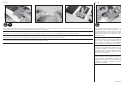
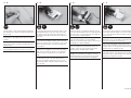
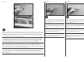
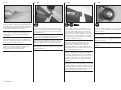
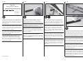
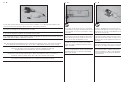
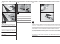
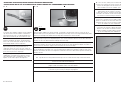
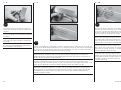
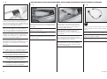
Sand the 10mm x 7mm end of the block using medium
grit sandpaper. This will be the end glued to the plate in
the next step.
Schleifen Sie die 10mm x 7mm Fläche mit mittleren
Schleifpapier an. Der Block wird im nächsten Schritt
verklebt.
Poncez la surface de 10x7mm avec le l’abrasif grain
moyen. Cette surface sera collée à la trappe lors de la
prochaine étape.
Carteggiare un’estremità del blocco da 10 x 7mm che
verrà poi incollato sulla piastra nel passo successivo.
6
L
R
L
R
Position the aileron servo with the grommets resting
on the fi rst mounting block and the servo parallel to the
line on the cover. Use a pencil to mark the location for
the remaining servo mounting block.
Positionieren Sie das Querruderservo mit den
eingesetzten Gummipuffern auf dem Holzblock.
Markieren Sie mit dem Stift die Umrisse des Servos für
die Montage des zweiten Holzblocks.
Positionnez le servo en plaquant ses silent blocs sur
le bloc de fi xation bien à la parallèle de l’arrête de
la trappe. Utilisez un crayon à papier pour repérer
l’emplacement du deuxième bloc de fi xation.
Posizionare il servo alettoni in modo che i gommini
appoggino sul primo blocco di supporto e il servo
sia parallelo alla linea sul coperchio. Con una matita
segnare la posizione dell’altro blocco di supporto.
7
L
R
L
R
5
Use 5-minute epoxy to glue the remaining block to the
cover. Don’t forget to roughen the end of the block.
Use a clamp to hold the block in position until the
epoxy fully cures.
Kleben Sie mit 5 Minuten Epoxy den zweiten Block auf die
Abdeckung. Lassen Sie den Kleber vollständig trocknen
und sichern den Block mit einer Klemme.
Utilisez de la colle Epoxy 5 minutes pour fi xer le
deuxième bloc. N’oubliez pas de poncer la surface à
encoller. Utilisez un serre-joint pour maintenir le bloc en
position durant le séchage de la colle.
Incollare al coperchio anche l’altro blocco usando
colla epoxy 5 minuti, senza dimenticare di irruvidirne
l’estremità. Usare un morsetto per tenere in posizione il
blocco fi nché la colla non è asciutta.
5
L
R
L
R
5
Use 5-minute epoxy to glue the 13mm x 10mm x 7mm
hardwood block to the servo cover. Make sure to glue
the 10mm x 7mm end to the surface of the plate. Use
a clamp to hold the block in position until the epoxy has
fully cured.
Nutzen Sie 5 Minuten Epoxy um den 13mm x 10mm
x 7mm Block an die Klappe zu kleben. Achten Sie bitte
darauf die 10 x 7mm Seite an zu kleben. Lassen Sie den
Kleber vollständig trocknen und sichern den Block mit
einer Klemme.
Utilisez de la colle Epoxy 5 minutes pour coller le bloc
13x10x7mm à la trappe de servo. Prenez soin de bien
coller la face de 10x7mm. Utilisez un serre-joint pour
maintenir le bloc en position durant le séchage de la
colle.
Per incollare il blocco di legno duro da 13 x 10 x 7mm
al coperchio del servo, usare colla epoxy 5 minuti.
Accertarsi di incollare il lato da 10 x 7mm. Usare un
morsetto per tenere in posizione il blocco fi nché la colla
non è asciutta.

17
EFL Habu 32x DF
8
L
R
L
R
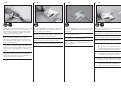
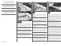
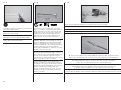
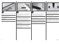
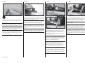
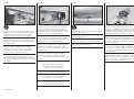
Position the servo between the two blocks. Leave a small
gap between the servo and servo cover so vibrations
from the airframe are not transferred directly into the
servo. Use a pencil to mark the locations for the two
servo mounting screws on the blocks.
Positionieren Sie das Servo zwischen die beiden
Blocks. Lassen Sie einen kleinen Spalt, so dass
Vibrationen des Rumpfes nicht gleich direkt auf das
Servo übertragen werden können. Markieren Sie mit
einem Stift die Bohrlöcher.
Placez le servo entre les 2 blocs. Laissez une petite
distance entre le servo et la trappe afi n de l’isoler des
vibrations de la structure de l’appareil. Utilisez un crayon
pour marquer les emplacements des vis de fi xation sur
les blocs.
Posizionare il servo tra i due blocchi lasciando un piccolo
spazio dal suo coperchio per evitare che le vibrazioni
passino dalla struttura al servo. Usare una matita per
segnare le posizioni delle viti sui blocchi.
9
L
R
L
R
Use a drill and 5/64-inch (2mm) drill bit to drill the holes
for the mounting screws. Use care not to enlarge the
holes any larger than the drill bit.
Bohren Sie mit einem 2mm Bohrer die Löcher für die
Befestigungsschrauben. Bitte achten Sie darauf, dass
die Löcher nicht größer als benötigt werden.
Utilisez un forêt de 2mm pour percer les trous de
fi xation. Prenez soin de ne pas agrandir les trous.
Con una punta da 2mm praticare il foro per le viti di
fi ssaggio. Fare attenzione a non allargare troppo i fori.
10
L
R
L
R
Thread a servo mounting screw into each of the holes in
each of the mounting holes. Remove the screws before
proceeding.
Drehen Sie zum Gewindeschneiden eine Servoschraube in
jedes Loch und wieder hinaus.
Vissez une vis de fi xation de servo dans chacun des
trous. Retirez les vis avant de poursuivre.
Avvitare una vite per il montaggio del servo in ciascuno
dei fori sui blocchi di fi ssaggio del servo. Togliere la vite
prima di procedere.
11
L
R
L
R
Apply a small amount of thin CA to harden the threads
made in the previous step.
Geben Sie einen kleinen Tropfen dünnfl üssigen
Sekundenkleber in die Gewindelöcher um diese zu härten.
Appliquer une petite quantité de colle cyano fi ne pour
durcir les fi letages faits lors de l’étape précédente.
Mettere una piccola quantità di colla CA nei fori, per
indurire il fi letto fatto nel passaggio precedente.
Î Do not use a CA accelerator. Using an
accelerator will not allow the CA to soak into
the fibers of the wood, hardening the blocks.
Î Verwenden Sie bei diesem Arbeitschritt
kein Aktivatorspray, da dieses das durchdringen
des Holzes mit dem Kleber verhindert.
Î N’utilisez pas d’activateur à colle Cyano.
L’utilisation de l’activateur empêcherait la pénétration
de la colle dans les fibres du bois afin de le renforcer.
Î Non usare accelerante CA perché altrimenti
non permetterà alla colla di impregnare il
legno, e quindi di indurirlo adeguatamente.

18
EFL Habu 32x DF
12
L
R
L
R
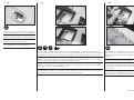
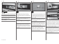
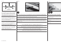
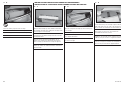
Use the screws provided with the servo and a #1 Phillips
screwdriver to attach the servo to the mounting blocks.
Schrauben Sie das Servo mit den mitgelieferten
Schrauben und einem Phillips #1 Schraubendreher fest.
Utilisez les vis fournies avec le servo et un tournevis
cruciforme #1 pour fi xer le servo aux blocs.
Per fi ssare i servi ai blocchi, usare le viti fornite con
essi, stringendole con un cacciavite Phillips #1.
14
L
R
L
R
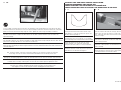
Tie the end of the string located in the aileron servo
opening around the end of the aileron servo lead. Use
the string to pull the aileron servo lead through the
wing panel.
Knoten Sie die Schnur um das Ende des Querruderkabels
und ziehen das Kabel damit durch die Tragfl äche.
Nouez l’extrémité de la fi celle située dans le
compartiment du servo d’aileron autour du câble du
servo. Utilisez la fi celle pour faire glisser la câble au
travers de l’aile.
Legare l’estremità dello spago posizionato nelle aperture
per i servi alettoni ai connettori degli stessi servi. Usare
lo spago per tirare i connettori dei servi attraverso l’ala.
13
L
R
L
R
x4
M2 x 8
x8
Use a #1 Phillips screwdriver to thread an M2 x 8 washer head self-tapping screw into each of the holes for the
servo cover mounting screws. Remove the screws, then apply 2–3 drops of thin CA in each of the aileron servo cover
mounting holes. This will harden the surrounding wood, making the screws more secure when they are installed.
Drehen Sie mit eionem #1 Phillips Schraubendreher eine M2x8 selbstschneidene Schraube in jedes der Löcher.
Drehen Sie die Schraube wieder heraus und geben 2 - 3 Tropfen dünnfl üssigen Sekundenkleber in die Schraublöcher.
Das härtet das umgebende Holz und macht die Schraubverbindung sicherer.
Utilisez un tournevis cruciforme #1 pour visser une vis auto-taraudeuse M2x8 dans chaque trou de fi xation de la
trappe de servo. Retirez les vis, puis appliquez 2 à 3 gouttes de colle cyano fi ne dans chaque trou. Cela permet de
durcir le bois assurant une meilleure fi xation des vis.
Con un cacciavite Phillips #1 avvitare una vite autofi lettante con testa allargata da M2x8 in ciascun foro per il
fi ssaggio del coperchio. Togliere le viti e mettere 2-3 gocce di colla CA in ciascun foro. Questo serve per indurire il
legno circostante e permettere alle viti di fare più presa quando saranno avvitate.

19
EFL Habu 32x DF
Î The opposite end of the string will be
used to pull the flap servo lead through the
wing panel. Use care not to accidentally pull the
wrong end of the string through the wing.
Î Die andere Seite der Schnur wird dazu genutzt
das Kabel des Klappenservos durch die Tragfläche zu
ziehen. Bitte achten Sie darauf nicht aus Versehen das
falsche Ende des Kabels durch die Fläche zu ziehen.
Î L’extrémité opposée de la ficelle sera utilisée
pour tirer le câble du servo de volet à travers l’aile.
Prenez soin de bien tirer sur la ficelle appropriée.
Î L’altro estremo dello spago verrà usato
per tirare i connettori dei servi flap attraverso
l’ala. Attenzione a non tirare attraverso
l’ala l’estremo sbagliato dello spago.
16
x4
Use a hobby knife with a #11 blade to cut 1/4-inch (6mm)
pieces from the silicone tubing.
Schneiden Sie mit einem Hobbymesser mit # 11 Klinge
zwei 6mm lange Stücke vom Silikonschlauch.
Utilisez un couteau de modélisme muni d’une lame #11
pour couper des morceaux de durite silicone de 6mm.
Usare un coltello tagliabalsa con lama #11 per tagliare dei
pezzi da 6mm da un tubetto di silicone.
15
L
R
L
R
M2 x 8
x8
Use four M2 x 8 self-tapping washer-head screws and a #1 Phillips screwdriver to secure the aileron servo cover to
the wing. Make sure the aileron servos are oriented as shown in the drawings.
Schrauben Sie die Servoabdeckung mit den vier 2mm x 8mm Schrauben mit einem # 1 Phillips Schraubendreher fest.
Bitte achten Sie darauf, dass die Querruderservos wie in der Zeichnung abgebildet ausgerichtet sind.
Utilisez 4 vis auto-taraudeuses M2x8mm et un tournevis cruciforme #1 pour fi xer la trappe de servo d’aileron à l’aile.
Suivez les orientations des trappes indiquées sur les schémas.
Per avvitare quattro viti autofi lettanti a testa allargata (con rondella) da M2x8 per fi ssare all’ala il coperchio dei servi
alettoni, usare un cacciavite Phillips #1. Verifi care che i servi siano orientati come illustrato nel disegno.

20
EFL Habu 32x DF
17
x2
x4
M2
x4
M
M2 x 25
x2
Assemble the aileron linkage using the two pieces of
tubing from the previous step, two M2 nuts, two metal
clevises and the M2 x 25 threaded rod. The length of the
rod will be adjusted in the following steps.
Montieren Sie die Querruderanlenkung mit den 2
Schlauchstücken die im Schritt davor gefertigt wurden,
2 mm Muttern, zwei Gabelköpfen und einem 2 mm x
25mm Gewindestück. Die Länge der Anlenkung wird im
nächsten Schritt eingestellt.
Assemblez la tringlerie de l’aileron en utilisant 2
morceaux de durite précédemment coupés, 2 écrous
M2, 2 chapes en métal et une tige fi letée M2x25.
La longueur de la tringlerie sera ajustée lors d’une
prochaine étape.
Assemblare il rinvio per gli alettoni usando due pezzi
di tubetto tagliati nel passaggio precedente, due dadi
M2, due forcelle in metallo e una barretta fi lettata M2
x25mm. La lunghezza dell’insieme verrà regolata nei
passaggi successivi.
18
L
R
L
R
Remove the tape holding the aileron in position. Use the radio system to center the aileron servo. Connect the metal
clevis to the aileron servo arm. The remaining clevis connects to the aileron control horn. Adjust the length of the
linkage so the aileron is centered when the servo is centered. Once the length of the linkage has been adjusted, slide
the tubing over the forks of the clevises to keep them from accidentally opening in fl ight. Use needle nose pliers to
tighten the nuts against the metal clevises.
Entfernen Sie das Klebeband das die Querruder und Landeklappen in Position hält. Zentrieren Sie mit dem Sender
das Querruderservo. Verbinden Sie den Gabelkopf mit dem inneren Loch des Servohornes. Drehen Sie die Länge des
Gestänges so, dass das Ruder und Servo zentriert sind. Schieben Sie dann die Schlauchstücke als Sicherung über die
Gabelköpfe. Kontern Sie mit einer Zange die Muttern gegen die Gabelköpfe.
Retirez l’adhésif de masquage qui maintien l’aileron en position. Utilisez la radio pour placer le servo au neutre.
Connectez la chape métallique au bras du servo. La deuxième chape se connecte au guignol de l’aileron. Réglez la
longueur de la tringlerie de façon que la gouverne soit centrée quand le servo est au neutre. Une fois que la longueur
est ajustée, glissez le morceau de durite sur les fourches des chapes pour éviter leur ouverture accidentelle durant le
vol. Utilisez une pince à becs fi ns pour serrer les écrous contre les chapes métalliques.
Togliere il nastro che teneva gli alettoni in posizione. Usare il radiocomando per centrare i servi. Collegare una
forcella in metallo alla squadretta del servo. L’altra forcella andrà collegata alla squadretta degli alettoni. Regolare
la lunghezza del rinvio in modo che l’alettone sia centrato quando anche il servo è centrato. Una volta regolata la
lunghezza portare i tubetti in silicone sulle forcelle per evitare che si aprano accidentalmente in volo. Usare pinze con
becchi stretti per stringere i dadi contro le forcelle.
•FLAP SERVO INSTALLATION
•EINBAU DER KLAPPENSERVOS
•INSTALLATION DES SERVOS DE
VOLETS
•INSTALLAZIONE DEL SERVO DEI FLAP
Î When centering the flap servo, begin by
setting the throws at the transmitter to 0%
for both the up and down flap positions. This is
done for both 2- and 3-position flap switches.
Î Bei dem Zentrieren der Klappenservos
stellen Sie den Weg senderseitig auf 0%
für die beiden Klappenpositionen ein. Dieses
gilt für 2- und 3-Positionsschalter.
Î Quand vous placez le servo de volet au neutre,
commencez par mettre les courses à 0% à l’émetteur
pour la position haute et la position basse des volets.
C’est valable pour les interrupteurs à 2 et 3 positions.
Î Quando si centra il servo dei flap, bisogna iniziare
a impostare il trasmettitore a 0% per le corse in
alto e in basso dei flap. Questo si deve fare anche
per le posizioni 2 e 3 degli interruttori dei flap.

21
EFL Habu 32x DF
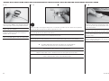
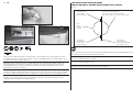
1
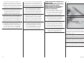
Prepare the fl ap servos by installing the rubber grommets and brass eyelets as shown in the radio or servo
instructions. Center the fl ap servo using the radio system. Use side cutters to remove any arms from the horn that
may interfere with the operation of the servo.
Bereiten Sie das Klappenservo durch einschieben der Gummipuffer und Blechösen vor. Zentrieren Sie das Servo mit
der Fernsteuerung. Entfernen Sie mit dem Seitenschneider alle Arme von dem Servohorn die das Servo im Betrieb
behindern könnten.
Préparez les servos des volets en y installant les amortisseurs comme indiqué dans le manuel de la radio ou des
servos. Placez le servo au neutre à l’aide la radio. Utilisez une pince coupante pour retirer les parties inutiles du
palonnier qui pourraient interférer avec le fonctionnement du servo.
Preparare i servi degli alettoni installando i gommini e gli occhielli in ottone come viene mostrato nelle istruzioni
della radio o del servo. Centrare il servo dei fl ap usando il radiocomando. Usare un tronchesino per togliere dalla
squadretta del servo i bracci non usati ed evitare che interferiscano con i movimenti del servo.
Î The flap linkage will be connected to the hole in the servo horn 1/2 inch
(13mm) from the center of the arm as illustrated in the photo above.
Î Die Klappenanlenkung wird in dem Loch angeschlossen das 13mm von der Mitte entfernt ist. Siehe Abbildung.
Î La tringlerie sera connectée au trou du bras de servo se situant à
13mm du centre. Comme indiqué sur l’illustration ci-dessus.
Î Il rinvio per i flap sarà collegato al foro che si trova a 13mm dal centro
della squadretta del servo, come si vede dalla foto qui sopra.
2
L
R
L
R
Use a pencil to draw two lines on the cover. The
fi rst line is along the bottom of the cover, 3/32 inch
(2.5mm) from the edge. The second line is 25/32 inch
(20mm) from the side of the cover as shown. This
will center the servo horn in the slot when using the
recommended servos.
Zeichnen Sie mit einem Stift zwei Linien auf der
Abdeckung. Der erste Linie 2, 5mm über der
Unterkante. Die zweite Linie wie abgebildet 20mm von
der Seite. Diese Markierung zentriert das Servohorn in
der Aussparung. Prüfen Sie dieses zur Sicherheit vorher
mit den von ihnen verwendeten Servos.
Utilisez un crayon à papier pour tracer 2 ligne sur la
face intérieure de la trappe. La première ligne est
parallèle au bas de la trappe à 2.5mm de distance. La
deuxième ligne sera tracée à 20mm du côté indiqué sur
l’illustration. Ces 2 lignes permettent de centrer le bras
de servo par rapport à la lumière de la trappe quand
vous utilisez les servos recommandés.
Usare una matita per tracciare due linee sul coperchio.
La prima linea è lungo la parte inferiore del coperchio
a 2,5mm dal bordo. La seconda è a 20mm dal lato del
coperchio, come illustrato. Questo serve per centrare
la squadretta del servo nella fessura quando si usano i
servi consigliati.
3
Sand the 10mm x 7mm end of the block using medium
grit sandpaper. This will be the end glued to the plate in
the following step.
Schleifen Sie die 10mm x 7mm Fläche mit mittleren
Schleifpapier an. Der Block wird im nächsten Schritt verklebt.
Poncez la surface de 10x7mm avec l’abrasif grain
moyen. Cette surface sera collée à la trappe lors de la
prochaine étape.
Carteggiare un’estremità del blocco da 10 x 7mm che
verrà poi incollato sulla piastra nel passo successivo.

22
EFL Habu 32x DF
4
L
R
L
R
5
Use 5-minute epoxy to glue the 13mm x 10mm x
7mm hardwood block to the servo cover. Make sure
to glue the 10mm x 7mm end to the surface of the
plate. Use a clamp to hold the block in position until
the epoxy fully cures.
Nutzen Sie 5 Minuten Epoxy um den 13mm x 10mm
x 7mm Block an die Abdeckung zu kleben. Achten Sie
bitte darauf die 10 x 7mm Seite anzukleben. Sichern Sie
den Block mit einer Klemme und lassen Sie den Kleber
vollständig trocknen.
Utilisez de la colle Epoxy 5 minutes pour coller le bloc
13x10x7mm à la trappe de servo. Prenez soin de bien
coller la face de 10x7mm. Utilisez un serre-joint pour
maintenir le bloc en position durant le séchage de la colle.
Per incollare il blocco di legno duro da 13 x 10 x 7mm
al coperchio del servo, usare colla epoxy 5 minuti.
Accertarsi di incollare il lato da 10 x 7mm. Usare un
morsetto per tenere in posizione il blocco fi nché la colla
non è asciutta.
6
L
R
L
R
5
Use 5-minute epoxy to glue the remaining block to the
cover. Don’t forget to roughen the end of the block.
Use a clamp to hold the block in position until the
epoxy fully cures.
Kleben Sie mit 5 Minuten Epoxy den zweiten Block auf
die Abdeckung. Vergessen Sie nicht den Block vorher
anzurauen.Sichern Sie den Block mit einer Klemme und
lassen Sie den Kleber vollständig trocknen.
Utilisez de la colle Epoxy 5 minutes pour fi xer le
deuxième bloc. N’oubliez pas de poncer la surface à
encoller. Utilisez un serre-joint pour maintenir le bloc en
position durant le séchage de la colle.
Incollare al coperchio anche l’altro blocco usando
colla epoxy 5 minuti, senza dimenticare di irruvidirne
l’estremità. Usare un morsetto per tenere in posizione il
blocco fi nché la colla non è asciutta.
7
L
R
L
R
Position the servo between the two blocks. Leave a small
gap between the servo and servo cover so vibrations
from the airframe are not transferred directly into the
servo. Use a pencil to mark the locations for the four
servo mounting screws on the blocks.
Positionieren Sie das Servo zwischen die beiden
Blocks. Lassen Sie einen kleinen Spalt, so dass
Vibrationen des Rumpfes nicht gleich direkt auf das
Servo übertragen werden können. Markieren Sie mit
einem Stift die Bohrlöcher.
Placez le servo entre les 2 blocs. Laissez une petite
distance entre le servo et la trappe afi n de l’isoler
des vibrations de la structure de l’appareil. Utilisez
un crayon pour marquer les emplacements des vis de
fi xation sur les blocs.
Posizionare il servo tra i due blocchi lasciando un
piccolo spazio dal coperchio per evitare che le vibrazioni
passino dalla struttura al servo. Usare una matita per
segnare le posizioni delle quattro viti sui blocchi.
5
L
R
L
R
Position the fl ap servo with the grommets resting on
the fi rst mounting block and the servo parallel to the line
on the cover. Use a pencil to mark the location for the
remaining servo mounting block.
Positionieren Sie das Klappenservo mit den eingesetzten
Gummipuffern auf dem Holzblock. Markieren Sie mit
dem Stift die Umrisse des Servos für die Montage des
zweiten Holzblocks.
Positionnez le servo en plaquant ses silent blocs sur
le bloc de fi xation bien à la parallèle de l’arrête de
la trappe. Utilisez un crayon à papier pour repérer
l’emplacement du deuxième bloc de fi xation.
Posizionare il servo fl ap in modo che i gommini
appoggino sul primo blocco di supporto e il servo sia
parallelo alla linea sul coperchio. Con una matita segnare
la posizione dell’altro blocco di supporto.

23
EFL Habu 32x DF
8
L
R
L
R
Use a drill and 5/64-inch (2mm) drill bit to drill the holes
for the mounting screws. Use care not to enlarge the
holes any larger than the drill bit.
Bohren Sie mit einem 2mm Bohrer die Löcher für die
Befestigungsschrauben. Bitte achten Sie darauf, dass
die Löcher nicht größer als benötigt werden.
Utilisez un forêt de 2mm pour percer les trous de
fi xation. Prenez soin de ne pas agrandir les trous.
Con una punta da 2mm praticare il foro per le viti di
fi ssaggio. Fare attenzione a non allargare troppo i fori.
10
L
R
L
R
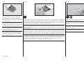
Tie the end of the string around the end of the fl ap servo lead. Use the string to pull the fl ap servo lead through
the wing and out at the root rib as shown.
Knoten Sie die Schnur um das Klappenservokabel. Ziehen Sie mit der Schnur das Kabel aus der Fläche heraus.
Nouez l’extrémité de la fi celle située dans le compartiment du servo de volet autour du câble du servo. Utilisez
la fi celle pour faire glisser la câble au travers de l’aile et le faire sortir à l’emplanture comme sur l’illustration.
Legare l’estremità dello spago posizionato nelle aperture per i servi dei fl ap ai connettori degli stessi servi.
Usare lo spago per tirare i connettori dei servi attraverso l’ala fi no fuori dalla centina che si trova alla radice,
come illustrato.
9
L
R
L
R
Prepare the servo mounting holes by threading the servo
mounting screw into the holes. Remove the screw and
apply a few drops of thin CA in each hole to harden the
surrounding wood. Use the screws provided with the
servo and a #1 Phillips screwdriver to attach the servo
to the mounting blocks.
Bereiten Sie die Montagelöcher durch eindrehen
einer Servoschraube in die Löcher vor. Drehen Sie die
Schraube wieder heraus und geben ein paar Tropfen
dünnfl üssigen Sekundenkleber in die Löcher um das
Holz zu härten. Montieren Sie dann das Servo mit den
Schrauben und einem #1 Phillips Schraubendreher.
Vissez une vis de fi xation de servo dans chacun des
trous. Retirez les vis avant de poursuivre. Appliquer
une petite quantité de colle cyano fi ne pour durcir les
fi letages taillés lors de l’étape précédente. Utilisez les
vis fournies avec le servo et un tournevis cruciforme #1
pour fi xer le servo aux blocs.
Avvitare una vite per il montaggio del servo in ciascuno
dei fori sui blocchi di fi ssaggio del servo. Togliere la
vite e mettere alcune gocce di colla CA in ciascun foro
per indurire il legno circostante. Per fi ssare i servi ai
blocchi, usare le viti fornite con essi, stringendole con un
cacciavite Phillips #1.

24
EFL Habu 32x DF
11
L
R
L
R
M2 x 8
x8
Prepare the servo cover mounting holes by threading the M2 x 8 self-tapping washer-head screw into the holes.
Remove the screws and apply a few drops of thin CA in each hole to harden the surrounding wood. Use the screws
and a #1 Phillips screwdriver to secure the fl ap servo cover to the wing. Make sure the fl ap servos are oriented as
shown in the drawings.
Bereiten Sie die Schraublöcher durch eindrehen einer 2 x 8 selbstschneidenen Schraube vor. Drehen Sie die Schraube
wieder heraus und geben ein paar Tropfen dünnfl üssigen Sekundenkleber in die Löcher um die Gewinde zu härten.
Schrauben Sie die Servoabdeckung mit den vier 2mm x 8mm Schrauben mit einem # 1 Phillips Schraubendreher fest.
Bitte achten Sie darauf, dass die Querruderservos wie in der Zeichnung ausgerichtet sind.
Utilisez un tournevis cruciforme #1 pour visser une vis auto-taraudeuse M2x8 dans chaque trou de fi xation de la
trappe de servo. Retirez les vis, puis appliquez 2 à 3 gouttes de colle cyano fi ne dans chaque trou. Utilisez 4 vis
auto-taraudeuses M2x8mm et un tournevis cruciforme #1 pour fi xer la trappe de servo de volet à l’aile. Suivez les
orientations des trappes indiquées sur les schémas.
Con un cacciavite Phillips #1 avvitare una vite autofi lettante a testa allargata (con rondella) da M2x8 in ciascun foro
per il fi ssaggio del coperchio. Togliere le viti e mettere alcune gocce di colla CA in ciascun foro. Questo serve per
indurire il legno circostante e permettere alle viti di fare più presa quando saranno avvitate. Verifi care che i servi
siano orientati come illustrato nel disegno.
12
x4
Use a hobby knife with a #11 blade to cut 1/4-inch (6mm)
pieces from the silicone tubing.
Schneiden Sie mit einem Hobbymesser mit # 11 Klinge
zwei 6mm lange Stücke vom Silikonschlauch.
Utilisez un couteau de modélisme muni d’une lame #11
pour couper des morceaux de durite silicone de 6mm.
Usare un coltello tagliabalsa con lama #11 per tagliare dei
pezzi da 6mm da un tubetto di silicone.
13
x2
x4
M2
x4
M
M2 x 25
x2
Assemble the aileron linkage using the two pieces of
tubing from the previous step, two M2 nuts, two metal
clevises and the M2 x 25 threaded rod. The length of the
rod will be adjusted in the following steps.
Montieren Sie die Klappenanlenkung mit den 2
Schlauchstücken die im Schritt davor gefertigt wurden,
2 mm Muttern, zwei Gabelköpfen und einem 2 mm x
25mm Gewindestück. Die Länge der Anlenkung wird im
nächsten Schritt eingestellt.
Assemblez la tringlerie de l’aileron en utilisant 2
morceaux de durite précédemment coupés, 2 écrous
M2, 2 chapes en métal et une tige fi letée M2x25.
La longueur de la tringlerie sera ajustée lors d’une
prochaine étape.
Assemblare il rinvio per i fl ap usando due pezzi di
tubetto tagliati nel passo precedente, due dadi M2,
due forcelle in metallo e una barretta fi lettata M2
x25mm. La lunghezza dell’insieme verrà regolata nei
passaggi successivi.

25
EFL Habu 32x DF
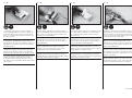
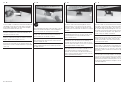
14
L
R
L
R
Remove the tape holding the fl ap in position at the trailing edge of the wing. Use the radio system to center the fl ap
servo. Connect the metal clevis to the outer hole of fl ap servo horn. The remaining clevis connects to the fl ap control
horn. Adjust the length of the linkage so the fl ap is set to the mid/takeoff position. Once the length of the linkage has
been adjusted, slide the tubing over the forks of the clevises to keep them from accidentally opening in fl ight. Use
needle nose pliers to tighten the nuts against the metal clevises.
Entfernen Sie das Kreppband dass die Klappe sichert. Zentrieren Sie mit dem Sender das Klappenservo. Schließen
Sie den Gabelkopf in das äußere Loch des Servohornes an. Den zweiten Gabelkopf schließen Sie am Klappenhebel
am. Stellen Sie die Länge des Gestänges so ein, dass sich die Klappe in mittlerer / Start Position befi ndet. Haben
Sie die Länge eingestellt, schieben Sie bitte die Silikonschlauchstücke als Sicherung über die Gabelköpfe um sie vor
versehentlichen Öffnen zu schützen. Kontern Sie dann mit einer Zange die Muttern gegen die Gabelköpfe.
Retirez l’adhésif de masquage qui maintien le volet en position. Utilisez la radio pour placer le servo au neutre.
Connectez la chape métallique au bras du servo. La deuxième chape se connecte au guignol du volet. Réglez la
longueur de la tringlerie de façon que le volet soit en position milieu/atterrissage. Une fois que la longueur est ajustée,
glissez le morceau de durite sur les fourches des chapes pour éviter leur ouverture accidentelle durant le vol. Utilisez
une pince à becs fi ns pour serrer les écrous contre les chapes métalliques.
Togliere il nastro che teneva i fl ap in posizione. Usare il radiocomando per centrare i servi. Collegare una forcella in
metallo alla squadretta del servo. L’altra forcella andrà collegata alla squadretta dei fl ap. Regolare la lunghezza del
rinvio in modo che il fl ap sia nella posizione centrale di decollo. Una volta regolata la lunghezza portare i tubetti in
silicone sulle forcelle per evitare che si aprano accidentalmente in volo. Usare pinze con becchi stretti per stringere i
dadi contro le forcelle.
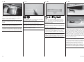
15
L
R
L
R
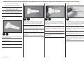
Set the switch at the transmitter to the UP fl ap position.
Adjust the fl ap system values of the transmitter for the up
position until the fl ap is aligned with the aileron. This will
be the UP fl ap position.
Stellen Sie den Schalter am Sender auf die -Klappen
eingefahren- Position. Stellen Sie die Werte am Sender
so ein, dass die Klappe mit dem Querruder auf einer
Linie liegt.
Placez l’interrupteur des volets en position HAUTE.
Effectuez le réglage dans la fonction des volets de votre
émetteur pour aligner les volets par rapport aux ailerons.
Il s’agira de la position HAUTE des volets.
Mettere l’interruttore dei fl ap sul trasmettitore nella
posizione che corrisponde ai fl ap in alto (UP). Regolare il
valore sul trasmettitore in modo il fl ap sia allineato con
l’alettone. Questa è la posizione UP dei fl ap.
16
L
R
L
R
Set the switch at the transmitter to the DOWN fl ap
position. Adjust the ATV at the transmitter for the down
position until the fl ap is 25mm below the aileron. This
will be the DOWN fl ap position.
Stellen Sie den Schalter am Sender auf die -Klappen
ausgefahren- Position. Stellen Sie die ATV (Weg) Werte
am Sender so ein, dass die Klappe 25mm unter dem
Querruder steht.
Placez l’interrupteur des volets de l’émetteur en position
BASSE. Ajuster la valeur de course à l’émetteur de façon
à baisser les volets à 25mm en dessous des ailerons. Il
s’agira de la position basse des volets.
Mettere l’interruttore dei fl ap sul trasmettitore nella
posizione che corrisponde ai fl ap in basso (DOWN).
Regolare l’ATV del trasmettitore fi nché il fl ap non si
trova a 25mm sotto all’alettone. Questa è la posizione
DOWN dei fl ap.
Page is loading ...
Page is loading ...
Page is loading ...
Page is loading ...
Page is loading ...
Page is loading ...
Page is loading ...
Page is loading ...
Page is loading ...
Page is loading ...
Page is loading ...
Page is loading ...
Page is loading ...
Page is loading ...
Page is loading ...
Page is loading ...
Page is loading ...
Page is loading ...
Page is loading ...
Page is loading ...
Page is loading ...
Page is loading ...
Page is loading ...
Page is loading ...
Page is loading ...
Page is loading ...
Page is loading ...
Page is loading ...
Page is loading ...
Page is loading ...
Page is loading ...
Page is loading ...
Page is loading ...
Page is loading ...
Page is loading ...
Page is loading ...
Page is loading ...
Page is loading ...
Page is loading ...
Page is loading ...
Page is loading ...
Page is loading ...
Page is loading ...
Page is loading ...
Page is loading ...
Page is loading ...
Page is loading ...
Page is loading ...
Page is loading ...
Page is loading ...
Page is loading ...
Page is loading ...
Page is loading ...
Page is loading ...
Page is loading ...
Page is loading ...
Page is loading ...
Page is loading ...
Page is loading ...
-
 1
1
-
 2
2
-
 3
3
-
 4
4
-
 5
5
-
 6
6
-
 7
7
-
 8
8
-
 9
9
-
 10
10
-
 11
11
-
 12
12
-
 13
13
-
 14
14
-
 15
15
-
 16
16
-
 17
17
-
 18
18
-
 19
19
-
 20
20
-
 21
21
-
 22
22
-
 23
23
-
 24
24
-
 25
25
-
 26
26
-
 27
27
-
 28
28
-
 29
29
-
 30
30
-
 31
31
-
 32
32
-
 33
33
-
 34
34
-
 35
35
-
 36
36
-
 37
37
-
 38
38
-
 39
39
-
 40
40
-
 41
41
-
 42
42
-
 43
43
-
 44
44
-
 45
45
-
 46
46
-
 47
47
-
 48
48
-
 49
49
-
 50
50
-
 51
51
-
 52
52
-
 53
53
-
 54
54
-
 55
55
-
 56
56
-
 57
57
-
 58
58
-
 59
59
-
 60
60
-
 61
61
-
 62
62
-
 63
63
-
 64
64
-
 65
65
-
 66
66
-
 67
67
-
 68
68
-
 69
69
-
 70
70
-
 71
71
-
 72
72
-
 73
73
-
 74
74
-
 75
75
-
 76
76
-
 77
77
-
 78
78
-
 79
79
-
 80
80
-
 81
81
-
 82
82
-
 83
83
-
 84
84


E-flite Habu 32x DF User manual
- Category
- Remote controlled toys
- Type
- User manual
Ask a question and I''ll find the answer in the document
Finding information in a document is now easier with AI
in other languages
- italiano: E-flite Habu 32x DF Manuale utente
- français: E-flite Habu 32x DF Manuel utilisateur
- Deutsch: E-flite Habu 32x DF Benutzerhandbuch
Related papers
-
E-flite Habu 32 EDF ARF User manual
-
-
-
-
E-flite Mystique EFL4905 User manual
-
-
arf PA-20 Pacer 10e Owner's manual
-
-
E-flite EFLA550 Owner's manual
-
Other documents
-
 Hangar 9 HAN5280 Owner's manual
-
 Hangar 9 HAN2530 Owner's manual
-
 Hangar 9 HAN3390 User manual
-
 Hangar 9 HAN4670 Owner's manual
-
 Hangar 9 HAN6030 Owner's manual
-
ParkZone Habu 2 EDF User manual
-
Horizon Hobby Mystique RES 2.9m ARF User manual
-
 Hangar 9 EFLG630S Owner's manual
-
Ripmax Phase 5 E User manual
-
Black Horse Model Heinkel He 111 User manual


