Page is loading ...

HYDRA-GRIP-O-MATIC
®
PULLER
AND STRAIGHTENER TOOL
Max. Capacity: 6 Ton (PH6 & PH63C); 8 Ton (PH8 & PH83C); 11 Ton (PH11, PH113C, & HST11);
30 Ton (PH30 & PH303C)
NOTE:
• These instructions must be read and carefully followed.
• Carefully inspect the puller and/or straightener tool upon arrival. The carrier, not the manufacturer, is
responsible for any damage resulting from shipment.
SAFETY PRECAUTIONS
WARNING: To help prevent personal injury,
• These pullers and the straightener tool should be used only by trained personnel familiar with them.
• Safety glasses must be worn at all times by the operator and anyone within sight of the puller and
straightener tool.
• Select the proper size and capacity of puller for the job.
• Align the puller on the same centerline as the part being removed. Failure to align parts correctly can
result in a dangerous operating situation because of the high hydraulic pressures used.
• Wrap the work in a Power Team protective blanket before applying pressure to provide protection from
injury caused by flying parts should a part ever break.
• Always apply force gradually.
IMPORTANT: DO NOT USE HEAT, HAMMERS, OR IMPACT TOOLS ON THESE PULLERS.
THIS WILL CAUSE DAMAGE THAT VOIDS THE PULLER WARRANTY.
PULLER SETUP AND OPERATION
NOTE: These pullers have a 2/3-way combination puller
head. The 3-jaw combination is strongly
recommended whenever the job space allows for
it. Three jaws give a more secure grip and more
even pulling force.
1. Select the proper size and capacity of puller needed for the
job. This is determined by measuring "reach" and "spread"
of the part to be pulled.
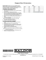
2.
Place the handle assembly into the handle clevis.
See Figure 1.
Form No. 102927
Parts List and
Operating Instructions for:
Sheet No. 1 of 5
Rev 10 Date: 30 Mar 2006
Figure 1
HANDLE
CLEVIS
HANDLE
ASSEMBLY
PH63C
PH83C
PH113C
PH303C
HST11
HST11S
PH6
PH8
PH11
PH30
©
SPX Corporation

Parts List and Operating Instructions, Form No. 102927, Back sheet 1 of 5
PULLER SETUP AND OPERATION (CONTINUED)
3. Turn the control valve knob completely in a clockwise
d
irection to advance the piston. See Figure 2.
IMPORTANT: Position
the control valve knob
so it does not contact
the puller head and can
be turned freely.
4. Begin positioning the puller and puller jaws around the part to be
pulled, removing most of the slack by threading the adjusting
locknut further onto the puller body or adjusting the puller straps
on the jaws. Pump the handle to advance the piston, stopping
just as the removable cone reaches the part. Make final puller
positioning adjustments with the adjusting locknut or the piston.
The puller must be on the same centerline as the part to be
pulled and the jaws fully engaged and secure. See Figure 3.
5. The handle assembly rotates a full 360° to allow
the best handle location for the job. See Figure 4.
Figure 2
Figure 3
Figure 4
CONTROL VALVE
KNOB
REMOVABLE CONE
PULLER PISTON
PART TO BE REMOVED
JAWS FULLY ENGAGED
AND SECURE!
ADJUSTING LOCKNUT
PULLER STRAP
JAW ADJUSTMENT
JAWS
DO NOT USE
PULLER WITH
THE LOCKNUT
ANY LOWER THAN
SHOWN HERE
ADJUSTING
LOCKNUT
PULLER
PISTON
PULLER
BODY
WARNING: The adjusting locknut must be fully
engaged with the threads of the puller
body as shown below on all 6, 8,&11 ton
pullers. On 30 ton puller, full thread
engagement minimum crosshead required.

Parts List and Operating Instructions Form No. 102927
PULLER SETUP AND OPERATION (CONTINUED)
6. Hold the puller with one hand and pump the handle
with your other hand, advancing the piston until the
part is removed. See Figures 5 & 6.
7. Turn the control valve knob completely in a
counterclockwise direction to retract the piston.
See Figure 7.
Sheet No. 2 of 5
Rev 10
Date: 30 Mar 2006
Figure 6
Figure 7
Figure 5
CONTROL VALVE
KNOB

Parts List and Operating Instructions, Form No. 102927, Back sheet 2 of 5
PULLER PARTS LIST
Advance
Return
36

Item Part No. Part No. Part No. No.
No. (For PH63C) (For PH83C) (For PH113C) Req’d Description
Parts List and Operating Instructions Form No. 102927
NOTE: Relief Valve Assembly (Item #34) must not be serviced except by a qualified hydraulic service center.
Contact your nearest service center or Power Team Technical Services for further information.
PREVENTIVE MAINTENANCE
• Keep the puller as clean as possible to help prevent contamination from entering the hydraulic system
and to prevent rust.
• If additional oil is needed, use Power T
eam hydraulic oil or a comparable jack oil.
• Reservoir oil capacity:
• Periodically lubricate puller pivot points.
• Store the puller and all accessories in its plastic case.
Sheet No. 3 of 5
Rev 10 Date: 30 Mar 2006
1 252926 252926 252926 1 Handle Clevis
2
252933 252933 252933 1 Clevis Pin - Long
3
2
52936 252936 252936
1
Handle Lever
4
2
52941 252941 252941
1
Retainer Nut
6 2
52914 252914 252914
1
Pump Housing and Piston
Rod Assembly
7
252912 252912 252912 1 Swivel Clevis
8
252913 252913 252913 1 Inlet/Outlet Valve Assembly
9 252908 252909 252910 1 Bladder Housing
10
252911 252911 252911 1 Bladder Housing Retainer Nut
11
252903 252904 252904 1 Control Valve Knob
12 252902 252902 252902 1 O-ring
13
252925 252925 252925 1 Link Connector
14
252932 252932 252932 3 Retaining Ring
15 252887 252887 252887 1 Compression Ring - Small
16 252905 252906 252907 1 Reservoir Bladder
17
252888 252889 252890 1 Compression Ring - Large
18
252900 252900 252900 1 Oil Fill Screw Assembly
19
252894 252895 252896 1 Hydraulic Puller Body
20 252901 252916 252916 1 Steel Ball
21 252937 252938 252939 1 U-cup
22 252940 252940 252940 1 O-ring
23 252891 252892 252893 1 Puller Piston Rod
24 252917 252918 252919 1 Puller Crosshead
25 252882 252883 252884 1 Cylinder Retaining Nut
26 252934 252934 252935 1 Rod Wiper
27 252885 252886 252886 1 Compression Spring
28 252930 252930 252931 1 Removable Cone Assembly
29
252923 252924 252924 6 Puller Strap
30 252920 252921 252922 3 Puller Jaw
*30902 *30902 3 Long Puller Jaw (Optional)
31 252927 252928 252928 6 Puller Jaw Screw and Nut
32 252897 252898 252899 1 Adjusting Locknut
33 252957 252957 252957 1 Handle Grip Assembly
34 --- --- --- 1 See Note Below
35 252951 252951 252951 2 Clevis Pin - Short
36 PH6 PH8 PH11 1 Replacement Hydraulic
Assembly Complete w/ Handle
PARTS INCLUDED BUT NOT SHOWN
351491 351492 351493 1 Trade Name Decal
252948
252949
252950
1
Plastic Case
*To order a set of three long jaws, order No. 1188.
PH6 & PH63C
=
.19 pt (90 cc)
PH8 & PH83C = .25 pt (120 cc)
PH1
1 & PH1
13C = .32 pt (150 cc)

Parts List and Operating Instructions, Form No. 102927, Back sheet 3 of 5
PULLER PARTS LIST-PH303C
15
1
2
3
(
4)
18
17
1
6
4
5
6
7
8
9
3
(2)
2
10
11
12
13
14
19
20
21
24
25
26
27
29
28
30
22
23
31
32
33
34
35
36
37
38
39
(6)
40
(3)
41
(6)
42
(6)
48

Parts List and Operating Instructions Form No. 102927
PH303C PULLER, HYD. GEAR 30 TON, W CASE & BLANKET
Sheet No. 4 of 5
Rev 10 Date: 30 Mar 2006
ITEM SPX QTY DESCRIPTION
NO. P/N
1 252926 1 Clevis, Handle
2
2000616 2 Pin, Clevis - Short
3
252932 6 Ring, Retaining
4
2000620 1 Pin, Clevis - Long
5
252936 1 Lever, Handle
6
2
52941 1
N
ut, Retainer (Nut, Cylinder Retaining)
7
252957 1 Assembly, Handle Grip
8
252925 1 Link, Connector
9
252914 1 Assembly, Pump Housing Pump and Piston
10
252912 1 Clevis,Swivel
1
1
2
52940 1
O
-ring
12
252913 1 Assembly, Inlet / Outlet Valve
13
2000599 1 Nut, Retainer Housing Bladder
14
2000598 1 Housing,Bladder
15
2000621 1 Screw, Drag Spring
16
252887 1 Ring, Compression - Small (Spring)
17
2000601 1 Bladder, Reservoir
18
2000602 1 Ring, Compression - Large (Spring)
19
252916 1 Ball, Steel .250"
20
252902 1 O-ring
21
2000600 1 Knob, Valve Control
22
2000603 1 Body, Hydraulic Puller
23
2000622 1 Spring, Drag
24
1
25 1
26 1
27 1
28 2
29 1
30 2000629 1 Screw, Ass'y Oil Fill
31
2000604 1 U-cup
32
2000605 1 Rod, Piston Puller
33
2000607 1 Nut, Cylinder Retaining
34
2000608 1 Wiper, Rod Nitrile
35
2000630 2 O-ring
36
2000631 1 Adapter
37
2000632 1 Cone Assembly, Removable
38
2000606 1 Crosshead, Puller
39
2000614 6 Nut, Puller Jaw
40
2000612 3 Jaw, Puller
41
2000611 6 Strap, Puller
42
2000609 6 Screw, Puller Jaw
43
44
2000613 3 Jaw, Long Puller (Optional, Not Shown)
45
2000617 1 Case, Metal Storage
46
2000618 1 Blanket, Protective
47
1000199
1
Decal
48
PH30 1 Pump, Replacement Assembly
NOTE: Relief V
alve Assembly (Item #24–#29) must not be serviced except by a qualified hydraulic service center
.
Contact your nearest service center or Power T
eam Technical Services for further information.
PREVENTIVE MAINTENANCE
• Keep the puller as clean as possible to help prevent contamination from entering the hydraulic system and to
prevent rust.
• If additional oil is needed, use Power Team hydraulic oil or a comparable jack oil.
• Reservoir oil capacity:
• Periodically lubricate puller pivot points.
• Store the puller and all accessories in its plastic case.
PH30 &PH303C = .68 pt (320 cc)

Parts List and Operating Instructions, Form No. 102927, Back sheet 4 of 5
STRAIGHTENER TOOL SETUP AND OPERATION
1
. Thread the straightener tool onto the puller body. See Figure 8.
WARNING: The straightener tool must be fully
engaged with the threads of the
puller body as shown below.
2. Using the indicator marks on the straightener tool
body, position the straightener tool arms an
equal distance apart from the center of the
puller body. See Figure 9.
WARNING: Failure to equally
position the straightener
tool arms on the straightener body
creates a very dangerous situation.
The force will be unevenly distributed
to each arm causing tool breakage
and personal injury.
IMPORT
ANT
: DO NOT USE HEAT,
HAMMERS, OR IMPACT TOOLS ON
THESE PULLERS. THIS WILL CAUSE
DAMAGE THAT VOIDS THE PULLER
WARRANTY.
3. Place the handle assembly into the handle
clevis. See Figure 9.
4. Place puller and tool on a bar or round bar stock
to be straightened. T
urn the control valve knob
completely in a clockwise direction to advance
the piston. See Figure 9.
Figure 8
ALL
THREADS
ENGAGED!
PULLER
PISTON
PULLER
PISTON
CONCAVE SHAFT
ADAPTER SHOULD
BE USED WHEN
STRAIGHTENING
ROUND BAR STOCK
STRAIGHTENER
TOOL BODY
Figure 9
INDICATOR
MARKS
HANDLE
ASSEMBLY
HANDLE CLEVIS
CONTROL VALVE
KNOB
STRAIGHTENER TOOL TO
BE USED ONLY WITH 11
TON PULLER

Parts List and Operating Instructions Form No. 102927
STRAIGHTENER TOOL SETUP AND OPERATION (CONTINUED)
5. Advance the piston by pumping on
the handle until the bar
or round bar stock is straight.
See Figure 10.
6. Turn the control valve knob completely in a
counterclockwise direction to retract the piston.
See Figure 10.
Sheet No. 5 of 5
Rev 10
Date: 30
Mar
2006
Figure 10
CONCAVE
SHAFT ADAPTER
CONTROL VALVE
KNOB

Parts List and Operating Instructions, Form No. 102927, Back sheet 5 of 5
HST11 STRAIGHTENER TOOL
PARTS LIST
Item Part No.
No. No. Req’d Description
5
6
1
2
3
4
7
1 253042 4 Screw
2 253041 2 Strap
3
253037 1 Crossbar
4 253038 2 Jaw Holder
5 253040 4 Nut and Bolt Assembly
6 253039 2
Jaw
7 253060 1 Concave Ram Cap (Assemble to piston rod of puller.)
P
ARTS INCLUDED BUT NOT SHOWN
222142 1 Warning Decal
351563 1
T
rade Name Decal
PH1
1
1
Hydraulic Puller Assembly Complete
(W
ith handle, also see
back sheet 2 of 4 and 3 of 4)
NOTE: HST1
1S is a set consisting of HST1
1 straightener tool and
PH1
1 hydraulic puller with handle.
/