77-2876-R7.6 (9/2017) 1 / 8 www.carlisleft.com
BINKS SV100 CONVENTIONAL
SUCTION FEED SPRAY GUN
The following instructions provide the necessary
information for the proper maintenance of the Binks
SV100 suction feed spray gun. Please read and
understand all the information in this document in
order to get the maximum performance from your
new SV100 suction spray gun.
The SV100 spray gun is the result of quality
engineering and development activity. The result is
an ergonomic product with reduced triggering effort
and fine atomization. The specification table details
the operating parameters of the gun. In addition,
the relatively low air flow rate of the SV100 spray
gun will help in containing overspray.
The SV100 spray gun should be operated under the
safety directions outlined in this literature. Your
safety and the safety of others depend on your
thorough understanding of the material contained
on the Part Sheet.
If you have any questions or do not understand the
content in this literature, call your nearest service
representative.
SPECIFICATIONS
Max. Air Pressure: 175psi/12bar
Gun Body: Cast Aluminum
Fluid Path: Stainless Steel
Fluid Nozzle: Stainless Steel
Fluid Needle: Stainless Steel
Fluid Inlet Size: 3/8" NPS(M)
Air Inlet Size; 1/4" NPS(M)
Gun Weight: 1.17 lbs. (532 g)
SV100-630K @30 psi 8 cfm
Air Consumption: @50 psi 11 cfm
EN
SERVICE MANUAL

77-2876-R7.6 (9/2017)2 / 8
EN
www.carlisleft.com
Binks reserves the right to modify equipment specification without prior notice.
LOCK OUT / TAG-OUT
Failure to de-energize, disconnect, lock out and tag-out all power
sources before performing equipment maintenance could cause
serious injury or death.
OPERATOR TRAINING
All personnel must be trained before operating finishing
equipment.
EQUIPMENT MISUSE HAZARD
Equipment misuse can cause the equipment to rupture,
malfunction, or start unexpectedly and result in serious injury.
PROJECTILE HAZARD
You may be injured by venting liquids or gases that are released
under pressure, or flying debris.
PINCH POINT HAZARD
Moving parts can crush and cut. Pinch points are basically any
areas where there are moving parts.
INSPECT THE EQUIPMENT DAILY
Inspect the equipment for worn or broken parts on a daily basis.
Do not operate the equipment if you are uncertain about its
condition.
In this part sheet, the words WARNING, CAUTION and NOTE are used to
emphasize important safety information as follows:
Hazards or unsafe practices which
could result in minor personal injury,
product or property damage.
!
CAUTION
Hazards or unsafe practices which
could result in severe personal
injury, death or substantial property
damage.
!
WARNING
Important installation, operation or
maintenance information.
NOTE
Read the following warnings before using this equipment.
READ THE MANUAL
Before operating finishing equipment, read and understand all
safety, operation and maintenance information provided in the
operation manual.
WEAR SAFETY GLASSES
Failure to wear safety glasses with side shields could result in
serious eye injury or blindness.
NEVER MODIFY THE EQUIPMENT
Do not modify the equipment unless the manufacturer provides
written approval.
IT IS THE RESPONSIBILITY OF THE EMPLOYER TO PROVIDE THIS INFORMATION TO THE OPERATOR OF THE EQUIPMENT.
FOR FURTHER SAFETY INFORMATION REGARDING THIS EQUIPMENT, SEE THE GENERAL EQUIPMENT SAFETY BOOKLET (77-5300).
KNOW WHERE AND HOW TO SHUT OFF THE EQUIPMENT
IN CASE OF AN EMERGENCY
PRESSURE RELIEF PROCEDURE
Always follow the pressure relief procedure in the equipment
instruction manual.
NOISE HAZARD
You may be injured by loud noise. Hearing protection may be
required when using this equipment.
STATIC CHARGE
Fluid may develop a static charge that must be dissipated through
proper grounding of the equipment, objects to be sprayed and all
other electrically conductive objects in the dispensing area. Improper
grounding or sparks can cause a hazardous condition and result in
fire, explosion or electric shock and other serious injury.
PROP 65 WARNING
WARNING: This product contains chemicals known to the
State of California to cause cancer and birth defects or other
reproductive harm.
WEAR RESPIRATOR
Toxic fumes can cause serious injury or death if inhaled.
Wear a respirator as recommended by the fluid and solvent
manufacturer’s Safety Data Sheet.
TOXIC FLUID & FUMES
Hazardous fluid or toxic fumes can cause serious injury or death if
splashed in the eyes or on the skin, inhaled, injected or
swallowed. LEARN and KNOW the specific hazards or the fluids
you are using.
KEEP EQUIPMENT GUARDS IN PLACE
Do not operate the equipment if the safety devices have been
removed.
!
WARNING
AUTOMATIC EQUIPMENT
Automatic equipment may start suddenly without warning.
FIRE AND EXPLOSION HAZARD
Improper equipment grounding, poor ventilation, open flame or
sparks can cause a hazardous condition and result in fire or
explosion and serious injury.
MEDICAL ALERT
Any injury caused by high pressure liquid can be serious. If you
are injured or even suspect an injury:
• Go to an emergency room immediately.
• Tell the doctor you suspect an injection injury.
• Show the doctor this medical information or the medical alert
card provided with your airless spray equipment.
• Tell the doctor what kind of fluid you were spraying or
dispensing.
GET IMMEDIATE MEDICAL ATTENTION
To prevent contact with the fluid, please note the following:
• Never point the gun/valve at anyone or any part of the body.
• Never put hand or fingers over the spray tip.
• Never attempt to stop or deflect fluid leaks with your hand,
body, glove or rag.
• Always have the tip guard on the spray gun before spraying.
• Always ensure that the gun trigger safety operates before
spraying.

77-2876-R7.6 (9/2017) 3 / 8
EN
www.carlisleft.com
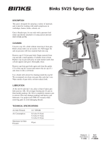
5/16”
1/4”
Only 30 PSI at gun inlet
25 feet of 1/4” I.D. hose causes
a drop of 26 PSI between the air
supply and the gun.
(NOT RECOMMENDED)
50 PSI at gun inlet
25 feet of 5/16” I.D. hose
causes a drop of 12 PSI
between the air supply
and the gun. For this reason
Binks recommends the use
of 5/16” hose.
(RECOMMENDED)
With 60 psi applied at air supply
AIR PRESSURE
Atomizing pressure must be set
properly to allow for the drop in
air pressure between the regula-
tor and the spray gun.
Separator filter is important.
Achieving a fine spray finish without the use of a good separator filter is virtually
impossible.
A Binks regulator / separator filter serves a double purpose. It eliminates blistering
and spotting by keeping air free of oil and water, and it gives precise air pressure
control at the gun.
Binks recommends using Model HFRL-508 Separator Filter / Regulator. See your local
distributor for other models.
Cross section view
showing comparison of inside
hose diameters (actual size).
60 lbs. regulated pressure
OPERATION AND MAINTENANCE FOR SV100 SPRAY GUN
Your new SV100 spray gun is excep-
tionally rugged in construction and is
built to stand up under hard, continuous
use. However, like any other fine preci-
sion instrument, its most efficient oper-
ation depends on a knowledge of its
construction, operation and mainte-
nance. Properly handled and cared for,
it will produce beautiful, uniform finish-
ing results long after other spray guns
have worn out.
SET-UP FOR SPRAYING
Connecting Gun To Air Hose
Air should be supplied by a suitable
length of 5/16" diameter air hose fitted
with a 1/4" NPS(f) connection at gun
end. For hose lengths over 50', use
3/8" diameter hose.
SPRAY GUN CLEANING
INSTRUCTIONS
In certain states it is now against the
law to spray solvents containing Volatile
Organic Compounds (VOC)’s into the
atmosphere when cleaning a spray
gun.
In order to comply with these air quali-
ty laws Binks recommends one of the
following two methods to clean your
spray finishing equipment:
1. Spray solvent through the gun into a
closed system. An enclosed unit or
spray gun cleaning station condens-
es solvent vapors back into liquid
form which prevents escape of
VOC’s into the atmosphere.
2. Place spray gun in a washer type
cleaner. This system must totally
enclose the spray gun, cups, nozzles
and other parts during washing,
rinsing and draining cycles. This
type of unit must be able to flush
solvent through the gun without
releasing any VOC vapors into the
atmosphere.
Additionally, open containers for stor-
age or disposal of solvent or solvent-
containing cloth or paper used for
surface preparation and clean-up may
not be used. All containers shall be
nonabsorbent.
Pointers On Cleaning
When used with 1 quart cup, relieve
pressure in the cup. Then unscrew,
empty and carefully rinse cup out with
thinners. Place clean thinners in the
cup and spray this through the gun
until it is clean. Blow air through gun to
dry it.
All parts on a spray gun should be
screwed in hand tight at first; this
will avoid the possibility of cross
threading the parts. If the parts
cannot be turned by hand easily,
make sure you have the correct parts,
unscrew, realign, and try again.
NEVER use undue force in mating
parts.
!
CAUTION

77-2876-R7.6 (9/2017)4 / 8
EN
www.carlisleft.com
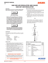
BINKS SV100 CONVENTIONAL SUCTION FEED SPRAY GUN
ITEM PART
NO. NO. DESCRIPTION QTY.
1 SV100-630K AIR CAP ...........................................1
2 ★ — FLUID TIP 1.8 mm w/GASKET ............1
3 ■ — GASKET ............................................1
4 ● — BAFFLE .............................................1
5 ■ ▼ — GASKET ............................................1
6 ★■ ▼ — PACKING w/NUT ...............................1
8 — GUN BODY .......................................1
9 ● — SPRAY PATTERN VALVE .....................1
10■ — U-CUP SEAL ......................................2
11■ — AIR VALVE SEAT ...............................1
12 — AIR VALVE STEM ...............................1
13■ — AIR VALVE SPRING ...........................1
14 — AIR VALVE BUSHING .........................1
15★ — FLUID NEEDLE 1.8 mm ......................1
16★ — FLUID NEEDLE SPRING .....................1
17 — FLUID ADJUSTMENT KNOB ................1
18 — NIPPLE .............................................1
ITEM PART
NO. NO. DESCRIPTION QTY.
19 SGK-457 AIR ADJUSTING VALVE ASSEMBLY .....1
20 — FLUID NIPPLE ...................................1
21 — WASHER ...........................................1
22 — NUT .................................................1
23 — FLUID NIPPLE ASSEMBLY ..................1
24 — TRIGGER PIN ASSEMBLY ...................1
25 — TRIGGER ..........................................1
26■ — ASSEMBLY TOOL ...............................1
27 81-800 1 QT. SIPHON CUP (ALUMINUM) ........1
★ K-5054 Suction Gun Fluid Tip and Needle Replacement Kit
■ K-5057 Soft Parts Kit
▼ SGK-537-K Packing and Baffle Gasket (5 ea.)
● SGK-454-K Spray Pattern Valve and Baffle
PARTS LIST
(When ordering, please specify Part No.)
27

77-2876-R7.6 (9/2017) 5 / 8
EN
www.carlisleft.com
SPRAY TECHNIQUE
The first requirement for a good resultant
finish is the proper handling of the gun.
The gun should be held perpendicular to
the surface being covered and moved
parallel with it. The stroke should be
started before the trigger is pulled and
the trigger should be released before the
stroke is ended. This gives accurate con-
trol of the gun and fluid.
The distance between gun and surface
should be 8 to 10 inches depending on
fluid and atomizing pressure. The fluid
deposited should always be even and
wet. Lap each stroke over the preceding
stroke to obtain a uniform finish. Use
50% overlap.
GENERAL SPRAY
INSTRUCTIONS
To reduce overspray and obtain maximum
efficiency, always spray with the lowest
possible fluid/air pressure that produces
an acceptable spray pattern.
Excessive atomizing air pressures can
increase overspray, reduce transfer effi-
ciency, and with some materials, result in
poor finish quality from dry spray.
For best results, use 3 to 6 psi fluid pres-
sure. Higher than 6 psi fluid pressure
may be required for heavy-bodied materi-
als. Low fluid pressures will produce a
narrower than normal spray pattern.
Generally use 30-35 psi air at gun inlet.
Unusually heavy, difficult to atomize fluids
may require up to 50 psi air at gun inlet.
CONTROLLING THE FAN SPRAY
The fan spray is controlled by means of
the spray pattern valve. Turning this con-
trol clockwise until it is closed will give a
round spray; turning it counterclockwise
will widen the spray into a fan shape.
The fan spray can be turned anywhere
through 360 ° by positioning the air noz-
zle relative to the gun. To accomplish
this, loosen retaining ring, position noz-
zle, then tighten retaining ring.
AIR NOZZLE, FLUID NOZZLE,
FLUID NEEDLE
1. All nozzles and needles are precision
made. They should be handled with
care.
2. Do not make any alterations in the
gun. To do so could cause finishing
difficulties.
3. To clean nozzles, soak them in sol-
vent to dissolve any dried material,
then blow them clean with air.
4. Do not probe any of the holes in the
nozzles with metal instruments.
If probing is necessary, use only a
tool that is softer than brass.
TROUBLESHOOTING
Faulty Spray
A faulty spray pattern is often caused by
improper cleaning resulting in dried mate-
rials around the fluid nozzle tip or in the
air nozzle. Soak these parts in thinners to
soften the dried material and remove with
a brush or cloth.
If either the air nozzle or fluid nozzle are
damaged, these parts must be replaced
before perfect spray can be obtained.
Intermittent Spray
If the spray flutters, it is caused by one
of the following faults:
1. Insufficient fluids available. Check sup-
ply and replenish if necessary.
2. Fluid tip not tightened sufficiently.
3. Packing loose or worn.
NOTE
To reduce overspray and obtain
maximum efficiency always spray
with the lowest possible atomiz-
ing air pressure.
CAUTION
Never use metal instruments to
clean the air or fluid nozzles.
These parts are carefully machined
and any damage to them will
cause faulty spray.
!
OPERATING THE SV100
SPRAY GUN
BINKS SV100 CONVENTIONAL SUCTION FEED SPRAY GUN

77-2876-R7.6 (9/2017)6 / 8
EN
www.carlisleft.com
NOTES

77-2876-R7.6 (9/2017) 7 / 8
EN
www.carlisleft.com
NOTES

77-2876-R7.6 (9/2017)8 / 8
EN
www.carlisleft.com
WARRANTY POLICY
Binks products are covered by Carlisle Fluid Technologies one year materials and workmanship
limited warranty. The use of any parts or accessories, from a source other than
Carlisle Fluid Technologies, will void all warranties. For specic warranty information please contact
the closest Carlisle Fluid Technologies location listed below.
Binks is part of Carlisle Fluid Technologies, a global leader in innovative nishing technologies.
For technical assistance or to locate an authorized distributor, contact one of our international sales
and customer support locations.
USA/Canada
Tel: 1-888-992-4657
Fax: 1-888-246-5732
United Kingdom
Tel: +44 (0)1202 571 111
Fax: +44 (0)1202 573 488
China
Tel: +8621-3373 0108
Fax: +8621-3373 0308
Mexico
Tel: +52 55 5321 2300
Fax: +52 55 5310 4790
Japan
Tel: +81 45 785 6421
Fax: +81 45 785 6517
Germany
Tel: +49 (0) 6074 403 1
Fax: +49 (0) 6074 403 281
Australia
Tel: +61 (0) 2 8525 7555
Fax: +61 (0) 2 8525 7575
Carlisle Fluid Technologies reserves the right to modify equipment specications without prior notice.
DeVilbiss
®
, Ransburg
®
, ms
®
, BGK
®
, and Binks
®
are registered trademarks of Carlisle Fluid Technologies, Inc.
©2017 Carlisle Fluid Technologies, Inc.
All rights reserved.
For the latest information about our products, visit www.carlisleft.com.
/