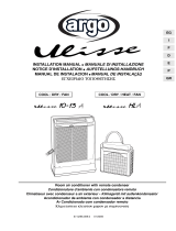
Argo ULISSE ECO Installation guide

Category
Split-system air conditioners
Type
Installation guide

Argo ULISSE ECO is a versatile air conditioner that offers efficient cooling and heating solutions for both residential and commercial spaces. With its advanced features, it ensures optimal temperature control, energy efficiency, and user convenience. Experience a comfortable indoor environment all year round with Argo ULISSE ECO.

Argo ULISSE ECO is a versatile air conditioner that offers efficient cooling and heating solutions for both residential and commercial spaces. With its advanced features, it ensures optimal temperature control, energy efficiency, and user convenience. Experience a comfortable indoor environment all year round with Argo ULISSE ECO.

37.4256.043.00 01/2021
Room air conditioner with remote condenser
Condizionatore d’ambiente con condensatore remoto
Climatiseur avec condenseur a air exterieur - Klimagerät mit außengerät
Acondicionador de ambiente con condensador a distancia
Ar Condicionado com condensador remoto
EN
IT
INSTALLATION MANUAL
MANUALE DI INSTALLAZIONE
NOTICE D’INSTALLATION
INSTALLATIONSANLEITUNG
INSTRUCCIONES DE INSTALACIÓN
INSTRUCÇÕES DE INSTALAÇÃO
FR
DE
ES
PT
35*+
9+:
:[XHU
+IU
4OMNZ
,ORZKX :OSKX 2OMNZ
S
1
MW
TTFS
AUTO
WEEK
SET
23
A
EN
2
CONTENTS
1 - General precaution . . . . . . . . . . . . . . . . . . . . . . . . . . . . . . . . . . . . .3
2 - Installation site selection. . . . . . . . . . . . . . . . . . . . . . . . . . . . . . . . .3
3 - Accessories and tools required for installation . . . . . . . . . . . . . . .3
4 - Dimensions and weight . . . . . . . . . . . . . . . . . . . . . . . . . . . . . . . . .4
5 - Minimum operation and maintenance area . . . . . . . . . . . . . . . . . .4
6 - Tubing length and elevation difference limits . . . . . . . . . . . . . . . . .4
7 - Installation of outdoor unit . . . . . . . . . . . . . . . . . . . . . . . . . . . . . . .5
8 - Wall installation (through a hole in the wall) . . . . . . . . . . . . . . . . . .7
9 - How to connect the  exible tube extension kit . . . . . . . . . . . . . . .9
10 - Remote control unit installation . . . . . . . . . . . . . . . . . . . . . . . . . .10
11 - Maintenance of the refrigerant circuit. . . . . . . . . . . . . . . . . . . . . .10
12 - Match between remote controller and the unit . . . . . . . . . . . . . .11
13 - Electrical wiring diagrams . . . . . . . . . . . . . . . . . . . . . . . . . . . . . . .12
REGULATION (EU) No. 517/2014 - F-GAS
The unit contains R32, ua fluorinated greenhouse gas
with a global warming potential (GWP) of 675. Do not
release R32 into the atmosphere.
R32 (STANDARD): 0.750 kg / 0.506 Tonn. CO2 eq.
R32 (STANDARD + 2 m): 0.785 kg / 0.530 Tonn. CO2 eq.
R32 (STANDARD + 4 m): 0.820 kg / 0.554 Tonn. CO2 eq.
Power supply:
220 - 240 V ~ / 1 / 50 Hz
The unit contains R32, a slightly flammable gas.
Do not try to accelerate the defrosting process or to clean the appliance in different ways other than
those recommended by the manufacturer.
The unit has to be stored in a room that doesn’t have any continuously operating ignition sources (for
example: open flames, an operating gas appliance or an operating electric heater).
Do not pierce or burn the unit.
Be aware that refrigerants do not have any odour.
This unit has to be installed, operated and stored in a room with a floor area larger than 6m2. The room
must be well ventilated.
IN CASE OF MAINTENANCE OF THE REFRIGERANT CIRCUIT
The installer must be in possession of the F-GAS certification without any integration.
The installer must have the appropriate equipment (vacuum pump and recuperator) certified for R32.
Before installing the unit, read this installation manual and streactly follow all safety instructions.
Always contact an Argoclima Service Center.
Any repair must be performed by qualified personnel, following the instructions contained in the
manufacturer’s technical manual.
IMPORTANT
EN
3
1 - GENERAL PRECAUTION
Check that the voltage and frequency of the power supply match those required by the system.
Check the possibility to have the power line to the indoor unit (ELECTRIC CABLE LENGTH 3 m).
Install a double - pole switch, protected by 10 A fuses of the delayed type, upstream the electricity wall socket.
Make sure that the electrical installation is suitable to supply continuosly current necessary for the air conditioner in
addition to that already used by other electric appliances (white goods, lighting). See the max electric imput indica-
ted on the name plate positioned on the air conditioner.
Before connecting the air conditioner to a power socket, make sure that the socket is provided with an earth
connection in compliance with local codes.
2 - INSTALLATION SITE SELECTION
INDOOR UNIT
AVOID:
• Positioning the indoor unit into rooms where it could be sprinkled with water (i.e. laundries).
• Installation in areas where leakage of flammable gas or large amount of mist may be expected humidity location.
• Direct sunlight or near by heat source that may affect performance of the unit.
• Installing the unit behind curtains or furniture that obstruct air circulation.
DO:
Choose a position which allows proper ventilation in the room.
Verify respect of the minimum recommended maintenance space.
OUTDOOR UNIT
AVOID:
Direct sunlight or area where hot air from exhaust fans investing the unit.
DO:
Choose a place as cool as possible and well ventilated.
• Synthetic oil HAB - Alkylbenzene type ex. EXXON ZERICE S, about 30 gr.
• PVC pipe to insulate hole in the wall, external diameter 50 mm. of minimum length as for thickness wall.
• Phillips head screw driver • Tape measure • Level • Hammer drill • Hole saw or key hole saw ø 50
• 19 mm wrench • 21 mm wrench • 24 mm wrench • Hammer • Hacksaw • Core bits 10 mm diameter drill bit.
TOOLS REQUIRED FOR INSTALLATION (NOT SUPPLIED)
ADDITIONAL MATERIAL REQUIRED FOR INSTALLATION (NOT SUPPLIED)
3 - ACCESSORIES AND TOOLS REQUIRED FOR INSTALLATION
THE EXTENSION KITS ARE SUPPLIED PRECHARGED
NARROW TUBE LARGE TUBE
OUTSIDE DIA.
OUTSIDE DIA.
6,35 mm 7,93 mm
Before the installation, verify that they are fit for the unit.
CONNECTION EXTENSION KITS -
LENGHT OF 2 OR 4 m
ACCESSORY SUPPLIED ON REQUEST
FIGURE
PARTS NR°
EXTENSION KIT
FOR CONNEC- 1
TION TUBE
CONNECTIONS 1
PLASTIC BOX
RAWL PLUG 3
TAPPING SCREW 3
ø 3,5 x 45
CLAMP 2
OUTDOOR UNIT SUPPORT
BRACKET KIT
RAWL PLUG 3
S X 10
SCREW 7x65 3
WASHER 3
OUTDOOR UNIT
SUPPORT AND 1+1
GUIDE
SCREW 4,2x13 2
ACCESSORY SUPPLIED ON REQUEST
ACCESSORIES
SUPPLIED WITH THE UNIT
FIGURE
PARTS NR°
REMOTE
UNIT CONTROL 1
BATTERIES FOR
REMOTE CONTROL
2
PLASTIC PLUG
(MALE AND 2 + 2
FEMALE)
FELT PADS 4
SUPPORTS FOR
REMOTE UNIT 2
CONTROL
35*+
9+:
:[XHU
+IU
4OMNZ
,ORZKX :OSKX 2OMNZ
S
1
MW
TTFS
AUTO
WEEK
SET
23
A
EN
4
100 mm
2000 mm
1400 mm
100 mm
780 mm
A
1500 max
A
A
B
clst
800 mm
200 mm
150 mm 150 mm 50 mm
4 - DIMENSIONS AND WEIGHT
800
580
245
525
490
250
Unit: mm
Net weight: 57 Kg
5 - MINIMUM OPERATION AND MAINTENANCE AREA
6 - TUBING LENGTH AND ELEVATION DIFFERENCE LIMITS
Standard mm
2 m system extension kit
4 m system extension kit
A A A
1500 3500 5500
EN
5
Support
Min. 25 cm.
140
3 x ø 10
Holes
100 min.
200
7 - INSTALLATION OF OUTDOOR UNIT
AThe outdoor unit may be placed on a balcony.
Make sure to put it in vertical position and lev-
elled. During the installation do not kink the con-
nection tube between the units. Verify the correct
air circulation around the outdoor unit.
BOr fixed to the window sill.
COr hanged to the wall below the window sill using
the support bracket kit (not supplied). After plac-
ing the unit in the support, check that it is levelled.
Insert the support in the handle of the outdoor
unit, turn the outdoor unit upside down (see the
picture).
Place the support and secure it at the edge of the
unit. Insert the support guide fixed on the unit at
the wall. Make sure it is levelled.
D
EN
6
NO
EDo not handle the outdoor unit improperly. FWhen recovering the outdoor unit after operation
drain away any remaining condensate by tilting
the unit.
GPlace the indoor unit against the wall next to an
electric socket.
TESTOFF ON
EN
7
8 - WALL INSTALLATION (THROUGH A HOLE IN THE WALL)
OPERATION TO BE EXECUTED BY COMPETENT OR QUALIFIED PERSONEL
1. Before disassembling the outdoor unit (disjoin the rapid couplings): connect the air conditioner to a socket and let
the compressor work for 5 minutes. During the disassembling operation, beat lightly with a spanner on the rapid
coupling brass body (exagonal part).
2. Lubricate the joint surfaces (rapid coupling) with a little bit of HAB oil only (synthetic oil Alkylbenzene type ex.
EXXON ZERICE S ).
3. When you disjoin the outdoor unit, follow the described succession: first, disconnect the power supply of the air
conditioner (disconnect the plug), disconnect the electric connector, then the pipes of the frigorific connection.
IMPORTANT
AChoose the best position where to install indoor
unit. Mark the hole to be made in the wall. BDrill a 50 mm diameter hole, insert a PVC pipe.
CRemove the coupling cover of the outdoor unit.
60
50
ø 50
5 - 10 mm
Indoor Outdoor
DDisconnect the condensate plastic tube and the
electric connector.
ELoosen the quick coupling using the 19-21 mm
spanners first and then the 19-24 mm spanners.
Unscrew the flare nuts by hand and disconnect
the flexible tube.
FProtect quick coupling (on flexible tube and out-
door unit) with plastic plugs supplied as accesso-
ries. To insert the tubing into the hole in the wall
easily and without damages, join the pipe ends
and wrap them with adhesive tape.
Plastic plugs
NOTE: When disconnecting or reconnecting the flex-
ible tubes, always use two proper wrenches: one to
hold the fixed part and one to screw/unscrew.
EN
8
HThe unit can be placed on a balcony or hanged
to the wall using the support bracket kit (not sup-
plied).
IDrill the holes and fix the support to the wall using
the rawl plugs. LRemove the plastic plugs from quick couplings,
connect the couplings by hand, then tighten using
the torque wrenches (tightening torque 150 ÷ 165
kgcm).
MConnect the condensate plastic tube and the
electric connector. NFix the coupling cover of the outdoor unit and seal
the hole in the wall around the flexible tube.
GInsert the flexible tube into the hole drilled in the
wall. Place the unit against the wall, if necessary,
adjust the four antivibration supports in order to
keep the unit levelled.
NOTES:
The four antivibration supports are rubber
made and they could mark the floor; in this
case the application of proper material under
the support is recommended or use the sup-
plied felt pads.
TESTOFF ON
When you assemble the outside unit, follow the
described succession: first, connect the pipes
for frigorific connection, then the electric con-
nector.
WARNING
When you move the unit,
never tilt it, to avoid dam-
aging the floor.
EN
9
9 - HOW TO CONNECT THE FLEXIBLE TUBE EXTENSION KIT
OPERATION TO BE EXECUTED BY COMPETENT OR QUALIFIED PERSONEL
IMPORTANT
ACarefully unroll the extension tube; be careful not
to twist nor kink it. BRemove the plastic plug from extension tube ends
(preformed tubes side).
CFit the copper tubes on the support bent side.
Connect the couplings by hand, adjust careful-
ly the tubes on unit top, then tighten using the
torque wrenches (tightening torque 150 ÷ 165
kgcm).
DConnect the condensate plastic tube and the
electric connector.
NO
YES
30 mm
EFix the coupling cover of the outdoor unit. FRemove the plastic plugs from opposite end of
flexible tube and connect quick couplings, first by
hand and then using the spanners.
Cut the PVC tube (soft kind) in excess then insert
it into the stiff one.
NOTE: When disconnecting or reconnecting the flex-
ible tubes, always use two proper wrenches: one to
hold the fixed part and one to screw/unscrew.
NOTE: When disconnecting or reconnecting the flex-
ible tubes, always use two proper wrenches: one to
hold the fixed part and one to screw/unscrew.
EN
10
GH
Open the quick coupling box. Adjust the couplings in the box, connect the elec-
tric cable connector then turn it by 180°. Place
the electric cable and fix it to the pipe with the
smallest diameter through hose clamps. Fix the
gaskets on the connections box ends.
To ensure that the air conditioner operates correctly, DO NOT install the remote control unit in the following places:
In direct sunlight.
Behind a curtain or other places where it is covered.
More than 8 m. away from the air conditioner.
In the path of the air conditioner airstream.
Where it may become extremely hot or cold.
Where it may be subject to electrical or magnetic noise.
Where there is an obstacle between the remote control unit and air conditioner.
WALL-MOUNTED POSITION
Momentarily place the remote control unit in the desired mounting position.
Verify that the remote control unit can operate from this position.
Fix the support at the wall with two screws and hang the remote control unit.
10 - REMOTE CONTROL UNIT INSTALLATION
NOTES
Make sure there is no heat source or potential heat source in the maintenance area. The open flames are forbid-
den in the maintenance area and the “no smoking” sign must be hanged.
Verify that the warning sign is in good condition, otherwise replace it.
Refrigerant recovery in case of maintenance or removal of the unit
If it is necessary to cut and weld the refrigeration circuit pipes during maintenance operations or to empty the
refrigerant circuit in the event of removal of the unit, carry out the following operations:
1. Turn off the unit and disconnect the power supply.
2. Recover the gas.
3. Make a vacuum with the vacuum pump.
4. Clean the pipes with N2 gas.
5. Cut and weld or bring the unit to the Service Center for welding.
6. Make a leak detection check.
The refrigerant must be recovered in the appropriate storage tank for R32 gas.
Ensure that there is no naked flame near the vacuum pump outlet and that the area is well ventilated.
Charge of the refrigeration circuit
Refrigerant charge apparatus, vacuum pump, hoses and adapters must be exclusively used for R32. Make sure
that different types of refrigerant do not contaminate each other.
It is suggested to charge the refrigerant in LIQUID state. Make sure that the refrigerant is the one required.
Do not add any OIL to the compressor because precharged oil is specially selected for R410A.
The refrigerant tank should be kept upright during filling of the refrigerant circuit.
Stick the label on the system after you finish the refrigerant charge.
Do not overfill.
After completing the charge, check for leaks before doing the test run.
IMPORTANT FOR MAINTENANCE
11 - MAINTENANCE OF THE REFRIGERANT CIRCUIT
WALL
SUPPORT
TABLE
STAND
EN
11
The remote control can be addressed to use up to 4 different units installed in the same room.
You can get unified control by using a single remote control for all units or each remote control can be addressed to
its own unit, in order to control separately temperature, timer and all other functions.
12 - MATCH BETWEEN REMOTE CONTROLLER AND THE UNIT
PCB SETTING
Disconnect the unit power supply and wait at least 60 seconds, mak-
ing sure that all the lamps go off.
Remove the rear panel and the cover of the electrical box to access
the pcb.
Set JP2 and JP3 as shown in the table.
Close the cover of the electrical box and the rear panel.
Reconnect the unit power supply.
REMOTE CONTROLLER SETTING
Press the button for a few seconds.
Press the arrow until you visualize 06.
Press the button again for a few seconds: the number 0 (factory
setting) at the bottom starts flashing.
Press the arrow to set 1, 2 or 3.
Confirm with the button .
Press to exit the menu.
35*+
9+:
35*+
9+:
35*+
9+:
0
FACTORY STATE
JP2=CLOSE JP3=CLOSE
1
JP2=OPEN JP3=CLOSE
2
JP2=CLOSE JP3=OPEN
3
JP2=OPEN JP3=APERTO
REMOTE CONTROL UNIT PCB
UNIT
12
13 - ELECTRICAL WIRING DIAGRAMS - SCHEMI ELETTRICI - SCHÉMAS ÉLECTRIQUES - ELEKTRISCHE
ANSCHLUSSPLÄNE - ESQUEMAS ELÉCTRICOS - DIAGRAMAS ELÉTRICOS
WiFI MODELS
13
Wires color legend
Legenda colori fili elettrici
Légende des couleurs des fils électriques
Beschriftung der Leitungs-Farben
Leyenda de los colores de los cable electricos
Legenda das cores dos fios elétricos
E
lectrical wiring diagrams’ symbols / Simboli schemi elettrici / Symboles des schemas électriques
Legende: Anschlusspläne / Símbolos de los esquemas eléctricos / Símbolos de diagramas elétricos
SYMBOL EG I F D E P
PC CONDENSATE PUMP POMPA SCARICO CONDENSA POMPE D’EVACUATION DES CONDENSATS
KONDENSWASSERAUSLASS-PUMPE
BOMBA DE DESCARGA DEL LIQUIDO DE COND.
BOMBA DE DRENAGEM DE CONDENSADO
CM COMPRESSOR MOTOR MOTORE COMPRESSORE MOTEUR DE COMPRESSEUR KOMPRESSORMOTOR MOTOR DEL COMPRESOR MOTOR DO COMPRESSOR
C1, 2, 3 CAPACITOR CONDENSATORE CONDENSATEUR KONDENSATOR CONDENSADOR CAPACITOR
IND. U. INDOOR UNIT UNITA’ INTERNA UNITÉ INTÉRIEURE INNENEINHEITEN UNIDAD INTERIOR UNIDADE INTERNA
OUTD. U. OUTDOOR UNIT UNITA’ ESTERNA UNITÉ EXTÉRIEURE AUßENEINHEITEN UNIDAD EXTERIOR UNIDADE EXTERNA
FMO OUTDOOR FAN MOTOR MOTORE ESTERNO VENTOLA MOTEUR DE VENTILATEUR EXTÉRIEUR AUSSENLÜFTERMOTOR MOTOR VENTILADOR EXTERNO MOTOR VENTILADOR EXTERNO
FMI INDOOR FAN MOTOR MOTORE INTERNO VENTOLA MOTEUR DE VENTILATEUR INTÉRIEUR INNENLÜFTERMOTOR MOTOR VENTILADOR INTERNO MOTOR VENTILADOR INTERNO
IND. ASSY INDICATOR ASSY GRUPPO INDICATORI ENSEMBLE INDICATEUR ANZEIGE-BAUGRUPPE GRUPPO DE INDICADORES GRUPO INDICADORES
A1 CONTROLLER SCHEDA ELETTRONICA CONTRÔLEUR STEUERGERÄT CONTROLADOR PLACA ELETRÔNICA
FS SAFETY FLOAT SWITCH INT. SICUREZZA A GALL. INTERR. DE SECURITE A FLOTTEUR SCHWEMM-SCHUTZSCHALTER
INTERR. DE SEGURIDAD DE FLOTADOR
INTERRUPTOR DE SEGURANÇA EM FLOAT
A2 SWITCH ASSY GRUPPO INTERRUTTORI ENSEMBLE INTERRUPTEUR SCHALTER-BAUGRUPPE GRUPPO DE INTERRUPTORES GRUPO INTERRUPTORES
TH1, 2 THERMISTOR TERMISTORE THERMISTOR THERMISTOR TERMISTOR TERMISTOR
INDUCTOR INDUCTOR INDUTTORE INDUCTOR INDUCTOR INDUCTOR INDUCTOR
EMI FILTER EMI FILTER FILTRO DI RETE FILTRE DE RESEAU NETZFILTER FILTRO DE RED FILTRO DE REDE
EG I F D E P
BLK BLACK NERO NOIR SCHWARZ NEGRO PRETO
BLU BLUE BLU BLEU BLAU AZUL AZUL
BRN BROWN MARRONE MARRON BRAUN MARRON MARROM
GRN / YEL GREEN / YELLOW VERDE / GIALLO VERT / JAUNE GRÜN / GELB VERDE / AMARILLO VERDE / AMARELO
GRY GREY GRIGIO GRIS GRAU GRIS CINZA
ORG ORANGE ARANCIONE ORANGE ORANGE ANARANJADO LARANJA
PNK PINK ROSA ROSE ROSA ROSA ROSA
RED RED ROSSO ROUGE ROT ROJO VERMELHO
VLT VIOLET VIOLA VIOLET VIOLETT VIOLETA VIOLETA
WHT WHITE BIANCO BLANC WEISS BLANCO BRANCO
YEL YELLOW GIALLO JAUNE GELB AMARILLO AMARELO
S.A.C. - Printed in italy
Via Alfeno Varo, 35 - 25020 Alfianello - BS - Italy
Tel. +39 0331 755111 - Fax +39 0331 755501
www.argoclima.com
  • Page 1 1
  • Page 2 2
  • Page 3 3
  • Page 4 4
  • Page 5 5
  • Page 6 6
  • Page 7 7
  • Page 8 8
  • Page 9 9
  • Page 10 10
  • Page 11 11
  • Page 12 12
  • Page 13 13
  • Page 14 14

Argo ULISSE ECO Installation guide

Category
Split-system air conditioners
Type
Installation guide

Argo ULISSE ECO is a versatile air conditioner that offers efficient cooling and heating solutions for both residential and commercial spaces. With its advanced features, it ensures optimal temperature control, energy efficiency, and user convenience. Experience a comfortable indoor environment all year round with Argo ULISSE ECO.

Ask a question and I''ll find the answer in the document

Finding information in a document is now easier with AI