Rice Lake Summit SD-1150-WP is a heavy-duty wheelchair scale designed for use in medical facilities. It has a large 36" x 36" platform and can weigh up to 1000 lbs. The scale features a digital display that shows weight in pounds or kilograms, and it can be used to calculate BMI. It also has a hold/release function and a tare function. The SD-1150-WP is easy to use and can be installed in a pit flush with the floor.
Rice Lake Summit SD-1150-WP is a heavy-duty wheelchair scale designed for use in medical facilities. It has a large 36" x 36" platform and can weigh up to 1000 lbs. The scale features a digital display that shows weight in pounds or kilograms, and it can be used to calculate BMI. It also has a hold/release function and a tare function. The SD-1150-WP is easy to use and can be installed in a pit flush with the floor.


-
 1
1
-
 2
2
-
 3
3
-
 4
4
-
 5
5
-
 6
6
-
 7
7
-
 8
8
-
 9
9
-
 10
10
-
 11
11
-
 12
12
-
 13
13
-
 14
14
-
 15
15
-
 16
16
-
 17
17
-
 18
18
-
 19
19
-
 20
20
-
 21
21
-
 22
22


Rice Lake Summit SD-1150-WP is a heavy-duty wheelchair scale designed for use in medical facilities. It has a large 36" x 36" platform and can weigh up to 1000 lbs. The scale features a digital display that shows weight in pounds or kilograms, and it can be used to calculate BMI. It also has a hold/release function and a tare function. The SD-1150-WP is easy to use and can be installed in a pit flush with the floor.
Ask a question and I''ll find the answer in the document
Finding information in a document is now easier with AI
Related papers
-
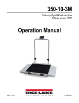
 Rice Lake 350-10-3M User manual
-
 Rice Lake 350-10-3M User manual
-
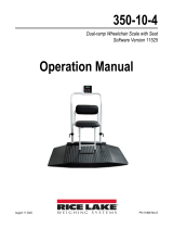 Rice Lake 350-10-4 User manual
-
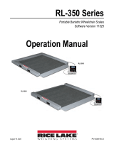 Rice Lake RL-350 Series User manual
-
Rice Lake 350-10-8S User manual
-
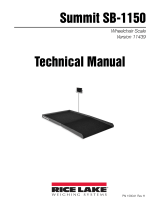 Rice Lake SB-1150 User manual
-
Rice Lake 560-10-1 User manual
-
-
Rice Lake 250-10-4 User manual
-
Rice Lake 160-10-7N User manual


Other documents
-
Summit SB-1150SB-1150 Bariatric Wheelchair Scale User manual
-
Detecto Solace In-Floor Dialysis Scale Owner's manual
-
-
-
Cardinal Detecto 6735 Owner's manual
-
-
-
-
-