Page is loading ...

Section 300
Installation
Panasonic
a
(Applies to CPC-AII/B Version 9.2
and CPC-EX Version 2.3)
Version 2.3/9.2
Revised April 2000

The contents of this manual are subject to change without notice and do not constitute a
commitment on the part of Panasonic Telecommunication Systems Company (PTSC). Every
effort has been made to ensure the accuracy of this document. However, due to ongoing product
improvements and revisions, Panasonic cannot guarantee the accuracy of printed material after
the date of publication nor can it accept responsibility for errors or omissions. Panasonic will
update and revise this document as needed.
This document may be reproduced either electronically or in print as needed by certified dealers
and technicians of DBS products. However, the information contained in this document must not
be altered, copied, or changed in any way that misrepresents the installation, operation, or other
function or feature of the DBS product or Panasonic. Panasonic assumes no liability for any
alteration or misrepresentation of information contained herein.
The software and hardware described in this document may be used or copied only in accordance
with the terms of the license pertaining to said software or hardware.
Copyright 1995 by Panasonic Telecommunication Systems Company
Revised April 2000
All rights reserved.
Warning:
This service information is designed for experienced repair
technicians only and is not designed for use by the general public. It does not
contain warnings or cautions to advise non-technical individuals of potential
dangers in attempting to service a product. Products powered by electricity
should be serviced or repaired only by experienced professional technicians.
Any attempt to service or repair the product or products dealt with in this
service information by anyone else could result in serious injury or death.

DBS-2.3/9.2-300 DBS Manual - Revised April 2000 iii
Table of Contents
Purpose ...................................................................................................................................... xi
Related Documents ................................................................................................................... xi
Chapter 1 Requirements .......................................... 1-1
Model Numbers ...................................................................................................................... 1-1
FCC Requirements .................................................................................................................. 1-1
General Requirements ............................................................................................................. 1-1
DID Requirements ..................................................................................................................1-3
T1 Requirements .....................................................................................................................1-4
Environmental Requirements .................................................................................................1-4
Cleaning ..................................................................................................................................1-5
Chapter 2 System Overview .................................... 2-1
Cabinet Description ................................................................................................................ 2-3
Configurations ........................................................................................................................2-5
Printed Circuit Cards ..............................................................................................................2-6
Processor Description .............................................................................................................2-9
Chapter 3 Cabinet Installation ................................. 3-1
Wall-Mounting the Cabinet .................................................................................................... 3-3
Guidelines ...............................................................................................................................3-3
Installation ..............................................................................................................................3-3
Grounding ...............................................................................................................................3-5
Guidelines ...............................................................................................................................3-5
Installation ..............................................................................................................................3-5
Card Installation ......................................................................................................................3-6
Guidelines ...............................................................................................................................3-6
Installation ..............................................................................................................................3-8
Battery Backup .......................................................................................................................3-9
Guidelines ...............................................................................................................................3-9
Installation for the DBS 40 ................................................................................................... 3-10
Installation for the DBS 72 and 96 ....................................................................................... 3-11
Key Phone Wall Mounting ................................................................................................... 3-13
DSLT Wall Mounting ...........................................................................................................3-15
System Initialization ............................................................................................................. 3-17
Test Phone ............................................................................................................................. 3-18
Guidelines .............................................................................................................................3-18
Installation ............................................................................................................................3-18

Contents Section 300-Installation
iv DBS Manual - Revised April 2000 DBS-2.3/9.2-300
Chapter 4 Trunks and Lines .................................... 4-1
Trunks .....................................................................................................................................4-3
Trunk Connectors ................................................................................................................... 4-3
Trunk Connector Pinouts ........................................................................................................4-4
Loop-Start Trunks ................................................................................................................... 4-7
Ground Start and DID Trunks ................................................................................................ 4-9
T1 Interface ........................................................................................................................... 4-11
Lines ......................................................................................................................................4-31
Extension Connectors ...........................................................................................................4-31
Extension Connector Pinouts ................................................................................................ 4-32
Analog Extensions ................................................................................................................ 4-37
Digital Extensions ................................................................................................................. 4-41
Trunk and Line Expansion ....................................................................................................4-44
Chapter 5 Peripheral Equipment ............................. 5-1
Local Terminal or SMDR Device ........................................................................................... 5-3
Guidelines ...............................................................................................................................5-3
Installation ..............................................................................................................................5-4
Remote Administration Interface (RAI) ................................................................................. 5-6
Guidelines ...............................................................................................................................5-6
Installation ..............................................................................................................................5-6
Background Music/Music-On-Hold .......................................................................................5-8
Guidelines ...............................................................................................................................5-8
Installation ..............................................................................................................................5-8
Off-Premises Adaptor (OPX) ............................................................................................... 5-10
Guidelines .............................................................................................................................5-10
Installation ............................................................................................................................5-11
Paging ...................................................................................................................................5-14
Guidelines .............................................................................................................................5-14
External Page Zone Installation ............................................................................................ 5-14
External General Page/UNA Installation .............................................................................. 5-16
External Ringer (UNA Device) ............................................................................................ 5-17
Guidelines .............................................................................................................................5-17
Installation ............................................................................................................................5-18
Power Failure Unit ................................................................................................................ 5-19
Guidelines .............................................................................................................................5-19
Installation ............................................................................................................................5-19
Voice Announce Unit (VAU) ............................................................................................... 5-22
Guidelines .............................................................................................................................5-22
Installation ............................................................................................................................5-22
Recording and Playing Messages .........................................................................................5-26
Door Box Adaptor (Trunk Port) ...........................................................................................5-27
Guidelines .............................................................................................................................5-27

Section 300-Installation Contents
DBS-2.3/9.2-300 DBS Manual - Revised April 2000 v
Installation ............................................................................................................................5-28
Door Box Adaptor (Extension Port) .....................................................................................5-31
Single Line Telephone Adaptor ............................................................................................ 5-34
Chapter 6 Double-Cabinet Systems ....................... 6-1
Guidelines ...............................................................................................................................6-3
Installation ............................................................................................................................6-10
Chapter 7 Specifications ......................................... 7-1
Electrical Characteristics ........................................................................................................7-3
Environmental Requirements .................................................................................................7-4
Resource Maximums ..............................................................................................................7-5
Cabling Specifications .......................................................................................................... 7-13
Communication Parameters .................................................................................................. 7-14
Signaling Characteristics ......................................................................................................7-15
Tone Characteristics ............................................................................................................. 7-16
Appendix A: CPC-EX 1.0 Updates ...........................A-1
Compatibility ......................................................................................................................... A-1
44-Series Phone Support ........................................................................................................A-1
Directory Mode ...................................................................................................................... A-2
Variable Mode ....................................................................................................................... A-2
Handset Mute ......................................................................................................................... A-2
Off-Hook Monitoring ............................................................................................................A-2
Analog Adapter ...................................................................................................................... A-2
MSG (Message) Key ............................................................................................................. A-2
DSS/72 and EM/24 - Key Arrangement ................................................................................ A-2
FF-Key Programming ............................................................................................................ A-3
Speed Dial Enhancements ..................................................................................................... A-3
Additional Serial Port ............................................................................................................ A-3
T1 Networking Capability ..................................................................................................... A-3
Modification to Toll Restriction Service ............................................................................... A-3
Maximum Time Priority Route Tables .................................................................................. A-3
SMDR Modifications .............................................................................................................A-4
ISDN Support ........................................................................................................................ A-4
Modification to T1 Signaling Types ...................................................................................... A-4
Installation Notes ................................................................................................................... A-4
CPC-EX Installation .............................................................................................................. A-4
44-Series Enhanced Phone Features ...................................................................................... A-7
Analog Adapter .................................................................................................................... A-12
MSG (Message) Key ........................................................................................................... A-13
DSS/72 Console - Key Arrangement ................................................................................... A-15

Contents Section 300-Installation
vi DBS Manual - Revised April 2000 DBS-2.3/9.2-300
EM/24 - Key Arrangement .................................................................................................. A-17
Additional Serial Port on CPC Card .................................................................................... A-19
Appendix B: CPC-AII/B 8.0 Updates ........................B-1
Contents ..................................................................................................................................B-2
44-Series Phone Support .........................................................................................................B-3
Enhanced Phone Features .......................................................................................................B-4
Analog Adapter .......................................................................................................................B-8
MSG (Message) Key ..............................................................................................................B-9
DSS/72 Console - Key Arrangement ....................................................................................B-10
EM/24 - Key Arrangement ...................................................................................................B-13
TAPI Support ........................................................................................................................B-14
Key Telephone Installation Notes .........................................................................................B-14
Desi Strip Cover ....................................................................................................................B-14
Key Telephone Wall Mounting Instructions ........................................................................B-14
Index ....................................................................Index-1

Section 300-Installation List of Figures
DBS-2.3/9.2-300 DBS Manual - Revised April 2000 vii
List of Figures
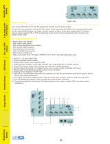
Figure 2-1. The DBS cabinet (DBS 96 shown) ................................................................. 2-3
Figure 2-2. The DBS cabinet (DBS 96 shown) ................................................................. 2-3
Figure 2-3. Trunk, line, and peripheral connections .......................................................... 2-4
Figure 2-4. Slot labels for printed circuit packages ........................................................... 2-9
Figure 3-1. Cover removal ................................................................................................. 3-3
Figure 3-2. Cabinet mounting bracket ...............................................................................3-4
Figure 3-3. Cabinet wall-mounting ...................................................................................3-4
Figure 3-4. Cabinet ground screw .....................................................................................3-5
Figure 3-5. SCC-B Switch 4 .............................................................................................. 3-6
Figure 3-6. CPC Strap S1 .................................................................................................. 3-7
Figure 3-7. Printed circuit card installation .......................................................................3-8
Figure 3-8. Battery location, DBS 40 ..............................................................................3-10
Figure 3-9. Battery tray, DBS 72 and 96 ......................................................................... 3-11
Figure 3-10. Battery pack connection, DBS 72 and 96 ..................................................... 3-12
Figure 3-11. Wall-mount adaptor removal ........................................................................ 3-13
Figure 3-12. Wall-mount adaptor replacement ..................................................................3-14
Figure 3-13. Handset guide insertion for wall-mounting, key phone ................................ 3-14
Figure 3-14. Desk stand removal for DSLT wall mounting .............................................. 3-15
Figure 3-15. Desk stand attachment for DSLT wall mounting ......................................... 3-16
Figure 3-16. Handset guide insertion for wall-mounting, DSLT ...................................... 3-16
Figure 3-17. CPC memory clear switch ............................................................................3-17
Figure 3-18. Test telephone connection ............................................................................3-19
Figure 4-1. DBS trunk connections (DBS 96) ...................................................................4-3
Figure 4-2. L-TRK Card Strap J1 and Switch Locations ................................................. 4-7
Figure 4-3. Attaching Caller ID Card to the L-TRK Card ................................................ 4-8
Figure 4-4. -48Vpower supply installation ...................................................................... 4-10
Figure 4-5. Connector 4 (CN4) strapping, Sync Unit ...................................................... 4-21
Figure 4-6. T1 Sync Unit installation .............................................................................. 4-22
Figure 4-7. T1 MDF card installation ..............................................................................4-23
Figure 4-8. Sync Unit and T1 connection, single-cabinet installation ............................ 4-24
Figure 4-9. RJ48 pinouts, CN1 connector .......................................................................4-25
Figure 4-10. T1 cabinet connections, single-cabinet installation ...................................... 4-26
Figure 4-11. Sync cable connections, double-cabinet with a T1 in the slave .................... 4-28
Figure 4-12. Clock sync cable and sync cable connections, double-cabinet installation .. 4-30
Figure 4-13. DBS extension connections .......................................................................... 4-31
Figure 4-14. SLT ringer box installation ..........................................................................4-38
Figure 4-15. EMI filter installation (DBS 40 only) ...........................................................4-40
Figure 4-16. DSS/72 connection using one cable with two pairs. ..................................... 4-42
Figure 4-17. EM/24 connection using one cable with two pairs .......................................4-43
Figure 4-18. Trunk or extension expansion ....................................................................... 4-45
Figure 5-1. RS-232C connection ......................................................................................5-4

List of Figures
Section 300-Programming
viii DBS Manual - Revised April 2000 DBS-2.3/9.2-300
Figure 5-2. SMDR Format for CPC-AII and CPC-B Version 3.1 or higher ..................... 5-5
Figure 5-3. RAI connection............................................................................................... 5-7
Figure 5-4. Installation of music-on-hold and background music ..................................... 5-9
Figure 5-5. Cable punch-out plate, OPX Adaptor ........................................................... 5-11
Figure 5-6. OPX installation ............................................................................................ 5-13
Figure 5-7. External zone paging installation .................................................................. 5-15
Figure 5-8. External general page/UNA installation ....................................................... 5-16
Figure 5-9. External ringer (UNA device) installation .................................................... 5-18
Figure 5-10. Cable punch-out plate, Power Failure Unit .................................................. 5-20
Figure 5-11. Power Failure Unit (PFU) installation .......................................................... 5-21
Figure 5-12. Cable punch-out plate, Voice Announce Unit .............................................. 5-24
Figure 5-13. Extension cord connection to the VAU ....................................................... 5-25
Figure 5-14. Voice Announce Unit (VAU) installation ................................................... 5-25
Figure 5-15. Cable punch-out plate, Door Box Adaptor ................................................... 5-29
Figure 5-16. Installation of the door box, door opener, and door sensor ..........................5-30
Figure 5-17. Cable punch-out plate, Door Box Adaptor ................................................... 5-31
Figure 5-18. Installation of the door box, door opener ...................................................... 5-32
Figure 5-19. Connections to the Door Box Adaptor ........................................................ 5-33
Figure 5-20. Cable punch-out plate, SLTA .......................................................................5-34
Figure 5-21. SLTA installation ......................................................................................... 5-36
Figure 6-1. Slot usage for two-cabinet systems, DBS 40 + DBS 40 ................................. 6-4
Figure 6-2. Slot usage for two-cabinet systems, DBS 72 + DBS 40 ................................. 6-5
Figure 6-3. Slot usage for two-cabinet systems, DBS 72 + DBS 72 ................................. 6-6
Figure 6-4. Slot usage for two-cabinet systems, DBS 96 + DBS 40 ................................. 6-7
Figure 6-5. Slot usage for two-cabinet systems, DBS 96 + DBS 72 ................................. 6-8
Figure 6-6. Slot usage for two-cabinet systems, DBS 96 to DBS 96 ................................ 6-9
Figure 6-7. Strap 3, MFR card .........................................................................................6-10
Figure 6-8. Double-cabinet installation ...........................................................................6-11
Figure 6-9. CBL-S to Connector Panel connection, slave cabinet ..................................6-11

Section 300-Installation List of Tables
DBS-2.3/9.2-300 DBS Manual - Revised April 2000 ix
List of Tables
Table 1-1. DBS model numbers .......................................................................................1-1
Table 1-2. FCC information ............................................................................................. 1-2
Table 1-3. Interface information ...................................................................................... 1-2
Table 2-1. Trunk and extension capacities according to system size ............................... 2-5
Table 2-2. Printed circuit card descriptions and maximums ............................................ 2-6
Table 2-3. Printed circuit package slot usage ................................................................... 2-8
Table 2-4. CPC/SCC features ........................................................................................... 2-9
Table 3-1. Battery backup packages for the DBS 40, 72, and 96 ....................................3-9
Table 4-1. Main trunks and expansion trunks provided with each system type .............. 4-4
Table 4-2. Pinouts and trunk numbers for the main trunk connector.............................. . 4-5
Table 4-3. Pinouts and trunk numbers for trunk expansion connector CN1 .................... 4-6
Table 4-4. -48V current consumption for ground-start and DID trunks .......................... 4-9
Table 4-5. -48V power supplies tested with the DBS ..................................................... 4-9
Table 4-6. T1 Hardware requirements for single-cabinet systems ................................. 4-11
Table 4-7. T1 Hardware requirements for double-cabinet systems ............................... 4-12
Table 4-8. T1 slot usage for two-cabinet systems .......................................................... 4-13
Table 4-9. T1 and analog trunk assignments, DBS 40 ................................................... 4-14
Table 4-10. T1 and analog trunk assignments, DBS 72 ................................................... 4-14
Table 4-11. T1 and analog trunk assignments, DBS 96 ................................................... 4-15
Table 4-12. Maximum T1 assignments for two-cabinet systems ..................................... 4-15
Table 4-13. T1 and analog trunk assignments, DBS 40 + 40 (16-channel fractional T1 in the
slave) 4-16
Table 4-14. T1 and analog trunk assignments, DBS 72 + DBS 72 (24-channel T1 in the slave)
4-16
Table 4-15. T1 and analog trunk assignments, DBS 96 + DBS 40 (24-channel T1 in the master;
16-channel T1 in the slave) 4-17
Table 4-16. T1 and analog trunk assignments, DBS 96 + DBS 72 (24-channel T1 in the master;
24-channel T1 in the slave) 4-18
Table 4-17. T1 and analog trunk assignments, DBS 96 + DBS 96 (24-channel T1 in the master;
24-channel T1 in the slave) 4-19
Table 4-18. Extension ports provided with each system ................................................. 4-32
Table 4-19. Pinouts and color codes for extension connector CN12 ............................... 4-33
Table 4-20. Pinouts and color codes for extension connector CN13 ............................... 4-34
Table 4-21. Pinouts and color codes for extension connector CN14 ............................... 4-35
Table 4-22. Pinouts and color codes for extension expansion connector CN1 ................ 4-36
Table 5-1. RS-232C pin designations used for CN6 ........................................................ 5-3
Table 5-2. RAI compatibility ........................................................................................... 5-6
Table 5-3. Maximum distances for direct connection to OPX stations ........................ 5-10
Table 5-4. Switch settings for SW1, VAU ..................................................................... 5-22
Table 5-5. Switch settings for delay answer timing, VAU ........................................... 5-23
Table 5-6. Switch settings for DTMF detection timing, VAU ....................................... 5-23

List of Tables
Section 300-Installation
x DBS Manual - Revised April 2000 DBS-2.3/9.2-300
Table 5-7. Switch settings for wait timing between dialed digits, VAU ....................... 5-23
Table 5-8. Switch settings for abbreviated dialing digit length, VAU ........................... 5-24
Table 5-9. Maximum distances for SLTA installation ................................................... 5-35
Table 6-1. Trunk and extension port maximums for double-cabinet systems ................. 6-3
Table 7-1. Input power .....................................................................................................7-3
Table 7-2. Power consumption and heat generation ........................................................ 7-3
Table 7-3. Battery backup capacity .................................................................................. 7-3
Table 7-4. Temperature and humidity requirements ........................................................ 7-4
Table 7-5. Dimensions and weight, single-cabinet systems and phones ......................... 7-4
Table 7-6. Dimensions for two-cabinet systems ..............................................................7-4
Table 7-7. Trunk and line capacities ................................................................................ 7-5
Table 7-8. Feature-related capacities ............................................................................... 7-5
Table 7-9. Hardware maximums for single-cabinet systems .......................................... 7-7
Table 7-10. Hardware maximums for double-cabinet systems ........................................ 7-10
Table 7-11. Maximum cabling distances ......................................................................... 7-13
Table 7-12. Voice path from KTELs to DBS ................................................................... 7-14
Table 7-13. Data communications ports ..........................................................................7-14
Table 7-14. Signaling to CO ............................................................................................ 7-15
Table 7-15. Signaling levels ............................................................................................. 7-15
Table 7-16. Transmission specifications ..........................................................................7-15
Table 7-17. Tone Plan ...................................................................................................... 7-16
Table 7-18. DTMF frequencies ........................................................................................ 7-17

Section 300-Installation About This Manual
DBS-2.3/9.2-300 DBS Manual - Revised April 2000 xi
About This Manual
Purpose
This manual provides installation instructions for the Digital Business System
(DBS). The following table summarizes the purpose of each chapter.
Related Information
Appendix A and Appendix B, located in the back of this manual.
For instructions on DBS programming, see Programming Guidance (Section
400).
For detailed descriptions of DBS features, see Feature Operation (Section
700).
Chapter
No.
Title Purpose
1 Requirements Includes DBS model numbers and FCC information that
may be required during installation. In addition,
environmental requirements are included to ensure proper
operation.
2 System Overview Provides an overview of the DBS. The overview includes
descriptions of the cabinet, system configurations, printed
circuit cards, and the call processor.
3 Cabinet Installation Explains how to install and power up the cabinet. Before
you begin installation, be sure to read Chapter 1 -
“Requirements.”.
4 Trunks and Lines Describes trunk and line installation. See the “Peripheral
Equipment” chapter for instructions on connecting
peripheral equipment through trunks or lines.
5 Peripheral
Equipment
Describes peripheral equipment installation. Some
peripheral equipment also requires trunk and/or line
interfaces (door phones or power failure units, for
example). For information on trunk and line connections,
see Chapter 4.
6 Double-Cabinet
Systems
Explains installation procedures for two-cabinet systems.
7 Specifications Contains frequently referenced DBS specifications.

About This Manual
Section 300-Installation
xii DBS Manual - Revised April 2000 DBS-2.3/9.2-300

DBS-2.3/9.2-300 DBS Manual - Revised April 2000 1-1
Chapter 1. Requirements
This chapter includes DBS model numbers and FCC information that may be
required during installation. In addition, environmental requirements for proper
operation are included.
This chapter covers the following topics:
Model Numbers
Table 1-1. DBS model numbers
FCC Requirements
General Requirements
• The Federal Communications Commission (FCC) has established Rules
which permit the DBS to be directly connected to the telephone network.
Standardized jacks are used for these connections. This equipment should
not be used on party lines or coin lines.
• Key FCC information appears in the following table.
• Before connecting the DBS, provide the telephone company with the
following information
Topic
Page
1-1
FCC Requirements 1-1
Environmental Requirements 1-4
Cleaning 1-5
DBS System Model Number
DBS 40 VB-43030
DBS 72 VB-43050
DBS 96 VB-43060

Section 300-Installation Chapter 1. Requirements
DBS-2.3/9.2-300 DBS Manual - Revised April 2000 1-2
Table 1-2. FCC information
Table 1-3. Interface information
• This equipment complies with Part 68 of the FCC Rules. On the left cover
panel of this equipment is a label that contains, among other information, the
FCC registration number and Ringer Equivalence Number (REN) for this
equipment. If requested, provided this information to your telephone
company.
• If the DBS telephone equipment caused harm to the Telephone Network, the
Telephone Company may discontinue your service temporarily. If possible,
they will notify you in advance. But if advance notice isn’t practical, you
will be notified as soon as possible. You will be advised of your right to file
a complaint with the FCC.
• Under the FCC Rules, no customer is authorized to repair this equipment.
This restriction applies regardless of whether the equipment is in or out of
Item Specification
FCC Registration
Number
When used as a key system: ACK4A4-60490-KF-E
When used as a PBX: ACK4A4-60489-MF-E
Ringer Equivalence 0.5B *
Network Address
Signaling Code
E
* The ringer equivalence number (REN) is useful to determine the quantity of
devices that you may connect to your telephone line and still have all of those
devices ring when your number is called. In most areas, the sum of the RENs
of all devices on any one line should not exceed five (5.0). To be certain of
the number of devices you may connect to your line, as determined by the
REN, you should call your telephone company to determine the maximum
REN for your calling area.
Port Type
Type of
Interface
USOC Jack
Connector
Service
Order Code*
Facility Interface
Code
Loop Start
Trunk
2-wire loop RJ21X 9.0F 02LS2
Ground Start
Trunk
2-wire ground RJ21X 9.0F 02GS2
DID Trunk 2-wire DID RJ21X 9.0F 02RV2-T
T1 Trunk T1 RJ48C 6.0F 04DU9-DN,
04DU9-1SN
OPX Adaptor OPX RJ21X (at
DBS DBS)
9.0F 0L13A
0L13B
0L13C (recommended)

Chapter 1. Requirements
Section 300-Installation
1-3 DBS Manual - Revised April 2000 DBS-2.3/9.2-300
warranty. However, the customer may replace fuses, and plug-in cards, as
needed.
• The Telephone Company may make changes in its facilities, equipment,
operations or procedures, that could affect the proper operation of your
equipment. If they do, you will be given advance notice so as to give you an
opportunity to maintain uninterrupted service.
• The Digital Key Telephones designed for use with this system are hearing
aid compatible.
• This equipment is capable of providing users access to interstate providers
of operator services through the use of access codes. Modification of this
equipment by call aggregators to block access dialing codes is a violation of
the Telephone Operator Consumers Act of 1990.
• If you experience trouble with the DBS, please contact Panasonic
Communication & Systems Company, Business Telephone Systems Division,
Two Panasonic Way Panazip 7B-3, Secaucus, NJ 07094 (Phone: (1-800-822-
0909) for repair/warranty information. Upon establishing contact, properly
identify the equipment, along with your company name/service center, and
address. The telephone company may ask you to disconnect this equipment from
the network until the problem has been corrected.
• The software contained in the DBS to allow user access to the network
must be upgraded to recognize newly established network area codes and
exchange codes as they are placed in service.
- Failure to upgrade the premises systems of peripheral equipment
to recognize the new codes as they are established will restrict
the customer and the customer’s employees from gaining access
to the network and to these codes.
- Bell Communications Research (Bellcore) publishes the North
American Numbering Plan (NANP) information in paper,
microfiche and tape. An abbreviated summary of the newly
established area codes and exchange codes is also available.
Bellcore may be contacted on (908) 699 6700 to obtain
appropriate information to keep customer equipment upgraded.
DID Requirements
Allowing this equipment to be operated in such a manner as to not provide for
proper answer supervision is a violation of Part 68 of the FCC Rules.
Proper answer supervision is when:
A. This equipment returns answer supervision to the PSTN when DID calls are:
- Answered by the called station

Section 300-Installation Chapter 1. Requirements
DBS-2.3/9.2-300 DBS Manual - Revised April 2000 1-4
- Answered by the attendant
- Routed to a recorded announcement that can be administered by
the CPE user
- Routed to a dial prompt.
B. This equipment provides answer supervision on all DID calls forwarded to
the PSTN. Permissible exceptions are:
- A call is unanswered
- A busy tone is received
- a reorder tone is received
T1 Requirements
This device must only be connected to the T1 network connected behind an
FCC Part 68 registered channel service unit. Direct connection is not allowed.
Environmental Requirements
Temperature:
The environment should be free from excessive temperatures in
order to avoid component damage. Room temperatures should be 32 to 104° F
(0 to 40° C).
Humidity:
The environment should be free from excessive humidity, which
may rust metallic parts and degrade performance. Do not install the system
where humidity could condense on its surfaces. Relative humidity ranges
should be between 30 and 90 percent.
Ventilation:
Adequate ventilation must be provided to allow upward air
circulation through the cabinet grille.
Gas and airborne particles:
To avoid corrosion or oxidation of electrical
contacts, the environment should be free from airborne particles and corrosive
gas.
Electrical noise:
The environment should be free from excessive electrical
noise, which could disturb the operation of digital circuits. The system should
be located at least 10 ft. (3 m) away from welders, dimmers, or other high-
current machines. Phones connected to the system should not be located near
fluorescent lamps, air conditioners, washing machines, TVs, or radios.
Vibration:
The environment should be free from excessive vibration, which
could loosen components.
Water Exposure:
Because the DBS is an electric device, exposure to water is
dangerous. Do not place anything containing water on the system. Do not install

Chapter 1. Requirements
Section 300-Installation
1-5 DBS Manual - Revised April 2000 DBS-2.3/9.2-300
under overhead plumbing, sprinkler system valves, or in areas that are
susceptible to flooding.
Lighting:
Sufficient lighting is required for testing and maintenance.
Lightning Protection/Grounding:
The system must be properly grounded to
protect from lightning damage. The following UL conditions must be met to
ensure proper grounding. (For grounding instructions, see page 3-5.)
• Supplemental and independent equipment grounding conductors are to be
installed between the system and the wiring system ground.
• One of the equipment grounding conductors must be a conductor that is as
large or larger than the ungrounded branch-circuit supply conductors. The
equipment grounding conductor is to be installed as part of the circuit that
supplies the system and is to be connected to ground at the service
equipment. Bare, covered, or insulated grounding conductors are acceptable.
Individually covered or insulated grounding conductors should have a
continuous outer finish that is either green or green with one or more yellow
stripes. The equipment grounding conductor should be connected to ground
at the service equipment.
• The other equipment grounding conductor shall comply with the general
rules for grounding contained in Article 250 of the National Electric Code,
NFPA 70, but its connection to ground shall not depend on the cord and plug
of the system.
• The attachment-plug receptacles of the same type as that used by the
systems that are in the vicinity of the DBS are all to be of a grounding type,
and the equipment grounding conductors serving these receptacles are to be
connected to earth ground at the service equipment.
• A marking adjacent to the telecommunications jacks must instruct the user
to connect a supplementary equipment grounding conductor before any
telecommunication lines are connected to the product or system.
Cleaning
•Use a slightly damp cloth to clean the phones. The phones should never be
cleaned with benzene, paint thinner, or other solvents.

Chapter 1. Requirements
Section 300-Installation
1-6 DBS Manual - Revised April 2000 DBS-2.3/9.2-300

DBS-2.3/9.2-300 DBS Manual - Revised April 2000 2-1
Chapter 2. System Overview
This chapter gives an overview of the Digital Business System (DBS). This
overview includes descriptions of the DBS cabinet, system configurations,
printed circuit cards, and the call processor.
This chapter covers the following topics::
Topic
Page
Cabinet Description 2-3
Configurations 2-5
Printed Circuit Cards 2-6
Processor Description 2-9

2-2 DBS Manual - Revised April 2000 DBS-2.3/9.2-300
/