Page is loading ...

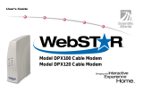
User Guide
SBV5120 Series
VoIP Cable Modem

ii SBV5120 Series VoIP Cable Modem User Guide
Home
X
ExitPrint
Introduction Installation Troubleshooting Glossary License
WARNING: TO PREVENT FIRE OR SHOCK HAZARD, DO NOT EXPOSE THIS PRODUCT TO RAIN OR
MOISTURE. THE UNIT MUST NOT BE EXPOSED TO DRIPPING OR SPLASHING. DO NOT PLACE OBJECTS
FILLED WITH LIQUIDS, SUCH AS VASES, ON THE UNIT.
CAUTION: THIS PRODUCT WAS QUALIFIED UNDER TEST CONDITIONS THAT INCLUDED THE USE OF
THE SUPPLIED CABLES BETWEEN SYSTEMS COMPONENTS. TO ENSURE REGULATORY AND SAFETY
COMPLIANCE, USE ONLY THE PROVIDED POWER AND INTERFACE CABLES AND INSTALL THEM PROPERLY.
CAUTION: DIFFERENT TYPES OF CORD SETS MAY BE USED FOR CONNECTIONS TO THE MAIN SUPPLY
CIRCUIT. USE ONLY A MAIN LINE CORD THAT COMPLIES WITH ALL APPLICABLE PRODUCT SAFETY
REQUIREMENTS OF THE COUNTRY OF USE.
CAUTION: INSTALLATION OF THIS PRODUCT MUST BE IN ACCORDANCE WITH NATIONAL WIRING
CODES AND CONFORM TO LOCAL REGULATIONS.
CAUTION: DO NOT OPEN THE UNIT. DO NOT PERFORM ANY SERVICING OTHER THAN THAT CONTAINED
IN THE INSTALLATION AND TROUBLESHOOTING INSTRUCTIONS. REFER ALL SERVICING TO QUALIFIED
SERVICE PERSONNEL.
CAUTION: CHANGES AND MODIFICATIONS NOT EXPRESSLY APPROVED BY MOTOROLA FOR
COMPLIANCE COULD VOID USER’S AUTHORITY TO OPERATE THE EQUIPMENT.
When using this device, basic safety precautions should always be followed to reduce the risk of fire, electric
shock and injury to persons, including the following:
• Read all of the instructions listed here and/or in the user manual before you operate this equipment. Give
particular attention to all safety precautions. Retain the instructions for future reference.
• This device must be installed and used in strict accordance with manufacturer’s instructions as described in
the user documentation that comes with the product.
• Comply with all warning and caution statements in the instructions. Observe all warning and caution symbols
that are affixed to this equipment.
• Do not overload outlets or extension cords, as this can result in a risk of fire or electric shock. Overloaded AC
outlets, extension cords, frayed power cords, damaged or cracked wire insulation, and broken plugs are
dangerous. They may result in a shock or fire hazard.
• Route power supply cords so that they are not likely to be walked on or pinched by items placed upon or
against them. Pay particular attention to cords where they are attached to plugs and convenience
receptacles, and examine the point where they exit from the product.
• Place this equipment in a location that is close enough to an electrical outlet to accommodate the length of
the power cord.
• Place unit to allow for easy access when disconnecting the power cord of the device from the AC wall outlet.
• Do not connect the plug into an extension cord, receptacle, other outlet unless the plug can be fully inserted
with no part of the blades exposed.
• Place this equipment on a stable surface.
• Postpone cable modem installation until there is no risk of thunderstorm or lightning activity in the area.
• Avoid using this product during an electrical storm. There may be a risk of electric shock from lightning. For
added protection for this product during a lightning storm, or when it is left unattended and unused for long

iii SBV5120 Series VoIP Cable Modem User Guide
Home
X
ExitPrint
Introduction Installation Troubleshooting Glossary License
periods of time, unplug it from the wall outlet, and disconnect the cable system. This will prevent damage to
the product due to lightning and power surges.
• It is recommended that the customer install an AC surge protector in the AC outlet to which this device is
connected. This is to avoid damaging the equipment by local lightning strikes and other electrical surges.
• Do not cover the device, or block the airflow to the device with any other objects. Keep the device away from
excessive heat and humidity and keep the device free from vibration and dust.
• Wipe the unit with a clean, dry cloth. Never use cleaning fluid or similar chemicals. Do not spray cleaners
directly on the unit or use forced air to remove dust.
• Avoid damaging the cable modem with static by touching the coaxial cable when it is attached to the earth
grounded coaxial cable TV wall outlet.
• Always first touch the coaxial cable connector on the cable modem when disconnecting or re-connecting USB
or Ethernet cable from the cable modem or the user’s PC.
• Operate this product only from the type of power source indicated on the product’s marking label. If you are
not sure of the type of power supplied to your home, consult your dealer or local power company.
• Upon completion of any service or repairs to this product, ask the service technician to perform safety checks
to determine that the product is in safe operating condition.
Be sure that the outside cable system is grounded, so as to provide some protection against voltage surges and
built-up static charges. Article 820-20 of the NEC (Section 54, Part I of the Canadian Electrical Code) provides
guidelines for proper grounding and, in particular, specifies the CATV cable ground shall be connected in the
grounding system of the building, as close to the point of cable entry as practical.
FCC Compliance Class B Digital Device
This device complies with part 15 of the FCC Rules. Operation is subject to the following two conditions: (1) This
device may not cause harmful interference, and (2) this device must accept any interference received, including
interference that may cause undesired operation.
Note: This equipment has been tested and found to comply with the limits for a Class B digital device, pursuant to
part 15 of the FCC Rules. These limits are designed to provide reasonable protection against harmful interference
in a residential installation. This equipment generates, uses and can radiate radio frequency energy and, if not
installed and used in accordance with the instructions, may cause harmful interference to radio communications.
However, there is no guarantee that interference will not occur in a particular installation. If this equipment does
cause harmful interference to radio or television reception, which can be determined by turning the equipment off
and on, the user is encouraged to try to correct the interference by one or more of the following measures:
• Reorient or relocate the receiving antenna.
• Increase the separation between the equipment and receiver.
• Connect the equipment into an outlet on a circuit different from that to which the receiver is connected.
• Consult the dealer or an experienced radio/TV technician for help.

iv SBV5120 Series VoIP Cable Modem User Guide
Home
X
ExitPrint
Introduction Installation Troubleshooting Glossary License
Canada - Industry Canada (IC)
This Class B digital device complies with Canadian ICES-003.
Cet appareil numérique de la classe B est conforme à la norme NMB-003 du Canada.
Regulatory, Safety, Software License, and Warranty Information Card
This product is provided with a separate Regulatory, Safety, Software License, and Warranty Information card. If
one is not provided with this product, please ask your service provider or point-of-purchase representative, as the
case may be.
• THIS PRODUCT IS IN COMPLIANCE WITH ONE OR MORE OF THE STANDARDS LISTED ON THE
REGULATORY, SAFETY, SOFTWARE LICENSE, AND WARRANTY INFORMATION CARD. NOT ALL
STANDARDS APPLY TO ALL MODELS.
• NO WARRANTIES OF ANY KIND ARE PROVIDED BY MOTOROLA WITH RESPECT TO THIS PRODUCT,
EXCEPT AS STATED ON THE REGULATORY, SAFETY, SOFTWARE LICENSE, AND WARRANTY
INFORMATION CARD. MOTOROLA’S WARRANTIES DO NOT APPLY TO PRODUCT THAT HAS BEEN
REFURBISHED OR REISSUED BY YOUR SERVICE PROVIDER.
Copyright © 2004 by Motorola, Inc.
All rights reserved. No part of this publication may be reproduced in any form or by any means or used to make any derivative work (such as
translation, transformation or adaptation) without written permission from Motorola, Inc.
Motorola reserves the right to revise this publication and to make changes in content from time to time without obligation on the part of Motorola
to provide notification of such revision or change. Motorola provides this guide without warranty of any kind, either implied or expressed,
including, but not limited to, the implied warranties of merchantability and fitness for a particular purpose. Motorola may make improvements or
changes in the product(s) described in this manual at any time.
MOTOROLA, Intelligence Everywhere, and the Stylized M Logo are registered in the US Patent & Trademark Office. Microsoft, Windows, Windows
Me, and Windows NT are registered trademarks and
Windows XP is a trademark of
Microsoft Corporation. Microsoft Windows screen shots are
used by permission of Microsoft Corporation. DOCSIS is a registered trademark of CableLabs. Linux is a registered trademark of Linus Torvalds.
Solaris, Java, and all Java-based marks trademarks or registered trademarks of Sun Microsystems, Inc. in the United States and other countries.
Acrobat Reader is a registered trademark of Adobe Systems, Inc. UNIX is a registered trademark of the Open Group in the United States and other
countries. All other
product or service names are the property of their respective owners. © Motorola, Inc. 2004.

v SBV5120 Series VoIP Cable Modem User Guide
Home
X
ExitPrint
Introduction Installation Troubleshooting Glossary License
Contents
Introduction . . . . . . . . . . . . . . . . . . . . . . . . . . . . . . . . . . . . . . . . . . . . . . . . . . . . . . . . . . . . . . . . 1
Top and Front Panel . . . . . . . . . . . . . . . . . . . . . . . . . . . . . . . . . . . . . . . . . . . . . . . . . . . . . . . . . . . . . . . . . . . . . . . . . . .2
Rear Panel . . . . . . . . . . . . . . . . . . . . . . . . . . . . . . . . . . . . . . . . . . . . . . . . . . . . . . . . . . . . . . . . . . . . . . . . . . . . . . . . . .3
Before You Begin. . . . . . . . . . . . . . . . . . . . . . . . . . . . . . . . . . . . . . . . . . . . . . . . . . . . . . . . . . . . 3
Precautions . . . . . . . . . . . . . . . . . . . . . . . . . . . . . . . . . . . . . . . . . . . . . . . . . . . . . . . . . . . . . . . . . . . . . . . . . . . . . . . . .4
Signing Up for Service . . . . . . . . . . . . . . . . . . . . . . . . . . . . . . . . . . . . . . . . . . . . . . . . . . . . . . . . . . . . . . . . . . . . . . . . .5
Computer System Requirements . . . . . . . . . . . . . . . . . . . . . . . . . . . . . . . . . . . . . . . . . . . . . . . 6
Ethernet Card . . . . . . . . . . . . . . . . . . . . . . . . . . . . . . . . . . . . . . . . . . . . . . . . . . . . . . . . . . . . . . . . . . . . . . . . . . . . . . . .6
USB Connection . . . . . . . . . . . . . . . . . . . . . . . . . . . . . . . . . . . . . . . . . . . . . . . . . . . . . . . . . . . . . . . . . . . . . . . . . . . . . .6
Installation and Configuration Overview. . . . . . . . . . . . . . . . . . . . . . . . . . . . . . . . . . . . . . . . . 7
Cabling and Startup for a Single User . . . . . . . . . . . . . . . . . . . . . . . . . . . . . . . . . . . . . . . . . . . . . . . . . . . . . . . . . . . . .7
Setting Up a USB Driver . . . . . . . . . . . . . . . . . . . . . . . . . . . . . . . . . . . . . . . . . . . . . . . . . . . . . . . . . . . . . . . . . . . . . . . .9
Setting Up a USB Driver in Windows 98 . . . . . . . . . . . . . . . . . . . . . . . . . . . . . . . . . . . . . . . . . . . . . . . . . . . . . . . .10
Setting Up a USB Driver in Windows Me . . . . . . . . . . . . . . . . . . . . . . . . . . . . . . . . . . . . . . . . . . . . . . . . . . . . . . . .14
Setting Up a USB Driver in Windows 2000 . . . . . . . . . . . . . . . . . . . . . . . . . . . . . . . . . . . . . . . . . . . . . . . . . . . . . .15
Setting Up a USB Driver in Windows XP . . . . . . . . . . . . . . . . . . . . . . . . . . . . . . . . . . . . . . . . . . . . . . . . . . . . . . . .18
Configuring TCP/IP . . . . . . . . . . . . . . . . . . . . . . . . . . . . . . . . . . . . . . . . . . . . . . . . . . . . . . . . . . . . . . . . . . . . . . . . . .19
Configuring TCP/IP in Windows 95, 98, or Windows Me . . . . . . . . . . . . . . . . . . . . . . . . . . . . . . . . . . . . . . . . . . . .20
Configuring TCP/IP in Windows 2000 . . . . . . . . . . . . . . . . . . . . . . . . . . . . . . . . . . . . . . . . . . . . . . . . . . . . . . . . . .22
Configuring TCP/IP in Windows XP . . . . . . . . . . . . . . . . . . . . . . . . . . . . . . . . . . . . . . . . . . . . . . . . . . . . . . . . . . . .26
Verifying the IP Address . . . . . . . . . . . . . . . . . . . . . . . . . . . . . . . . . . . . . . . . . . . . . . . . . . . . . . . . . . . . . . . . . . . . . . .29
Verifying the IP Address in Windows 95, Windows 98, or Windows Me . . . . . . . . . . . . . . . . . . . . . . . . . . . . . . . .29
Verifying the IP Address in Windows 2000 or Windows XP . . . . . . . . . . . . . . . . . . . . . . . . . . . . . . . . . . . . . . . . . .30
Renewing Your IP Address . . . . . . . . . . . . . . . . . . . . . . . . . . . . . . . . . . . . . . . . . . . . . . . . . . . . . . . . . . . . . . . . . . . .31
Cabling for Multiple Users . . . . . . . . . . . . . . . . . . . . . . . . . . . . . . . . . . . . . . . . . . . . . . . . . . . 32
Ethernet and USB . . . . . . . . . . . . . . . . . . . . . . . . . . . . . . . . . . . . . . . . . . . . . . . . . . . . . . . . . . . . . . . . . . . . . . . . . . .32
Ethernet . . . . . . . . . . . . . . . . . . . . . . . . . . . . . . . . . . . . . . . . . . . . . . . . . . . . . . . . . . . . . . . . . . . . . . . . . . . . . . . . . . .33
Troubleshooting . . . . . . . . . . . . . . . . . . . . . . . . . . . . . . . . . . . . . . . . . . . . . . . . . . . . . . . . . . . 34
Front-Panel Lights and Error Conditions . . . . . . . . . . . . . . . . . . . . . . . . . . . . . . . . . . . . . . . . . . . . . . . . . . . . . . . .35
Removing the USB Driver . . . . . . . . . . . . . . . . . . . . . . . . . . . . . . . . . . . . . . . . . . . . . . . . . . . . . . . . . . . . . . . . . . . . .36
Removing the USB Driver from Windows 98 or Windows Me . . . . . . . . . . . . . . . . . . . . . . . . . . . . . . . . . . . . . . . .36
Removing the USB Driver from Windows 2000 . . . . . . . . . . . . . . . . . . . . . . . . . . . . . . . . . . . . . . . . . . . . . . . . . . .38
Removing the USB Driver from Windows XP . . . . . . . . . . . . . . . . . . . . . . . . . . . . . . . . . . . . . . . . . . . . . . . . . . . . .42
Contact Us . . . . . . . . . . . . . . . . . . . . . . . . . . . . . . . . . . . . . . . . . . . . . . . . . . . . . . . . . . . . . . . . 46
Frequently Asked Questions . . . . . . . . . . . . . . . . . . . . . . . . . . . . . . . . . . . . . . . . . . . . . . . . . 47
Glossary . . . . . . . . . . . . . . . . . . . . . . . . . . . . . . . . . . . . . . . . . . . . . . . . . . . . . . . . . . . . . . . . . . 49
Software License . . . . . . . . . . . . . . . . . . . . . . . . . . . . . . . . . . . . . . . . . . . . . . . . . . . . . . . . . . . 50

1 SBV5120 Series VoIP Cable Modem User Guide
Home
X
ExitPrint
Introduction Installation Troubleshooting Glossary License
Introduction
Congratulations on your new Motorola
®
SURFboard
®
Voice over Internet Protocol (VoIP) cable modem! It
provides high-speed access to the Internet and other online services. This VoIP cable modem transmits and
receives data much faster than traditional dial-up or ISDN modems because it receives data much faster than
other modems. Unlike a dial-up modem, your SURFboard VoIP cable modem is always online. Just open your
browser and surf!
You can use your high-speed, upgradeable VoIP cable modem to connect one or more computers in your home or
business to the Internet. You can connect:
• A single computer equipped with a Universal Serial Bus (USB) port directly to the USB port on the
SURFboard VoIP cable modem
• A single computer equipped with an Ethernet adapter directly to the Ethernet port on the SURFboard VoIP
cable modem
• Two computers, one to the USB port and one to the Ethernet port
• Up to 31 computers to a single SURFboard VoIP cable modem using an Ethernet hub, as shown in “Cabling
for Multiple Users” on page 32
You can connect up to two standard telephone lines using your SURFboard VoIP cable modem, supporting:
• Standard features such as Caller ID, Call Waiting, and Call Forwarding
• Software upgrades over the network to provide new or improved services
Easier!
Unlike dial-up modems or ISDN, you’re always on, always connected when using coaxial
cable for upstream communication. For easiest set-up, use the Installation Assistant on
the SURFboard VoIP Cable Modem CD-ROM.
Faster!
Your VoIP cable modem is up to 100 times faster than a dial-up modem. It lets you enjoy
surfing the Web without the long wait. Because many network and other factors can
affect performance, the actual speed will vary.
Better!
Your VoIP cable modem is made by the company with over 50 years of cable TV
expertise.

2 SBV5120 Series VoIP Cable Modem User Guide
Home
X
ExitPrint
Introduction Installation Troubleshooting Glossary License
Top and Front Panel
For added security, when using coaxial cable for upstream communication, you can press the Standby button (1)
to suspend your Internet connection. No data is transmitted or received from the Internet when the Standby light is
on. All other front-panel lights turn off until you press the Standby button again except the Tel 1 and Tel 2 LEDs.
The lights provide information about power, communications, and errors:
During normal operation, the Power, Receive, Send, and Online lights are on and the Link light flashes when the
VoIP cable modem is transferring data.
Key Light Flashing On
2Power Startup diagnostics in progress The VoIP cable modem is powered on.
3DS
(Downstream)
Scanning for a receive (downstream)
channel connection
The downstream channel is connected.
4US
(Upstream)
Scanning for a send (upstream)
channel connection
The upstream channel is connected.
5 Online Scanning for a network connection The startup process is complete.
6Link Transmitting or receiving data A device, such as a computer or hub, is connected to the
USB or Ethernet connectors on the back panel.
7Tel 1 Connected and activated,
telephone is off-hook (in use).
Connected and activated, the telephone is on-hook
(not in use.)
8Tel 2 Connected and activated,
telephone is off-hook (in use).
Connected and activated, the telephone is on-hook
(not in use.)
9 Standby This light does not flash Internet service is blocked because the Standby button
was pressed. If this light is on, all other lights are off.
The model number on your VoIP cable
modem may be different than in the
illustrations and screen images in this
guide.
SBV5120
SURFboard®
Cable Modem
P
O
W
E
R
D
S
U
S
O
N
L
I
N
E
L
I
N
K
T
E
L
1
T
E
L
2
S
T
A
N
D
B
Y
1
2
3
4
5
6
7
8
9

3 SBV5120 Series VoIP Cable Modem User Guide
Home
X
ExitPrint
Introduction Installation Troubleshooting Glossary License
Rear Panel
The rear panel provides cabling connectors and the power receptacle.
Before You Begin
Before you begin the installation, check that you received the following items with your SURFboard VoIP cable
modem:
Key Item Description
1 & 2 Tel 1 and Tel 2 Telephone ports 1 and 2 provide connections for two telephone lines.
3 ETHERNET The Ethernet port provides a connection to Ethernet equipped computers using a cable
terminated with an RJ-45 connector.
4USB The USB port provides a connection to USB equipped computers.
5 Reset If you experience a problem, you can push this recessed button to reset the VoIP cable modem
(see “Troubleshooting” on page 34). Resetting may take some time (5 to 30 minutes) because
the VoIP cable modem must find and lock on the appropriate communications channels.
6 CABLE The CABLE port provides a connection to the coaxial cable (coax) outlet.
7+12VDC This connector provides power to the VoIP cable modem.
Item Description
Power
adapter or
cable
Connects to:
• the AC power outlet
• to a UPS
10/100Base-T
Ethernet cable
Connects to the Ethernet port
USB cable Connects to the USB port
CABLE
+12VDC
USB
TEL 2
TEL 1
ETHERNET
12&
3
4
5
6
7

4 SBV5120 Series VoIP Cable Modem User Guide
Home
X
ExitPrint
Introduction Installation Troubleshooting Glossary License
You will need 75-ohm coaxial cable with F-type connectors to connect your VoIP cable modem to the nearest
cable outlet. If a TV is connected to the cable outlet, you may need a 5-900 MHz RF splitter and a total of three
coaxial cables to connect both the TV and the VoIP cable modem. The coaxial cable and RF splitter are available
at consumer electronic stores. To connect your VoIP cable modem to an Ethernet hub, see the network
description in “Cabling for Multiple Users” on page 32. Check the documentation provided with your hub.
Precautions
Postpone VoIP cable modem installation until there is no risk of thunderstorm or lightning activity in the area.
To avoid damaging the VoIP cable modem with static electricity:
• Always first connect the coaxial cable to the grounded cable TV wall outlet.
• Before you connect or disconnect the USB or Ethernet cable from your VoIP cable modem or PC, always
touch the coaxial cable connector on the VoIP cable modem to release any static charges.
To prevent overheating the VoIP cable modem, do not block the ventilation holes on its sides.
Phone wire Connects the telephone to the cable system to provide telephony service
SURFboard VoIP
Cable Modem
CD-ROM
Contains the User Guide and USB drivers
Item Description
Caution
To comply with all national safety regulations, do not route the USB,
Ethernet, or telephone cables outside of the building.
CABLE
+12VDC
USBTEL 2TEL 1
ETHERNET
To avoid damaging your VoIP cable
modem or PC with static electricity:
Before you connect
or disconnect the
USB or Ethernet
cable, touch the
coaxial cable
connector on the
VoIP cable modem.
Always make the
wall connection
first.

5 SBV5120 Series VoIP Cable Modem User Guide
Home
X
ExitPrint
Introduction Installation Troubleshooting Glossary License
Do not open the VoIP cable modem. Refer all service to your cable service provider.
Wipe the VoIP cable modem with a clean, dry cloth. Never use cleaning fluid or similar chemicals. Do not spray
cleaners directly on the unit or use forced air to remove dust.
Caution
Signing Up for Service
You must sign up with a cable service provider to access the Internet and other online services.
To activate your service, call your local cable service provider.
To receive data service, you need to provide the MAC address printed on the bar code label marked CM HFC
MAC ID on the bottom of the cable modem. You can record it here:
00 : ______ : ______ : ______ : ______ : ______
To receive telephone service, you need to provide the MAC address printed on the bar code label marked MTA
MAC ID on the bottom of the cable modem. You can record it here:
00 : ______ : ______ : ______ : ______ : ______
You should ask your cable service provider the following questions:
• Do you have any special system requirements?
• When can I begin to use my VoIP cable modem?
Contact your cable service provider before connecting your VoIP cable
modem to your existing telephone wiring. Do not connect the telephone wire
to a traditional telephone (PSTN) service.
P/N: AAAAAA-BBB-00 ASSEMBLED IN: _________
S/N: PPPPMMYJJJSSSSSCAABBCCCC
CUSTOMER S/N: BCDFGHJKLMNP
HFC MAC ID: ABCDEF012345
USB CPE MAC ID: ABCDEF012345
MTA MAC ID: ABCDEF012345
MODEM NUMBER: 2345

6 SBV5120 Series VoIP Cable Modem User Guide
Home
X
ExitPrint
Introduction Installation Troubleshooting Glossary License
• Are there any files I need to download after I am connected?
• Do I need a user name or password to access the Internet or use e-mail?
Computer System Requirements
You can use any Web browser, such as Microsoft
®
Internet Explorer or Netscape Navigator
®
, with your
SURFboard VoIP cable modem.
For Microsoft Windows computers, the Installation Assistant application automatically checks your system
configuration.
You can start the Installation
Assistant from the Main Menu on the SURFboard VoIP Cable Modem
CD-ROM.
Your SURFboard VoIP cable modem is compatible with Microsoft Windows
®
, Macintosh
®
, and UNIX
®
computers.
Ethernet Card
You can use the Ethernet connection with any Windows, Macintosh, or UNIX computer equipped with a 10Base-T
or 10/100Base-T Ethernet card.
Windows
®
95, UNIX, or Macintosh computers must use the Ethernet connection.
If you use an Ethernet card, it must be installed in your computer before you install the VoIP cable modem. If it is
not installed, follow the installation instructions provided with your Ethernet card.
USB Connection
You can use the USB connection with any PC running Windows
®
98, Windows
®
2000, Windows Me
®
, or Windows
XP
™
that has a USB interface. The USB connection requires special USB driver software that is supplied on the
SURFboard VoIP Cable Modem CD-ROM.
You can upgrade your USB drivers from our Downloads page http://broadband.motorola.com/noflash/
usb_drivers.asp.

7 SBV5120 Series VoIP Cable Modem User Guide
Home
X
ExitPrint
Introduction Installation Troubleshooting Glossary License
Installation and Configuration Overview
To install and configure your VoIP cable modem for a single PC running Microsoft Windows, we recommend using
the
Installation
Assistant.
You can start the Installation
Assistant from the Main Menu on the SURFboard VoIP
Cable Modem
CD-ROM. In most cases, the Installation
Assistant automatically configures your VoIP cable modem.
Otherwise, to install and configure your VoIP cable modem:
1 Install the cables as described for your situation:
• “Cabling and Startup for a Single User” on page 7
• “Cabling for Multiple Users” on page 32
2 If you are using the USB port only, go to “Setting Up a USB Driver” on page 9. Ethernet users can skip this
step.
3 Configure TCP/IP and verify the IP address for your computer as described for your situation:
• “Configuring TCP/IP” on page 19
• Refer to your Macintosh or UNIX user manual for information regarding TCP/IP and IP Address
configuration.
Cabling and Startup for a Single User
Allow some time (5 to 30 minutes) to power up the first time because the SURFboard VoIP cable modem must find
and lock on the appropriate channels for communications.
1 Be sure your computer is on and the VoIP cable modem is unplugged.
2 Connect one end of the coaxial cable to the cable outlet or splitter. Connect the other end of the coaxial cable
to the CABLE connector on the VoIP cable modem. Hand-tighten the connectors to avoid damaging them.
3 Insert the SURFboard VoIP Cable Modem CD-ROM into your CD-ROM drive.
4 Connect one end of the telephone wire to the dial-up modem connector on the VoIP cable modem. Connect
the other end to a telephone jack.
CABLE
+12VDC
USBTEL 2TEL 1
ETHERNET
SURFboard VoIP cable modem
To electrical
outlet or UPS
(step 5)
To ca ble
outlet
(step 2)
Always connect coaxial
cable to the wall outlet
first.

8 SBV5120 Series VoIP Cable Modem User Guide
Home
X
ExitPrint
Introduction Installation Troubleshooting Glossary License
5 Plug the power cord into the +12VDC connector on the VoIP cable modem and the electrical outlet. For an
Uninterruptible Power Supply (UPS), plug the cord into the +12VDC connector on the VoIP cable modem and
the UPS and plug the UPS into the electrical outlet.
For a power adapter, plug the adapter into the POWER connector on the VoIP cable modem and the
electrical outlet. For a UPS, plug the cord into the POWER connector on the VoIP cable modem and the UPS
and plug the UPS into the electrical outlet. This turns on the SURFboard VoIP cable modem. You do not need
to unplug it when not in use.
6 Check that the lights on the VoIP cable modem front cycle through this sequence:
• Power flashes during the self-test and changes to solid green when the self-test is successfully complete.
• Receive flashes while scanning for the receive (downstream) channel and changes to solid green when it
is connected.
• Send flashes while scanning for the send (upstream) channel and changes to solid green when it is
connected. If you use the internal dial-up modem for upstream communication, you may hear it dial-up
and connect.
• Online flashes while the VoIP cable modem downloads configuration data and changes to solid green
when the download is complete.
7 Connect your computer to the VoIP cable modem using USB or Ethernet:
USB: Be sure the SURFboard VoIP Cable Modem CD-ROM is inserted in your CD-ROM drive. Connect the
USB cable to the USB port on the VoIP cable modem. Connect the other end to the USB port on your
computer. Then perform “Setting Up a USB Driver” on page 9.
Ethernet: Connect the provided straight-through Ethernet cable to the Ethernet connector on the VoIP cable
modem. Connect the other end to the Ethernet port on your computer. Ethernet users do not need to set up
USB.
8 Perform the procedures for “Configuring TCP/IP” on page 19.
CABLE
+12VDC
USBTEL 2TEL 1
ETHERNET
Caution
Do not connect both the Ethernet and USB cables to
the same computer. Connect to either Ethernet or
USB
Computer
SURFboard VoIP cable
modem

9 SBV5120 Series VoIP Cable Modem User Guide
Home
X
ExitPrint
Introduction Installation Troubleshooting Glossary License
9 To connect the telephone line, plug a phone wire into the Tel 1 connector. You can also connect a second
telephone line to the Tel 2 connector.
Setting Up a USB Driver
The following subsections describe setting up a USB driver. Perform the appropriate procedure for your Windows
version:
• “Setting Up a USB Driver in Windows 98” on page 10
• “Setting Up a USB Driver in Windows 2000” on page 15
• “Setting Up a USB Driver in Windows Me” on page 14
• “Setting Up a USB Driver in Windows XP” on page 18
When you finish setting up the USB driver, you can continue with “Configuring TCP/IP” on page 19.
The SURFboard VoIP cable modem USB driver does not support Macintosh or UNIX computers. For those
systems connect through Ethernet only.
Caution
Contact your cable service provider before connecting your VoIP cable
modem to your existing telephone wiring. Do not connect the telephone
wire to a traditional telephone (PSTN) service.
Be sure the phone connectors are neither connected together nor
connected to wall jacks on the same network.
Be sure the SURFboard VoIP Cable Modem
CD-ROM is inserted in your CD-ROM drive
before you plug in the USB cable.

10 SBV5120 Series VoIP Cable Modem User Guide
Home
X
ExitPrint
Introduction Installation Troubleshooting Glossary License
Setting Up a USB Driver in Windows 98
Be sure the SURFboard VoIP Cable Modem CD-ROM is inserted in your CD-ROM drive before you plug in the
USB cable. This CD contains the USB drivers and must be inserted and read by the PC before you connect the
VoIP cable modem to the PC.
1 Connect the VoIP cable modem to your computer with a USB cable. For further instructions, see “Cabling and
Startup for a Single User” on page 7. A few seconds after you complete the USB connection, the Add New
Hardware Wizard window is displayed:
2 Click Next.
3 Be sure “Search for the best driver for your device” is selected and click Next.
Although your SURFboard VoIP cable modem model number
may be different than in the images in this guide, the
procedure is the same.

11 SBV5120 Series VoIP Cable Modem User Guide
Home
X
ExitPrint
Introduction Installation Troubleshooting Glossary License
4 Be sure “CD-ROM drive” is the only box checked.
5 Click Next.
The message “Please wait while Windows searches for a new driver for this device” is displayed:
6 If your computer successfully locates the driver, skip to step 8.
If your computer does not locate the driver, the previous window is displayed again. Select Specify a
location and type the location of your CD-ROM drive.
To load the driver successfully, you may need to click Browse to manually select the driver file from the
CD-ROM. For the SBV5120, select the NetMotCM.sys file.
7 Click Next.

12 SBV5120 Series VoIP Cable Modem User Guide
Home
X
ExitPrint
Introduction Installation Troubleshooting Glossary License
8 Select The updated driver... and click Next.
If this window is not displayed, verify that the SURFboard VoIP Cable Modem CD-ROM is properly inserted in
the CD-ROM drive. If you still cannot find the correct driver file, click Cancel to cancel the installation and
perform the procedure for “Removing the USB Driver from Windows 98 or Windows Me” on page 34. Then
repeat this procedure.
9 After the window is displayed, click Next.
If a window with the message Copying Files... displays and asks for your CD-ROM drive, type your CD-ROM
drive letter (for example, “D:”) and click OK.
If an Insert Disk window similar to the one below is displayed, Windows 98 system files are needed to
complete the installation. To install the files, insert your Windows 98 CD-ROM is in the CD-ROM drive and
click OK.
Although your SURFboard VoIP cable modem model number
may be different than in the images in this guide, the
procedure is the same.

13 SBV5120 Series VoIP Cable Modem User Guide
Home
X
ExitPrint
Introduction Installation Troubleshooting Glossary License
After all the necessary files are loaded, the window is displayed confirming a successful installation.
10 Click Finish. The following window is displayed:
11 Click Yes to restart your computer.
When you finish setting up the USB driver, you can continue with “Configuring TCP/IP in Windows 95, 98,
or Windows Me” on page 20.
If you have difficulties setting up the USB driver, perform “Removing the USB Driver from Windows 98 or Windows
Me” on page 34 and repeat this procedure. If that does not correct your problem, see the Regulatory, Safety,
Software License, and Warranty Information card provided with your SURFboard VoIP cable modem for
information about obtaining warranty service.

14 SBV5120 Series VoIP Cable Modem User Guide
Home
X
ExitPrint
Introduction Installation Troubleshooting Glossary License
Setting Up a USB Driver in Windows Me
Be sure the SURFboard VoIP Cable Modem CD-ROM is inserted into the CD-ROM drive before you plug in the
USB cable.
1 Connect the VoIP cable modem to your computer with a USB cable. For further instructions, see “Cabling and
Startup for a Single User” on page 7. A few seconds after you complete the USB connection, the Add New
Hardware Wizard window is displayed:
2 Click Next. Windows automatically searches for the correct USB drivers and installs them. If the installation is
successful, the following window is displayed. Otherwise, be sure the SURFboard VoIP Cable Modem
CD-ROM is correctly inserted in your CD-ROM drive.
3 Click Finish to complete the installation.
When you finish setting up the USB driver, you can continue with “Configuring TCP/IP in Windows 95, 98,
or Windows Me” on page 20.
Although your SURFboard VoIP cable modem model number
may be different than in the images in this guide, the
procedure is the same.

15 SBV5120 Series VoIP Cable Modem User Guide
Home
X
ExitPrint
Introduction Installation Troubleshooting Glossary License
Setting Up a USB Driver in Windows 2000
Be sure the SURFboard VoIP Cable Modem CD-ROM is inserted into the CD-ROM drive before you plug in the
USB cable.
1 Connect the VoIP cable modem to your computer with a USB cable. For further instructions, see “Cabling and
Startup for a Single User” on page 7. A few seconds after you complete the USB connection, the Found New
Hardware Wizard window is displayed:
2 Click Next.
3 Be sure “Search for a suitable driver for my device” is selected.
4 Click Next.
Although your SURFboard VoIP cable modem model number
may be different than in the images in this guide, the
procedure is the same.
/