Page is loading ...

THESE INSTRUCTIONS SHOULD ONLY BE PRINTED USING ADOBE
ACROBAT AND SHOULD NOT BE FAXED OR REPRODUCED ON A
DIGITAL COPIER. AMERICAN WOODMARK CORPORATION PROVIDES
THESE INSTRUCTIONS ON AN “AS IS” BASIS AND DISCLAIMS ANY
AND ALL LIABILITY FOR ANY INACCURACIES, OMISSIONS OR
TYPOGRAPHICAL ERRORS CAUSED BY THE USER’S EQUIPMENT OR
BY ANY THIRD PARTY’S EQUIPMENT.
ESTAS INSTRUCCIONES SOLO SE DEBEN IMPRIMIR USANDO ADOBE
ACROBAT Y NO SE DEBEN ENVIAR POR FAX NI SE DEBEN
REPRODUCIR EN UNA COPIADORA DIGITAL. AMERICAN WOODMARK
CORPORATION PROPORCIONA ESTAS INSTRUCCIONES “TAL COMO
ESTAN” Y RENUNCIA A CUALQUIER Y A TODA RESPONSABILIDAD POR
CUALQUIER FALTA DE PRECISION, OMISION O ERROR TIPOGRAFICO
CAUSADO POR EL EQUIPO DEL USUARIO O POR EL EQUIPO DE
TERCERAS PERSONAS.

Provides open shelf storage below wall
cabinets up to 36” wide.
Contents
• (1) Back
• (1) Shelf
• (1) Front Rail
• (2) Side Panels–(1) Left and (1) Right
• (4) #6 x 3/4” Flat Head Phillips Wood
Screws
• (8) 1” 17 gauge brads (finishing nails)
Tools Needed
• Phillips Screwdriver
• Drill
• 5/32” & 3/32” Drill Bits
• Wood Glue
• Countersink Bit (Optional)
• Pencil
• Tape Measure
• Hammer
• Saw
• Safety Glasses
Additional Items Needed (not included)
• (4) #8 x 1-1/2” Flat Head Phillips Wood
Screws
Shelf Under Cabinet (SUC36T)
Measure the Frame width of the cabinet under which the shelf unit will be installed.
When finished, this will be the overall width of the SUC36T unit. If the cabinet is
36” wide, go to the Assembly Procedure section of this document. Otherwise continue
to Step 2.
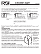
The back, front rail and shelf pieces will need to be cut to the correct size for your
installation. They should each be 3/4” less in length than the overall width of the unit
determined in Step 1. Measure and mark each piece at the determined length and
complete the cut on each piece.
On the newly cut (trimmed) end of the front rail, cut the notches in the front rail to
match the notches on the opposite (untrimmed) end. See Figure 1.
On the newly cut (trimmed) end of the back, drill two holes using a 5/32” drill bit to
match the holes on the opposite (untrimmed) end. See Figure 1.
On the newly cut (trimmed) end of the shelf, cut the notches in the shelf to match the
notches on the opposite (untrimmed) end. See Figure 1.
Continued on the next page
2
3
4
99896 8/07
7/8"
Figure 1
Procedure
3/8"
1/2"
3/4"
Cabinet Width – 3/4"
Front Rail
5/8" Dia. Drill
3/16"
1"
1"
Cabinet Width – 3/4"
Back
Cabinet Width – 3/4"
Shelf
1/2"
3/8"
5
Trimming
1
Installation Instructions Read carefully before you begin installation
THESE INSTRUCTIONS SHOULD NOT BE FAXED OR REPRODUCED ON A DIGITAL COPIER. AMERICAN WOODMARK CORPORATION PROVIDES THESE INSTRUCTIONS ON AN “AS IS” BASIS AND DISCLAIMS ANY AND
ALL LIABILITY FOR ANY INACCURACIES, OMISSIONS OR TYPOGRAPHICAL ERRORS CAUSED BY ANY THIRD PARTY’S EQUIPMENT. When you use these instructions, you are consenting to be bound by the provisions
in this paragraph. These instructions provide an illustrative method for installing American Woodmark Corporation (“AWC”) cabinets and/or accessories. AWC’s instructions are not intended to address every possible
contingency that might be encountered during installation or to endorse the use of any particular tools. AWC HEREBY EXPRESSLY DISCLAIMS ALL LIABILITY FOR ANY CLAIMS FOR INJURY OR DEATH RELATED TO OR
BASED UPON THE USE OF THESE INSTALLATION INSTRUCTIONS AND ANY INSTALLATION INSTRUCTIONS OTHERWISE PROVIDED BY AWC.

Shelf Under Cabinet
2
3
99896 8/07
Apply wood glue in the long groove of a side panel (See Figure 2) and place the shelf in the groove.
Be sure that the groove in the rear of the shelf is flush with the groove in the rear of the side panel.
Secure the shelf with two 1” finishing nails (provided) being careful not to mar the surfaces of the
wood. See Figure 3. Wipe away any excess glue. Repeat this procedure for the opposite end.
Apply wood glue in the short groove of a side panel (see Figure 2) and place the front rail in the groove. Be sure that the notch in the
front rail is flush with the top of the side panel. Secure front rail with one 1” finishing nail (provided), being careful not to mar the
surfaces of the wood. See Figure 3. Wipe away any excess glue. Repeat this procedure for the opposite end.
Hold the back into place and using the holes in the
back as guides, drill two 3/32” pilot holes into each
side panel 5/8” deep.
NOTE: Wrapping a piece of tape around the drill bit
5/8” from the end will aid in drilling to the correct depth.
Remove the back and apply wood glue to the side
panels and shelf grooves that will contact the back.
Position back into place and secure with two #6 x 3/4”
wood screws into each side panel. Using remaining
1” finishing nails, evenly spaced, secure the back to
the shelf. See Figure 3. Wipe away any excess glue.
Upon following directions for suggested drying time for the specific glue used, the unit will be ready for installation.
Wood Glue
Figure 2
Assembly
1
4
Wood
Glue
Figure 3
Front Rail
Side Panel
Flush Ends
1" Finishing Nail
1 Per End
1" Finishing Nail
2 Per End
#6 x 3/4" Wood Screw
4 Required
1" Finishing Nail
Equally Spaced
Side Panel
Flush Ends
Shelf
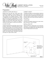
Locate any studs in the area behind where the SUC36T will be installed. Mark the
center of each stud with a pencil. These marks will be needed later in the installation
process.
Hold or clamp the SUC36T in the desired location under the wall cabinet that it is to
be mounted to. Using a 3/32” drill bit, drill two pilot holes approximately 1-1/2” deep
through the above wall cabinet bottom and into the SUC36T. Pilot holes should be
3/8” from the back of the above wall cabinet face frame and approximately 5” from
each side panel of the above wall cabinet. See Figure 4.
NOTE: Be careful not to drill through the top rail of the SUC36T. Wrapping a piece of
tape around the drill bit 1-1/2” from the end will aid in drilling to the correct depth.
Using a 3/32” drill bit, drill a pilot hole approximately 1-1/2” deep through the back of
the SUC36T and into each stud that was marked in Step 1. Re-position the unit into
the desired location. See Figure 5.
Using a 5/32” drill bit, drill two pilot holes 1/2” deep through the bottom of the above
wall cabinet in the same locations that were drilled in Step 2. See Figure 6.
NOTE: Be careful not to drill into the SUC36T. Wrapping a piece of tape around the
drill bit 1/2” from the end will aid in drilling to the correct depth.
Using the #8 x 1-1/2” wood screws, secure the SUC36T to the above wall cabinet
and to the wall. Do not over tighten and strip the threads on the screw.
Installation
1
Pilot Hole
(2 Places)
Figure 4
5" (2 Places)
3/8" (2 Places)
Figure 5
#8 x 1-1/2"
Wood Screw
(2 Places)
Pilot Hole
Wall Cabinet
Wall Cabinet
Bottom
SUC36T
Figure 6
#8 x 1-1/2"
Wood Screw
Wall Stud
Note: Above
Wall Cabinet
not Shown
for Clarity
2
3
4
5
Installation Instructions continued

Instrucciones de instalación Lea con cuidado antes de comenzar la instalación
99896 8/07
Presenta un estante para almacenaje abierto
debajo de la pared de los gabinetes hasta 36”
de ancho.
Contiene
• (1) Panel posterior
• (1) Estante
• (1) Riel frontal
• (2) Paneles laterales–(1) izquierdo y
(1) derecho
• (4) Tornillos para madera Phillips planos
n.º 6 x 3/4”
• (8) Clavos sin cabeza de calibre 1” 17
(clavos de acabado)
Herramientas necesarias
• Taladro
• Brocas para taladro 5/32” y 3/32”
• Adhesivo para madera
• Martillo
• Destornillador Phillips
• Broca avellanadora
• Lápiz
• Cinta Métrica
• Sierra
• Gafas de seguridad
Otros objetos necesarios (no incluidos)
• (4) Tornillos para madera Phillips planos del
n.º 8 x 1-1/2”
Estante debajo del gabinete (SUC36T)
Mida el ancho del marco del gabinete debajo del cual el estante va a estar instalado. Cuando
tenga esta medida, esta va a ser el ancho total de la unidad SUC36T. Si el gabinete tiene 36” de
ancho, consulte la sección de este documento sobre el proceso de ensamblaje. Por el contrario,
pase al paso 2.
La parte posterior, el riel frontal y las partes del estante se deberán cortar a la medida correcta
para ser instalados. Deberán ser 3/4” más pequeños en longitud que el ancho general de la
unidad determinada en el paso 1. Mida y marque cada pieza con la medida específica y complete
el corte de cada pieza.
En el extremo del nuevo corte (con borde) del riel frontal, corte las muescas en el riel frontal para
que estén parejas con las del extremo opuesto (sin reborde). Vea la figura 1.
En el nuevo corte (con reborde) del extremo de la parte posterior, haga dos agujeros usando una
broca de 5/32” para que los agujeros estén parejos a los del extremo opuesto (sin reborde).
Vea la figura 2.
En el nuevo corte (con reborde) del extremo del estante, corte las muescas del estante para que
estén parejas con el extremo opuesto (sin reborde). Vea la figura 1.
Continúa en la siguiente página
2
3
4
7/8"
Figura 1
Procedimiento
3/8"
1/2"
3/4"
Ancho del gabinete – 3/4"
Riel frontal
Taladro de
5/8" de
diámetro
3/16"
1"
1"
Posterior
Estante
1/2"
3/8"
5
Contorno
1
Ancho del gabinete – 3/4"
Ancho del gabinete – 3/4"
ESTAS INSTRUCCIONES NO SE DEBEN ENVIAR POR FAX NI SE DEBEN REPRODUCIR EN UNA COPIADORA DIGITAL. AMERICAN WOODMARK CORPORATION PROPORCIONA ESTAS INSTRUCCIONES “TAL COMO ESTAN”
Y RENUNCIA A CUALQUIER Y A TODA RESPONSABILIDAD POR CUALQUIER FALTA DE PRECISION, OMISION O ERROR TIPOGRAFICO CAUSADO POR EL EQUIPO DE TERCERAS PERSONAS. Al utilizar estas instrucciones,
usted está aceptando estar sujeto a las disposiciones contenidas en este párrafo. Estas instrucciones proporcionan un método ilustrativo para instalar los gabinetes y/ o accesorios de American Woodmark Corporation
(“AWC”). Las instrucciones de AWC no tienen por objeto resolver toda contingencia posible que pudiera presentarse durante la instalación ni recomendar el uso de una herramienta en particular. POR LA PRESENTE,
AWC RENUNCIA EXPRESAMENTE A TODA RESPONSABILIDAD POR CUALQUIER RECLAMACION POR LESIONES O FALLECIMIENTO DERIVADOS DEL USO DE ESTAS INSTRUCCIONES DE INSTALACION Y DE OTRAS
INSTRUCCIONES DE INSTALACION QUE AWC HAYA PROPORCIONADO DE ALGUNA OTRA FORMA.

Instrucciones de instalación continuación
99896 8/07
2
3
Aplique adhesivo para madera en la ranura larga del panel lateral (Vea figura 2) y coloque el estante en la
ranura. Asegúrese de que la ranura de la parte posterior del estante encaja con la ranura del panel lateral.
Asegure el estante con dos clavos de acabado de 1” (incluidos) pero teniendo cuidado en no dañar la superficie
de la madera. Vea la figura 3. Limpie con un trapo cualquier exceso de adhesivo. Repita este procedimiento para
el extremo opuesto.
Aplique el adhesivo en la ranura corta del panel lateral (vea la figura 2) y coloque el riel frontal en la ranura. Asegúrese de que la muesca del riel frontal
encaja con la parte superior del panel lateral. Asegure el riel frontal con uno de los clavos de acabado de 1” (incluido), pero teniendo cuidado de no
dañar la superficie de la madera. Vea figura 3. Limpie con
un trapo cualquier exceso de adhesivo. Repita este
procedimiento para el extremo opuesto.
Mantenga la parte posterior en su lugar y utilizando los
agujeros de la parte posterior como guía, haga dos
agujeros guía de 3/32” en cada panel lateral de una
profundidad de 5/8”. NOTA: Si enrolla un pedazo de cinta
alrededor del extremo de la broca de 5/8” le ayudará a
taladrar la correcta profundidad.
Saque la parte posterior y aplique el adhesivo de madera a
los paneles laterales y a las ranuras de los estantes que
estarán en contacto con la parte posterior. Coloque la parte posterior en su lugar y asegúrela con dos tornillos para madera del n.º 6 x 3/4” en cada
panel lateral. Con el clavo de acabado de 1” que le queda, dejando el mismo espacio, asegure la parte posterior al estante. Vea la figura 3. Limpie con
un trapo cualquier exceso de adhesivo. Después de seguir las instrucciones para el tiempo
recomendado de secado para el adhesivo utilizado, la unidad estará lista para ser instalada.
Figura 2
Ensamblaje
1
4
Adhesivo
para
madera
Figura 3
Riel frontal
Panel lateral
Extremos del
encaje
Clavo de 1" de acabado
1 para cada extremo
Clavo de 1" de acabado
2 para cada extremo
n.º 6 x 3/4" Tornillos para
madera 4 necesarios
Clavo de 1" de
acabado
espaciados a la
misma distancia
Panel lateral
Extremos del encaje
Estante
Localice los montantes en la parte trasera donde la SUC36T va a ser instalada. Marque el centro
de cada montante con un lápiz. Estas marcas se van a necesitar posteriormente en el proceso de
instalación.
Aguante o ponga una abrazadera en la SUC36T en el lugar deseado debajo de la pared del
gabinete en la que se va a montar. Usando una broca de 3/32”, haga dos agujeros guía
aproximadamente de 1-1/2” de profundidad a través de la base de la pared superior del
gabinete y en la SU36T. Los agujeros guía deben estar a 3/8" de distancia del marco frontal de
la pared del gabinete y a 5” aproximadamente de cada panel lateral de la pared superior del
gabinete. Vea figura 4. NOTA: Asegúrese que no taladra a través del riel superior de la SUC36T.
Si enrolla un pedazo de cinta alrededor del extremo de la broca de 1-1/2” le ayudará a taladrar
la correcta profundidad.
Use una broca de 3/32” para taladrar un agujero guía aproximadamente de 1-1/2” de
profundidad a través de la parte posterior de la SUC36T y en cada uno de los montantes que se
habían marcado en el paso 1. Vuelva a poner la unidad en el lugar deseado. Vea la figura 5.
Use una broca de 5/32”, taladre dos agujeros guía de 1/2” de profundidad a través de la base
de la pared superior del gabinete en los mismos lugares donde se taladraron en el paso 2. Vea
la figura 6. NOTA: Asegúrese que no taladre la SUC36T. Si enrolla un pedazo de cinta alrededor
del extremo de la broca de 1/2” le ayudará a taladrar la correcta profundidad.
Use los tornillos del n.º 8 x 1-1/2”, asegure la unidad del SUC36T a la pared superior del
gabinete y a la pared. No los apriete demasiado ni corte las roscas de los tornillos.
Instalación
1
Agujero guía
(2 lugares)
Figura 4
5" (2 lugares)
3/8" (2 lugares)
Figura 5
n.º 8 x 1-1/2"
Tornillos para madera
(2 lugares)
Agujero guía
Gabinete de
pared
Base de la
pared del
gabinete
SUC36T
Figura 6
n.º 8 x 1-1/2"
Tornillos para
madera
Montante de la
pared
Nota: Los
gabinetes de
arriba de
pared no se
muestran por
su claridad
2
3
4
5
Estante debajo del gabinete
Adhesivo para
madera
/