Page is loading ...

Congratulations!
You have purchased the finest radiant heater available for the heating of livestock
in agricultural animal confinement buildings.
Your new L.B. White radiant heater incorporates the benefits from the most
experienced manufacturer of heating products using state-of-the-art technology.
We, at L.B. White, thank you for your confidence in our products and welcome any
suggestions or comments you may have...call us toll free at 1-800-345-7200.
Owner’s Manual and Instructions
Spark Ignition Infraconic
Agricultural Building Radiant Heaters
ATTENTION ALL USERS
This heater has been tested and evaluated by L.B. White Co., Inc. as a direct gas-fired
radiant heater with intended use for the heating of livestock in agricultural animal
confinement buildings. If you are considering using this product for any application other
than its intended use, then please contact your fuel gas supplier, or the L.B. White Co., Inc.
150-22721-A
MODELS OUTPUT (Btuh) FUEL
I17 17,100
I34 34,200
L.P. Vapor
Withdrawal
or Natural Gas


WARNING
Fire and Explosion Hazard
■Not for home or recreational vehicle use.
■Installation of this brooder in a home or
recreational vehicle may result in a fire or
explosion.
■Fire or explosions can cause property
damage or loss of life.
FOR YOUR SAFETY
If you smell gas:
1. Open windows.
2. Don't touch electrical switches.
3. Extinguish any open flame.
4. Immediately call your gas supplier.
FOR YOUR SAFETY
Do not store or use gasoline or other
flammable vapors and liquids in the vicinity of
this or any other appliance.
WARNING
Fire and Explosion Hazard
■Keep solid combustibles a safe distance
away from the brooder.
■Solid combustibles include wood or paper
products, feathers, straw, and dust.
■Do not use the brooder in spaces which
contain or may contain volatile or airborne
combustibles.
■Volatile or airborne combustibles include
gasoline, solvents, paint thinner, dust
particles or unknown chemicals.
■Failure to follow these instructions may
result in a fire or explosion.
■Fire or explosions can lead to property
damage, personal injury or loss of life.
GENERAL HAZARD WARNING
■Failure to comply with the precautions and instructions provided with this brooder, can result
in:
— Death
— Serious bodily injury or burns
— Property damage or loss from fire or explosion
— Asphyxiation due to lack of adequate air supply or carbon monoxide poisoning
— Electrical shock
■Read this Owner’s Manual before installing or using this product.
■Only properly-trained service people should repair or install this brooder.
■Save this Owner’s Manual for future use and reference.
■Owner’s Manuals and replacement labels are available at no charge. For assistance, contact
L.B. White at 800-345-7200.
WARNING
■Proper gas supply pressure must be provided to the inlet of the brooder.
■Refer to rating plate for proper gas supply pressure.
■Gas pressure in excess of the maximum inlet pressure specified at the brooder inlet can cause
fires or explosions.
■Fires or explosions can lead to serious injury, death, building damage or loss of livestock.
■Gas pressure below the minimum inlet pressure specified at the brooder inlet may cause
improper combustion.
■Improper combustion can lead to asphyxiation or carbon monoxide poisoning and therefore
serious injury or death to humans and livestock.
2

This owner's manual includes all options and accessories
commonly used on or with this heater. However, depending
on the configuration purchased, some options and
accessories may not be included.
When calling for technical service assistance, or for other
specific information, always have the model number and
serial number available.
This manual will instruct you in the operation and care of
your radiant heater. Have your qualified installer review this
manual with you so that you fully understand the heater and
how it functions.
The gas supply line installation, and the repair, installation
and servicing of the heater requires continuing expert
training and knowledge of gas heaters and should not be
attempted by anyone who is not so qualified. See page 6
for definition of the necessary qualifications.
Contact your local L. B. White distributor or the L. B. White
Co., Inc. for assistance, or if you have any questions about
the use of the heater or its application.
The L. B. White Co., Inc. has a policy of continuous product
improvement. It reserves the right to change specifications
and design without notice.
SECTION PAGE
General Information . . . . . . . . . . . . . . . . . . . . . . . . . . . . . . . . . . . . . . . . . . . . . . . . . . . . . . . . . . . . . . . . . . .3
Heater Specifications . . . . . . . . . . . . . . . . . . . . . . . . . . . . . . . . . . . . . . . . . . . . . . . . . . . . . . . . . . . . . . . . . .4
Safety Precautions . . . . . . . . . . . . . . . . . . . . . . . . . . . . . . . . . . . . . . . . . . . . . . . . . . . . . . . . . . . . . . . . . . . .5
Installation Instructions
General . . . . . . . . . . . . . . . . . . . . . . . . . . . . . . . . . . . . . . . . . . . . . . . . . . . . . . . . . . . . . . . . . . . . . . . . .7
Gas Train Assembly . . . . . . . . . . . . . . . . . . . . . . . . . . . . . . . . . . . . . . . . . . . . . . . . . . . . . . . . . . . . . . . .9
Filter Kit Instructions
Installing Filter . . . . . . . . . . . . . . . . . . . . . . . . . . . . . . . . . . . . . . . . . . . . . . . . . . . . . . . . . . . . . . . . . . . .9
Cleaning the Filter . . . . . . . . . . . . . . . . . . . . . . . . . . . . . . . . . . . . . . . . . . . . . . . . . . . . . . . . . . . . . . . .10
Start-Up Instructions . . . . . . . . . . . . . . . . . . . . . . . . . . . . . . . . . . . . . . . . . . . . . . . . . . . . . . . . . . . . . . . . .11
Shut-Down Instructions . . . . . . . . . . . . . . . . . . . . . . . . . . . . . . . . . . . . . . . . . . . . . . . . . . . . . . . . . . . . . . .11
Cleaning Instructions . . . . . . . . . . . . . . . . . . . . . . . . . . . . . . . . . . . . . . . . . . . . . . . . . . . . . . . . . . . . . . . . .12
Maintenance Instructions . . . . . . . . . . . . . . . . . . . . . . . . . . . . . . . . . . . . . . . . . . . . . . . . . . . . . . . . . . . . .13
Service Instructions
General . . . . . . . . . . . . . . . . . . . . . . . . . . . . . . . . . . . . . . . . . . . . . . . . . . . . . . . . . . . . . . . . . . . . . . . .13
On/Off Switch . . . . . . . . . . . . . . . . . . . . . . . . . . . . . . . . . . . . . . . . . . . . . . . . . . . . . . . . . . . . . . . . . . .14
Ignition Module . . . . . . . . . . . . . . . . . . . . . . . . . . . . . . . . . . . . . . . . . . . . . . . . . . . . . . . . . . . . . . . . . .14
Burner Orifice . . . . . . . . . . . . . . . . . . . . . . . . . . . . . . . . . . . . . . . . . . . . . . . . . . . . . . . . . . . . . . . . . . .14
High Voltage Ignition Lead . . . . . . . . . . . . . . . . . . . . . . . . . . . . . . . . . . . . . . . . . . . . . . . . . . . . . . . . .15
Igniter/Flame Sensor . . . . . . . . . . . . . . . . . . . . . . . . . . . . . . . . . . . . . . . . . . . . . . . . . . . . . . . . . . . . .16
Gas Control Valve . . . . . . . . . . . . . . . . . . . . . . . . . . . . . . . . . . . . . . . . . . . . . . . . . . . . . . . . . . . . . . . .17
High Limit Switch . . . . . . . . . . . . . . . . . . . . . . . . . . . . . . . . . . . . . . . . . . . . . . . . . . . . . . . . . . . . . . . . .17
Gas Pressure Checks . . . . . . . . . . . . . . . . . . . . . . . . . . . . . . . . . . . . . . . . . . . . . . . . . . . . . . . . . . . . .18
Troubleshooting Guide . . . . . . . . . . . . . . . . . . . . . . . . . . . . . . . . . . . . . . . . . . . . . . . . . . . . . . . . . . . . . . . .19
Electrical Connection and Ladder Diagram . . . . . . . . . . . . . . . . . . . . . . . . . . . . . . . . . . . . . . . . . . . . . . .23
Heater Component Function . . . . . . . . . . . . . . . . . . . . . . . . . . . . . . . . . . . . . . . . . . . . . . . . . . . . . . . . . . .24
Parts Identification
Parts Schematic . . . . . . . . . . . . . . . . . . . . . . . . . . . . . . . . . . . . . . . . . . . . . . . . . . . . . . . . . . . . . . . . .25
Parts List . . . . . . . . . . . . . . . . . . . . . . . . . . . . . . . . . . . . . . . . . . . . . . . . . . . . . . . . . . . . . . . . . . . . . . .26
Warranty Policy . . . . . . . . . . . . . . . . . . . . . . . . . . . . . . . . . . . . . . . . . . . . . . . . . . . . . . . . . . . . . . . . . . . . . .27
Replacement Parts and Service . . . . . . . . . . . . . . . . . . . . . . . . . . . . . . . . . . . . . . . . . . . . . . . . . . . . . . . .27
Table of Contents
General Information
3

I17 I34
Maximum Input (Btuh) 17,100 34,200
Ventilation Air to Support Combustion
5 psig
5 psig
5 psig
2.5 psig
5 psig
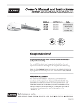
“A” 16 7/8 in. 26 3/8 in.
“B” 17 in. 20 1/4 in.
“C” 8 3/4 in. 10 3/8 in.
Net Weight 8 lbs. 10 oz. 15 lbs. 8 oz.
L.P. GAS .80 lbs./hr. 1.58 lbs./hr.
NATURAL GAS
120/60/1
0.5
CHICKENS 1250 - 2000 2500 - 3800
TURKEYS 350 - 500 800 - 950
SWINE 125 300
CHICKENS 5 - 6 ft. 6 - 7 ft.
TURKEYS 4 ft. 4.5 ft.
SWINE 4 - 5 ft.
TOP OF HOOD TO CEILING 3 ft.
POINT OF COMBUSTION
CONE TO FLOOR
SIDES 3 ft.
POULTRY
SWINE
4
SPECIFICATIONS
Radiant Heater Specifications
FIG. 1
Heater Dimensions
(See Fig. 1)
Fuel Consumption Per Hour
Animal Coverage Per Heater (1)
Minimum Safe Clearances to
Combustible Materials
Recommended Height Installation
For Livestock From Point of
Combustion Cone to Floor
200 CFM
17.1 CFH
3.5 ft. 4.5 ft.
34.2 CFH
400 CFM
N/A - Not applicable.
(1) There are other factors that will affect the quantity of animals
each heater can cover. These include building ventilation and
control systems, building insulation, building size and population
density, etc. Consult your L. B. White dealer or call L. B. White for
specific recommendations for your application.
(2) This is typical sensor placement range. The size and type of
livestock being grown, heater spacing and height, etc. will dictate
sensor location. Care should always be taken to ensure that the
sensor is sufficiently high as to not be damaged by the animal
during operation.
"B"
"A"
"C"
Electrical Supply (Volts/HZ/Phase)
Amp Draw
Animal Occupied Zone Temperature
Control Sensor Location (2)
Inlet Gas Supply Pressure at the Heater
MAX.
MIN.
MAX.
MIN.
VERTICAL FROM FLOOR 6-12 in.
HORIZONTAL FROM BROODER 8-12 ft.
VERTICAL FROM FLOOR Above Animal Height
HORIZONTAL FROM BROODER 4-8 ft.
MMooddeell
FULL OUTPUT
(On/Off
Version)
ZONE
CONTROLLED
(Dual Solenoid
Version)
Burner Manifold Pressure at Maximum Pressure

LP ggas aand nnatural ggas hhave mman-mmade oodorants aadded sspecifically ffor ddetection oof ffuel ggas lleaks.
If aa ggas lleak ooccurs, yyou sshould bbe aable tto ssmell tthe ffuel ggas.
THAT’S YYOUR SSIGNAL TTO GGO IINTO IIMMEDIATE AACTION!
■Do not take any action that could ignite the fuel gas. Do
not operate any electrical switches. Do not pull any
power supply or extension cords. Do not light matches
or any other source of flame. Do not use your
telephone.
■Get everyone out of the building and away from the area
immediately.
■Close all propane (LP) gas tank or cylinder fuel supply
valves, or the main fuel supply valve located at the
meter if you use natural gas.
■Propane (LP) gas is heavier than air and may settle in
low areas. When you have reason to suspect a propane
leak, keep out of all low areas.
■Natural gas is lighter than air and can collect around
rafters or ceilings.
■Use your neighbor’s phone and call your fuel gas
supplier and your fire department. Do not re-enter the
building or area.
■Stay out of the building and away from the area until
declared safe by the firefighters and your fuel gas
supplier.
■FINALLY, let the fuel gas service person and the
firefighters check for escaped gas. Have them air out
the building and area before you return. Properly
trained service people must repair the leak, check for
further leakages, and then relight the heater for you.
WARNING
■Do not use this radiant heater for heating human living
quarters.
■Do not use in unventilated areas.
■The flow of combustion and ventilation air must not be
obstructed.
■Proper ventilation air must be provided to support the
combustion air requirements of the heater being used.
■Refer to the specification section of the Owner’s
Manual, heater’s dataplate, or contact the
L.B. White Company to determine combustion air
ventilation requirements of the heater.
■Lack of proper ventilation air will lead to improper
combustion.
■Improper combustion can lead to carbon monoxide
poisoning in humans leading to serious injury or death.
Symptoms of carbon monoxide poisoning can include
headaches, dizziness and difficulty in breathing.
■Symptoms of improper combustion affecting livestock
can be disease, lower feed conversion, or death.
Asphyxiation Hazard
■Some ppeople ccannot ssmell wwell. SSome ppeople ccannot
smell tthe oodor oof tthe mman-mmade cchemical aadded tto
propane ((LP) oor nnatural ggas. YYou mmust ddetermine iif yyou
can ssmell tthe oodorant iin tthese ffuel ggases.
■Learn to recognize the odor of propane (LP) gas and
natural gas. Local propane (LP) gas dealers and your
local natural gas supplier (utility) will be more than
happy to give you a “scratch and sniff” pamphlet. Use it
to become familiar with the fuel gas odor.
■Smoking can decrease your ability to smell. Being
around an odor for a period of time can affect your
sensitivity to that particular odor. Odors present in
animal confinement buildings can mask fuel gas odor.
■The oodorant iin ppropane ((LP) ggas aand nnatural ggas iis
colorless aand tthe iintensity oof iits oodor ccan ffade uunder
some ccircumstances.
■If there is an underground leak, the movement of gas
through the soil can filter the odorant.
■Propane (LP) gas odor may differ in intensity at different
levels. Since propane (LP) gas is heavier than air, there
may be more odor at lower levels.
■Always bbe ssensitive tto tthe sslightest ggas oodor. If you
continue to detect any gas odor, no matter how small,
treat it as a serious leak. Immediately go into action as
discussed previously.
Safety Precautions
FUEL GAS ODOR
ODOR FADING -- NO ODOR DETECTED
ATTENTION -- CRITICAL POINTS TO REMEMBER!
■Propane (LP) gas and natural gas have a distinctive
odor. Learn to recognize these odors. (Reference “Fuel
Gas Odor” and “Odor Fading” sections above.
■
If you have not been properly trained in repair and service
of propane (LP) gas and natural gas fueled heaters, then
do not attempt to light the heater, perform service or
repairs, or make any adjustments to the heater on a
propane (LP) gas or natural gas fuel system.
■Even if you are not properly trained in the service and
repair of radiant heaters, ALWAYS be consciously aware
of the odors of propane (LP) gas and natural gas.
■A periodic “sniff test” around the heater or at the
heater’s joints; i.e. hose, connections, etc., is a good
safety practice under any conditions. If you smell even
a small amount of gas, CONTACT YOUR FUEL GAS
SUPPLIER IMMEDIATELY. DO NOT WAIT!
5

1. Do not attempt to install, repair or service this heater
or the gas supply line unless you have continuing
expert training and knowledge of gas heaters.
Qualifications for service and installation of this
equipment are as follows:
QUALIFICATIONS FOR
SERVICING AND INSTALLATION:
a. To be a qualified gas heater service person, you
must have been trained in gas-fired heater
servicing, repair and also have sufficient
experience to allow you to troubleshoot, replace
defective parts, and test heaters in order to get
them into a continuing safe and normal operation
condition. You must completely familiarize
yourself with each model heater by reading and
complying with the safety instructions, labels,
owner’s manual, etc. that is provided with each
heater.
b. To be a qualified gas installation person, you must
have sufficient training and experience to handle
all aspects of installing, repairing and altering gas
lines, including selecting and installing the proper
equipment, and selecting proper pipe size to be
used. This must be done in accordance with all
local, state and national codes as well as the
manufacturer’s requirements.
2. All installations or applications of L. B. White Co.,
Inc.’s radiant heater and associated zone control
panel should meet the requirements of local, state
and national L.P. gas and natural gas, electrical and
safety codes. Your gas supplier, local licensed
electrician, local fire department and government
agencies can help you determine these requirements.
In the absence of local codes, comply with the
following:
-- ANSI/NFPA 58, latest edition, Standard for
Storage and Handling of Liquefied Petroleum
Gas and/or
-- ANSI Z223.1/NFPA 54, National Fuel Gas
Code
-- ANSI/NFPA 70, National Electrical Code.
3. If at any time you notice something unusual about the
operation of your heater such as gas odor,
overheating, flames other than in the combustion
cone area, etc., evacuate the area immediately and
call your fire department and your gas service
agency. Get assurances from the fire department
that the area is free of gas before you attempt to
relight the heater.
4. The components on the heater that call for hand
operation should work with hand pressure only. If
more force is required, have a qualified gas heater
service agency replace the complete part. Do not
attempt to repair.
5. This heater is intended for the heating of livestock in
agricultural animal confinement buildings only. The
heater shall only be mounted inside the animal
confinement building. It shall not be used for outside
heating applications.
6. Do not locate fuel gas containers or fuel supply hoses
anywhere within the heating zone of the heater.
7. Do not block the air intake, burner venturi tube or
burner cone area. Doing so may cause improper
combustion or damage to the heater components,
leading to property damage or animal loss.
8. Do not move, handle, or service the heater while in
operation or connected to fuel supply.
9. The hose assembly providing fuel to the heater must
be inspected on a regular basis. This should be done
at least once a year, or when the building is cleaned
out. If it is evident there is excessive abrasion or
wear, or if the hose is cut, it must be replaced prior to
heater being put into operation. The hose assembly
shall be protected from animals, building materials,
and contact with hot surfaces during use. The hose
assembly shall be that specified by the manufacturer.
See parts list.
10. Check for gas leaks and proper function upon
installation, before building repopulation and when
relocating.
11. If the gas flow is interrupted and the burner flame is
extinguished, immediately shut off the gas. Do not
relight the heater until you are sure that all of the gas
that may have accumulated through the brooder has
cleared away. Do not relight the heater until at least
five minutes have passed.
12. If the heater is to be relocated, make sure that all gas
connections are capped and the gas supply is shut
off. All connection points must be leak checked after
disconnection and after reconnection.
13. The grower shall inspect the heater before building
repopulation. Such inspection should consist of, but
is not limited to, the following points of action:
6
WARNING
Burn HHazard
Can ccause pproperty ddamage, ssevere iinjury oor ddeath.
■The heater’s combustion cones and canopy are
extremely hot during operation and shortly after
shutting down.
■Always be aware of your proximity to the heater and
avoid contact with its hot surfaces during or shortly
after operation.
■Failure to follow this warning can result in burns
leading to severe personal injury.
Safety Precautions

1. Read all safety precautions and follow L. B. White
recommendations when installing this heater. If
during the installation or relocating of the heater, you
suspect that a part is damaged or defective, call a
qualified service agency for repair or replacement.
2. On initial installation and before use, position the
brooder properly regarding clearance to combustible
materials and ground clearance to protect the
brooder from livestock. Hang the brooder with the
control end 1 to 5 degrees down from horizontal.
This is necessary to protect the filter and control
enclosure from heat damage as well as providing
proper venting to ensure good combustion. Refer to
the specification table on page 4 as well as Figure 2
for installation information for proper hanging and
clearances.
3. Position the gas hose outside of the hot zone directly
above the heater. Position the gas hose to avoid any
opportunity for contact with the hot canopy surface of
the heater. Refer to Fig. 2.
4. Insure that all accessories that ship with the heater
have been removed from inside of heater’s shipping
container and installed. This pertains to gas hose,
regulators, etc.
5. The heater’s gas regulator (with pressure relief valve)
should be installed outside of building. Typically any
regulators inside the buildings must be properly
vented to the outside. However, local, state and
national codes always apply to regulator installation.
6. It is extremely important that any regulator outside
the building be protected against the weather,
particularly ice formation. Ice formation can lead to
overpressurization of the regulator and subsequent
gas leaks. See codes covering proper protection.
7. Always use pipe joint compound that is resistant to
liquefied petroleum gas and natural gas.
8. Check all connections for gas leaks using approved
gas leak detectors. Gas leak testing is performed as
follows:
-- Check all pipe connections, hose connections,
fittings and adapters upstream of the gas
control with approved gas leak detectors.
-- In the event a gas leak is detected, check the
components involved for cleanliness and
proper application of pipe compound before
further tightening.
-- Furthermore tighten the gas connections as
necessary to stop the leak.
-- After all connections are checked and any
leaks are stopped, turn on the main burner.
-- Stand clear while the main burner ignites to
prevent injury caused from hidden leaks that
could cause flashback.
-- With the main burner in operation, check all
connections, hose connections, fittings and
joints as well as the gas control valve inlet and
outlet connections with approved gas leak
detectors.
7
Installation Instructions
GENERAL
-- Insure proper clearance of heater to nearest
combustible materials.
-- Check for general cleanliness. Clean if necessary.
-- Check for tightness of the gas hose connections.
14. A qualified service person shall inspect the heater
and its gas train on at least an annual basis. This
should consist of, but is not limited to, the following
points of action:
-- Start-up and shut down of the heaters and zone
control panel to test for proper operation.
-- Leak check of all pipe joints and hose connections.
-- Thorough cleaning of the exterior of the heater, its
inlet venturi, combustion cones and filter (if
applicable).
-- Thorough inspection of the heater’s component
parts for corrosion, stripped threads, etc. with
subsequent parts replacement as necessary.
-- Gas pressure checks.
15. Turn off the gas supply when the heater is not in use.
WARNING
Fire oor eexplosion hhazard.
Can ccause pproperty ddamage, ssevere iinjury oor ddeath.
To avoid dangerous accumulation of fuel gas, turn off
the gas supply at the heater service valve before
starting installation, and perform gas leak test after
completion of installation.
WARNING
Fire aand EExplosion HHazard
■Do not use open flame (matches, torches, candles,
etc.) in checking for gas leaks.
■Use only approved leak detectors.
■Failure to follow this warning can lead to fires or
explosions.
■Fires or explosions can lead to property damage,
personal injury or loss of life.

INSTALLATION LAYOUT
FOR SAFE CLEARANCES
I17 & I34 - 3 FT. MINIMUM
BROODER TOP TO CEILING
POSITION THE GAS HOSE AND ELECTRICAL POWER CORD
OUTSIDE OF THE HOT ZONE DIRECTLY ABOVE THE HEATER.
POSITION THE GAS HOSE AND POWER CORD TO AVOID
ANY OPPORTUNITY FOR CONTACT WITH THE HOT CANOPY
SURFACE OF THE HEATER.
MINIMUM 3 FT. CLEARANCE
TO COMBUSTIBLES
FLOOR
I17 - 3.5 FT. MINIMUM
I34 - 4.5 FT. MINIMUM
POINT OF COMBUSTION
CONE TO FLOOR
HANG THE HEATER WITH THE
CONTROL END 1 TO 5 DEGREES DOWN
FROM HORIZONTAL (SEE BELOW)
CONTROL PANEL
GAS PIPING
-- If a leak is detected, check the components
involved for cleanliness in the thread areas and
proper application of pipe compound before
further tightening.
-- Tighten the gas connection as necessary to
stop the leak.
-- If necessary, replace the parts or components
involved if the leak cannot be stopped.
-- Ensure all gas leaks have been identified and
repaired before proceeding.
9. A qualified service agency must check for proper
operating gas pressures upon installation of the
heaters.
10. It is extremely important to use the proper gas supply
line to assure proper functioning of the heaters.
Typically, 1/2 in. ID black iron pipe is used to convey
the gas to the heaters. However, always consult your
fuel gas supplier, or the L. B. White Co., Inc. for proper
line sizing and installation.
11. Infraconic heaters require a regulated gas supply to
the gas inlet of the product. Exceeding the gas inlet
pressure rating can result in poor performance and
unreliable operation. Refer to page 4 of this manual
for information on gas pressures relating to specific
models.
12. The heater is designed for either L.P. vapor withdrawal
or natural gas, depending on model number. Do not
use this heater in an LPG liquid withdrawal
system. Do not permit LPG in liquid form to enter the
heater at any time.
13. The corrosive atmosphere present in animal
confinement buildings can cause component failure or
heater malfunction. The heater should be periodically
inspected and cleaned in accordance with the
Maintenance and Cleaning Instructions in this manual.
Make sure that livestock is protected by a back up
alarm system that limits high and low temperatures
and also activates appropriate alarms.
14. Take time to understand how to operate and maintain
the heater using the owner’s manual. Make sure you
know how to shut off the gas supply to the building
and to the individual heaters. Contact your gas
supplier if you have any questions.
15. Any defects found in performing any of the service
procedures must be eliminated and defective parts
replaced immediately. Retest the heater before
placing it back into service.
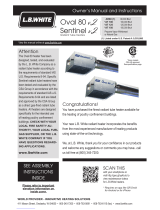
FIG. 2
AATTTTEENNTTIIOONN
■Model I17 heaters utilize an
integral chain hanging bracket
located on the heater’s venturi
tube. Model I34 heaters use
chain hanging clips.
■Regardless of hanging system,
the installer must make sure
that the heater is installed so
control end of heater is
positioned 1º to 5º down from
horizontal after gas supply hose
is attached.
■Repositioning of factory
installed key ring into hanging
bracket (for I17) or adjustment
of chain for I34 may be
required.
■Refer to following illustrations.
CONTROL END MUST BE
1 TO 5 DOWN FROM
HORIZONTAL
THIS NOT THIS
CONTROL END
OF HEATER
THIS NOT THIS
HANGING
BRACKET
CONTROL END MUST BE
1 TO 5 DOWN FROM
HORIZONTAL
CONTROL END
OF HEATER
MMOODDEELL II1177MMOODDEELL II3344
8

1. Thread the bushing into one end of manual shut off
valve. Use pipe thread compound at this connection
and tighten securely.
2. Thread the rigid end of the hose into the bushing.
Use pipe thread compound at this connection and
tighten securely.
3. Thread other end of gas hose with fitting to the
adapter at inlet of gas control valve on heater.
Tighten securely.
4. Connect the gas supply to inlet of manual gas shut off
as required by local codes.
GAS TRAIN ASSEMBLY
9
BUSHING
TO ZONE CONTROL
PANEL PLUMBING
VALVE, SHUT-OFF
HOSE
GAS CONTROL
ADAPTER
HEATER
FIG. 3
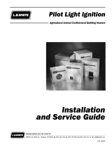
Filter Instructions
1. Position the filter sleeve onto the injector body.
Fasten the sleeve to the body by pushing the slots of
the sleeve onto the tabs of the body. Rotate the
sleeve so it locks into place on the injector body. See
Fig. 4.
2. Expand the elastic on the filter and slide the filter over
the sleeve. Make sure the elastic of the filter is
covering the top of the sleeve and that the seam of
the filter is perpendicular to the canopy edge of the
heater. See Fig. 4. Filter sleeve holes will not be
exposed when the filter is properly installed.
3. After installation, make sure that the filter does not
sag or touch the canopy of the heater.
4. The operating position of the heater must allow for a
tilt of the canopy of between 1° (min.) and 5° (max.)
from the filter end of the heater. The tilt angle is
necessary to allow proper venting of combustion by-
products from the heater as well as minimize
convective and radiant heat to the filter element.
INSTALLING FILTER
ATTENTION
MODEL II17 HHEATERS
■There will be a snug fit of the filter against the control
box after filter installation.
TO GAS
SUPPLY
ATTENTION
■The control end of the heater must be down 1 to 5
from horizontal. Refer to Fig. 2 on Page 8 for proper
hanging and installation information.

CLEANING THE FILTER
1. During EEach FFlock — Remove the filter and shake out
the dust. Reinstall the filter according to previous
instructions.
2. After EEach FFlock — If necessary, remove the filter and
use compressed air and/or water to clean the filter.
Make sure to squeeze out any excess water from the
filter before reinstalling the filter back onto the filter
sleeve. DO NOT USE A PRESSURE WASHER TO CLEAN
THE FILTER. DO NOT WASH IN A WASHING MACHINE.
High pressure, either water or air, can tear the filter
material. Use standard faucet pressure only. Clean the
venturi tube and cones if necessary using pressurized
air and/or water. Refer to the cleaning instruction
guidelines in this Owner's Manual. Let the heater and
filter dry completely before lighting.
CAUTION
■Never allow the filter to become fully clogged with dust
and dirt.
■A dust choked filter will restrict the combustion air,
causing improper combustion.
■Signs of improper combustion include: backflashing
of flame into the venturi tube, yellowing of the flame
within the burner cone, presence of blue and/or
yellow flames outside of the outer cone or carbon
sooting on the underside of the canopy.
■At first signs of any of these conditions, clean the
filter.
ATTENTION
■Do not squeeze or tap the filter while the heater is in
operation.
■Doing so will allow dust to be ingested within the
venturl tube and cones.
■Shut the heater off and remove filter in its entirety
and shake out dust
10
I17 FILTER KIT - PART #500-20427
I34 FILTER KIT - PART #500-20428
1 DEGREE MINIMUM
TO
5 DEGREES MAXIMUM
SEAM
INJECTOR BODY TABS
FILTER SLEEVE PART #
(I17) 400-20321
(I34) 400-20421
DUST FILTER PART #
(I17) 550-20451
(I34) 550-20452
FIG. 4
(Frequency of cleaning will depend upon livestock being raised and overall condition of the building.)
PA RT #
(I17) 130-20361
(I34) 130-20429

ON/OFF SWITCH
ON
11
The building’s environmental temperature control system
will shut the heater down after proper temperature has been
achieved.
If heater is to be shut down for cleaning, maintenance or
repair, follow steps 1-4.
1. Shut off all gas supply valves to the heaters.
2. Allow heaters to burn off fuel gas remaining in the
gas supply line.
3. Position the ON/OFF switch to OFF.
4. Disconnect the heater from its electrical supply.
Shut-Down Instructions
Follow steps 1-5 on initial start up after heater installation
by a qualified gas heater service person. For normal
startup, simply turn the building thermostat above room
temperature.
1. Connect the heater to an approved electrical supply
and building’s temperature control system.
2. Open all gas supply valves to the heater and check
for gas leaks at all connections using approved leak
detectors.
3. Energize the building’s temperature control system to
provide power to the heater.
4. Position the ON/OFF switch on the heater’s control
box to ON. See Fig. 5. Refer to label near switch.
The igniter will spark and ignition will occur.
5. Set the building’s temperature control to desired
temperature.
This heater includes a spark ignition control module for
purposes of controlling the timing of the ignition process of
the heater as well as monitoring the safety functions. The
control module is located in a control box at the gas inlet
end of the heater. On a call for heat, the igniter will spark
and the gas control valve will open shortly afterward. The
igniter will continue to spark for approximately 10 seconds.
Flame sense, as monitored by the ignition control, will keep
the gas valve open and main burner in operation until
proper temperature is achieved.
The ignition control module will make up to 3 trials for
ignition. There will be a 15 second time span between each
ignition trial. If ignition is not achieved after the third trial, a
15 minute wait period will occur. After the 15 minute time
span has elapsed, the heater will make three more trials for
ignition. This process will continue as long as there is a call
for heat from the building’s temperature control system.
FIG. 5
Start-Up Instructions
ATTENTION
■It is normal for air to be trapped in the gas line on
new installations.
■The heater may attempt more than one ignition trial
before air is purged from the line and ignition occurs.

AIR NOZZLE
12
It is important to clean the heater on a regular basis to
maintain proper combustion and to eliminate future
problems.
The frequency of cleaning will vary depending upon
livestock being raised and overall ventilation of the building.
CLEANING WITH BACKPACK BLOWERS
AND HEATER BLOWER
Blower Part No. 130-21170
For general cleaning when the heaters do not have heavy
accumulations of dust or dirt, use either a backpack type of
blower or the heater blower.
Follow the same procedures for cleaning as listed for
“Cleaning with Compressed Air”.
If the dust and dirt cannot be removed effectively using the
backpack blower or heater blower, then clean the heater
using either the “Compressed Air” or “Water Cleaning”
methods.
CLEANING WITH COMPRESSED AIR
1. Turn off the gas supply to the heater and let the
heater cool down until you can no longer feel heat
coming from the heater canopy or combustion cones.
2. Using a soft bristle brush, brush off all exterior
surfaces of the heater. Pay particular attention to the
air inlet hole on the injector body.
3. Turn on the compressed air and point the nozzle
directly at the combustion cones, working your way
around entire surface of cone assembly. This
procedure may take about a minute or slightly longer
depending on amount of dust or dirt on combustion
cones. See Fig. 6.
4. Shoot compressed air through air inlet opening in the
venturi tube to blow back out any loosened dust
through combustion cones.
5. Repeat Steps 3 and 4 until the cones and the venturi
tube are no longer emitting dust.
6. Visually inspect the cones and venturi tube to make
sure these areas are clean.
7. Return the heater to its normal hanging position.
8. Relight the heater.
FIG. 6
Cleaning Instructions
ATTENTION
Combustion problems associated with lack of cleaning
typically are:
■Sooting on inside of canopy.
■Burner flame appearing beyond outer cone.

Service Instructions
1. Disconnect the gas supply to heater before
attempting to service unless it is necessary to have it
connected for your service procedure. Use special
care to avoid being burned by hot surfaces or make
sure the heater is cool to touch before servicing.
2. Do not attempt to repair any part that comes in
contact with the gas such as the hose and
combustion cones, etc. Replace them.
3. Do not attempt to disassemble or repair any of the
following parts: valves of any kind, regulators,
thermostats, electronic devices, switches, safety
devices, hose assemblies, etc. Replace them.
4. After any repairs are made, always restart the heater
to make sure it operates properly. Refer to “Start Up
Instructions” within this Owner’s Manual.
5. For help in servicing this heater see the Trouble-
shooting Guide within this Owner’s Manual or call the
manufacturer. Some of the manufacturers of
components parts will provide additional information
on their products. Consult these materials if
applicable.
NOTE: The sshroud aand ccombustion ccones ttypically ddo nnot
require rremoval ffrom tthe hheater aassembly. OOther
basic ccomponents oof tthe hheater aare eeasily sserviced
by ffollowing tthese pprocedures.
GENERAL
13
1. Have your gas supplier check all gas piping annually
for leaks or restrictions in gas lines. Also, at this time
have your gas supplier clean out the sediment trap on
the zone control panel of any debris that may have
accumulated.
2. The aappliance aarea sshall bbe kkept cclear aand ffree ffrom
combustible mmaterials, ggasoline, aand oother
flammable vvapors aand lliquids.
3. Regulators can wear out and function improperly.
Have your gas supplier check the date codes on all
regulators installed and check delivery pressures to
the appliance to make sure that the regulator is
suitable for continued use.
4. Regulators must be periodically inspected to make
sure the regulator vents are not blocked. Debris,
insects, insect nests, snow, or ice on a regulator can
block vents and cause excess pressure at the
appliance.
5. For safety as well as for optimum performance at the
heater, it is necessary to keep the inside and the
outside of the heater free of dust, dirt or any
combustible material. If any operational component
shows signs of rust or corrosion, replace the
component immediately.
6. If any warning or instruction labels, dataplates, etc.
become lost or hard to read, replace them
immediately. Do not operate the heater until you
have all instructions and can read and understand
them.
7. Check overall condition of heater for cracked or
damaged components, loose screws or bolts, etc.
Replace any suspect components.
8. Check all hose and tubing assemblies for cracks,
abrasions or ruptures. Replace any hoses that are
suspect.
IMPORTANT
If it becomes apparent that a dark spot has formed part way
up on the inner combustion cone or a build up of debris is
occurring in the bottom of the inner cone, it will be
necessary to clean out the combustion cone assembly.
Refer to “Cleaning Instructions”.
Maintenance Instructions

IGNITION LEAD
IGNITION CONTROL
MOUNTING SCREWS
1. Disconnect heater from its electrical supply.
2. Close fuel supply valves to heater.
3. Remove dust filter and filter sleeve.
4. Remove the screws that secure the control box cover
to the control box and lift cover from box.
5. Disconnect all electrical leads from the ignition
control terminals.
6. Disconnect high voltage ignition lead.
7. Remove the screws which secure the ignition control
module to the control box. See Fig. 8.
8. To re-assemble, reverse these procedures.
FIG. 8
ADAPTER
INLET
BUSHING
GROUND LEAD
VALVE GROUNDING AND
ATTACHMENT SCREW
ADAPTER VENTURI
NECK
BURNER ORIFICE
GAS CONTROL
VALVE
1. Close fuel supply valves to the inlet of heater.
2. Disconnect the heater from its electrical supply.
3. Remove the screw which secures the venturi neck
and valve ground lead to the venturi tube.
4. Remove injector body with gas control from venturi
tube.
5. Using a 6 mm hex nut driver, remove the orifice head
from the orifice body by turning counter-clockwise.
6. Use compressed air to clean the orifice hole. Do not
push or poke any small file, broach, etc. through
orifice holes. Doing so may enlarge the hole, causing
combustion problems. Reinstall orifice head back
into the orifice body. Make sure you do not
overtighten the orifice as overtightening can strip the
threads in the injector body.
FIG. 9
BURNER ORIFICE
BOOT
SWITCH
1. Disconnect the heater from its electrical supply.
2. Close fuel supply valves to heater..
3. Remove filter and filter sleeve (if applicable). Remove
the screws that secure the control box cover to the
control box and lift cover from box.
4. Disconnect the electrical leads from the ON/OFF
switch.
5. Using the appropriate wrench, remove the rubber boot
from the ON/OFF switch. See Fig. 7.
6. Remove the switch from the control box.
7. To re-assemble, reverse these procedures.
FIG. 7
ON/OFF SWITCH
ATTENTION
When removing or replacing the ignition control module
it is important to handle the module at the edges of the
board. Do not touch or allow any contact to the module
components. Doing so may damage the electronics of
the module.
14
IGNITION MODULE

15
1. Disconnect heater from its electrical supply.
2. Close fuel supply valves.
3. Remove filter and filter sleeve.
4. Remove the control box cover.
5. Disconnect the igniter lead from ignition module.
6. Loosen the nut on the water tight connection through
which ignition lead is fed. See Fig. 10.
7. Pull the ignition lead through this connection.
8. Pull the boot of the ignition lead up and back from the
igniter along the lead to expose the igniter to ignition
lead connection point. See Fig. 10.
9. Disconnect the high voltage ignition lead.
10. Remove the connector nut from the ignition cable.
This same nut will be slid over the replacement
ignition cable and used to create a water tight
connection at the control box. Tighten the nut
securely.
11. To reassemble, reverse these procedures.
ATTENTION
■Before tightening the nut on the water tight
connection, make sure to pull any excess ignition
lead through the water tight connection and into the
control box.
■This prevents the lead from coming into contact with
the hot surface of the heater.
DISCONNECT IGNITOR LEAD
FROM CONTROL BOX
LOOSEN NUT
SLIDE BOOT ONLY
LEAVE IGNITOR
CONNECTED
DISCONNECT IGNITER LEAD
FIG. 10
HIGH VOLTAGE IGNITION LEAD

16
BOOT IGNITOR
A
B
SCREWS
COVER
C
IGNITER/FLAME SENSOR
1. Disconnect the heater from its electrical supply.
2. Close fuel supply valves to heater.
3. Pull the boot of the ignition lead up and back from the
igniter along the lead to expose the igniter to ignition
lead terminal. If the ignition cable terminal
disconnects as the boot is being pulled back, use a
needle nose pliers to retrieve the terminal and pull it
back through the igniter end of the boot. See Fig. 11.
4. Disconnect the lead from the igniter.
5. Remove the screws which secure the igniter and it’s
mounting cover to the heater top.
6. Remove the igniter from the heater. The igniter rod
and its insulating ceramic body must be rigid within
its mounting bracket. If the igniter rod or its body are
capable of movement, the igniter will not be properly
positioned to the combustion cone. The igniter must
then be replaced.
7. Clean the igniter rod with steel wool or emery cloth.
8. Reattach the igniter and the cover into the heater top.
Tighten Securely.
9. Restart the heater according to the start up
instructions on page 11.
FIG. 11
1/8" TO 3/16" GAP
BETWEEN ELECTRODE AND CONE
FIG. 12
.100 TO .200 GAP
BETWEEN ELECTRODE AND CONE
ATTENTION
■To adjust igniter gap, remove outer combustion cone.
■Use pliers to support the igniter rod near ceramic
insulator.
■Carefully bend electrode to achieve proper ignition
gap. See Fig. 12.

ADAPTER
INLET
BUSHING
GROUND LEAD
VALVE GROUNDING AND
ATTACHMENT SCREW
INJECTOR
BODY
ADAPTER
GAS CONTROL
VALVE
GAS CONTROL VALVE
1. Disconnect the heater from its electrical supply.
2. Close fuel supply valves to heater.
3. Remove dust filter and filter sleeve.
4. Brush or blow off any dust in vicinity of gas control
valve.
5. Disconnect the gas hose from hose adapter at inlet of
gas control.
6. Using the appropriate wrench, remove bushing with
hose adapter from control valve inlet. See Fig. 14.
7. Using appropriate wrenches, hold the gas valve
adapter at the outlet of the gas control in place while
loosening the control valve body from the adapter.
8. Remove the control box cover.
9. Loosen the nut of the water tight connector through
which the ground and power supply leads of the
control valve pass.
10. Disconnect the valve’s electrical leads from the
ignition module.
11. Route the valve leads individually through this
connector.
12. Save the water tight connector nut from the valve
leads. This same nut will be slid over the leads of the
replacement valve and used to create a water tight
connection at the control box.
13. Loosen the screw at the injector body and disconnect
the valve’s electrical leads. See Fig. 14.
FIG. 14
14. Reverse these procedures for valve installation.
17
WARNING
Fire HHazard
■Do not operate the heater with the high limit switch
bypassed.
■Operating the heater with a bypassed high limit switch
may lead to overheating, possibly resulting in a fire,
with subsequent damage to the heater, building
damage, or loss of livestock.
TERMINAL
MOUNTING LEG
RESET BUTTON
SENSING SURFACE
FLAME
ATTENTION
■This heater is equipped with a manual reset high limit
switch. Its purpose is to disconnect the electrical
supply to the ignition control board in the event of an
overheat condition.
■An overheat condition is normally caused by:
-- Excessive fuel gas pressure
-- Heater not being routinely cleaned
-- Heater not properly hung. (Control end is 1º to 5º
down from horizontal. See page 8.
The high limit switch should be tested a minimum of once
per year or anytime the heater is taken down for servicing.
Refer to the following testing instructions.
1. Disconnect the heater from its electrical supply.
2. Remove the high limit switch from the control box.
3. Holding the switch by one of its mounting legs, apply
a small flame only to the sensing portion on the back
of the switch. Be ccareful nnot tto mmelt tthe pplastic
housing oof tthe sswitch wwhen cconducting tthis ttest.
4. Within a minute, you should hear a “pop” coming
from the switch, which indicates the contacts of the
switch have opened.
5. Allow the switch cool down before firmly pressing the
reset button on the switch.
6. Check for electrical continuity across the switch
terminals to make sure the contacts have closed.
7. Reinstall the switch back into the heater. Reconnect
the heater to its electrical supply. Start the heater
and check for proper operation.
FIG. 13
HIGH LIMIT SWITCH

FUEL SUPPLY VALVE
(OPEN THIS VALVE TO USE
PRESSURE GAUGE)
TEST KIT HOSE
PRESSURE GAUGE KIT
500-20736
GAS SUPPLY HOSE
GAS CONTROL VALVE
OPEN
18
FIG. 15
GAS PRESSURE CHECKS
WARNING
Fire aand EExplosion HHazard
■Do not disassemble the gas control valve.
■Do not attempt to replace any components on the gas
control valve.
■The gas control valve must be replaced if any physical
damage occurs to the control valve assembly.
■Failure to follow this warning will result in fire or
explosions, leading to injury or death to humans and
livestock, and building damage.
ATTENTION
■The following explains a typical procedure to be followed
in checking gas pressures.
■Consult the dataplate on the heater or page 4 in this
manual for specific pressure to be used in conjunction
with this procedure.
A. Preparation
1. Obtain an L.B. White pressure gauge test kit - Part No.
500-20736.
2. Disconnect the heater from the electrical supply and
close the fuel supply valve to the heater.
3. Brush or blow off any dust and dirt on or in the vicinity
of the gas control valve.
4. Disconnect the gas hose from the heater.
B. Gauge IInstallation
1. Connect the pressure test kit hose to the fitting at the
inlet of the gas control valve. Tighten securely. See
Fig. 15.
2. Connect the gas supply hose to the hose fitting on the
test kit. Tighten securely. See Fig. 15.
3. Reconnect the heater to its electrical supply.
4. Open the main fuel supply valve to the heater.
5. Open only the gas shut-off on the test kit to which the
main gas supply is connected.
6. Start the heater.
C. Reading PPressures
1. With the heater operating, the pressure gauge should
read the pressure specified on the dataplate.
2. Does the reading on the gauge of the test kit agree
with that specified on the dataplate? If so, then no
further checking or adjustment is required. Proceed
to Section D.
3. If the pressure does not agree with that specified on
the dataplate, then the regulator controlling gas
pressure to the heaters requires adjustment.
D. Completion
1. Once gas pressure has been confirmed and/or
properly set, close the fuel supply valve to the heater
and allow the heater to burn off any gas remaining in
the gas supply line.
2. Disconnect the heater from its electrical supply.
3. Remove the gauge kit.
4. Reconnect the heater’s gas hose to the heater.
Tighten securely.
5. Reconnect the heater to its electrical supply.
6. Open the main fuel supply valves to the heater and
check for gas leaks.
ATTENTION
■Insure both gas shut-off valves on the test kit are in
the closed position when connecting the kit to the
heater and gas supply.

19
READ THIS ENTIRE SECTION BEFORE
BEGINNING TO TROUBLESHOOT PROBLEMS.
The following troubleshooting flow charts provide systematic
procedures for isolating heater problems. The charts are
intended for use by a QUALIFIED GAS HEATER SERVICE
PERSON. DO NNOT SSERVICE TTHE HHEATER UUNLESS YYOU HHAVE
BEEN PPROPERLY TTRAINED.
TEST EQUIPMENT REQUIRED
The following pieces of test equipment will be required to
troubleshoot this system with minimal time and effort.
• Digital MMultimeter - For measuring AC voltage.
• High PPressure GGauge - (L. B. White Part No. 500-20736)
For checking inlet pressures to the heaters.
INITIAL PREPARATION
1. Visually inspect equipment for apparent damage.
2. Check all wires and gas hoses for abrasion and wear.
Replace any that are suspect.
3. Make sure the heater is properly installed and meets
minimum clearances to nearest combustible
materials. (Refer to dataplate on the heater, also on
page 4 of this manual.)
Heater PProblems Page
1. Heater does not light . . . . . . . . . . . . . . . . . . . . . . . . . . . .20
2. Heater lights, but will not stay lit . . . . . . . . . . . . . . . . . . .21
3. Burner flame extending beyond outer cone
or black soot on inside of canopy . . . . . . . . . . . . . . . . . .22
Components should be replaced only after each step has
been completed and replacement is suggested in the flow
chart. Refer to the “Servicing” sections as necessary to
obtain information on disassembly and replacement
procedures of the component once the problem is identified
by the flow chart.
OPERATION SEQUENCE:
-- A call for heat occurs from building thermostat.
-- Line voltage is sent from building’s temperature control
to heater’s ON/OFF switch.
-- Switch sends power to ignition control through high
limit switch when positioned to ON.
-- Ignition control module begins ignition trial sequence
-- Ignition control sends high voltage to igniter
electrode
-- Igniter sparks
-- Gas control solenoid opens
-- Ignition occurs
-- Igniter continues to spark for 10 seconds until
flame proving occurs
-- Ignition spark is shut off
-- Gas control solenoid stays open
-- Ground warms to desired temperature
-- Building thermostat is satisfied
-- Heater shuts down
-- Process is repeated on a call for heat
IGNITION FAILURE SEQUENCE:
-- Ignition control will make three ignition trials
-- Each trial lasts 10 seconds
-- 15 seconds time span between each trial
-- If ignition control does not establish flame sense within
ignition trial:
-- Ignition spark shuts off
-- Gas valve closes
-- After three ignition trials, ignition control will wait for 15
minutes before retrying for ignition.
-- This process will be repeated continually until the
ignition problem is solved.
-- To manually reset the ignition control:
-- Unplug the heater and plug it back in
OR
-- Turn the building temperature to off and then
back on.
Troubleshooting Guide
WARNING
Electrical SShock aand BBurn HHazard
■Troubleshooting this system may require operating the
heater with the burner on. Use extreme caution when
working on the heater.
■Failure to follow this warning may result in property
damage, personal injury or death.
/