Page is loading ...

Thank you very much for choosing a Roughneck® Product! For future reference, please
complete the owner’s record below:
Model: _______________ Purchase Date: _______________
Save the receipt, warranty and these instructions. It is important that you read the entire manual
to become familiar with this product before you begin using it.
This machine is designed for certain applications only. The distributor cannot be responsible for
issues arising from modification. We strongly recommend this machine is not modified and/or
used for any application other than that for which it was designed. If you have any questions
relative to a particular application, DO NOT use the machine until you have first contacted
distributor to determine if it can or should be performed on the product.
For technical questions, please call 1-800-222-5381.
WARNING: Read carefully and understand all INSTRUCTIONS before operating.
Failure to follow the safety rules and other basic safety precautions may result in
serious personal injury.
Save these instructions in a safe place and on hand so that they can be read when required.
Keep these instructions to assist in future servicing.
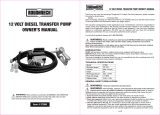
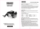
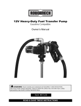
INTRODUCTION
The fuel box is made from high density polyethylene material. 1PC DC pump equipped with the
suction pipe, delivery hose and nozzle are fixed and installed internal of the box. For more
convenient operation, the pump and fittings are connected by rotating swivel connector.
PUMP: self-priming, volumetric, rotating vane pump, equipped with by-pass valve. With the
3/4in. rotating swivel connector.
The pump is designed to transfer diesel fuel only, for intermittent use with a working cycle of 30
minutes under maximum back pressure conditions.
MOTOR: Brush motor, DC, low tension with intermittent cycle, closed type in protection class
IP55, directly flanged to the pump body.
SUCTION TUBING:
- Minimum recommended nominal diameter: 3/4in.
- Nominal recommended pressure: 10bar/145PSI
- Use tubing suitable for functioning under suction pressure
DELIVERY TUBING:
- Minimum recommended nominal diameter: 3/4in.
- Nominal recommended pressure: 10bar/145PSI
Nozzle:
- Aluminum Manual nozzle
- Connection: 3/4in.
TECHNICAL SPECIFICATIONS
Portable Fuel Transfer Box Kit
OWNER’S MANUAL
Portable Fuel Transfer Box Kit OWNER’S MANUAL
Item#s 41874
1 of 9
WARNING: Read carefully and understand all INSTRUCTIONS before
operating. Failure to follow the safety rules and other basic safety
precautions may result in serious personal injury.
Model No.
Electrical power
Current
Fuses
Working pressure
Flow rate range
Delivery hose
41874
DC 12V
Max. 24 Amp
25
Max. 18 PSI
40 LPM/ 10GPM
3/4in. x 13ft.

Portable Fuel Transfer Box Kit OWNER’S MANUAL Portable Fuel Transfer Box Kit OWNER’S MANUAL
GENERAL SAFETY REGULATIONS
WARNING:
Read and understand all instructions.
WARNING: The warnings, cautions, and instructions discussed in this instruction
manual cannot cover all possible conditions or situations that could occur. It must be
understood by the operator that common sense and caution are factors that cannot be built
into this product, but must be supplied by the operator.
1. Keep the work area clean and dry. Damp or wet work areas can result in injury.
2. Keep children away from work area. Do not allow children to handle this product.
3. Store idle equipment. When not in use, tools and equipment should be stored in a dry
location to inhibit rust. Always lock up tools and equipment, and keep out of reach of
children.
4. Use the right tool for the job. Do not attempt to force small equipment to do the work of
larger industrial equipment. There are certain applications for which this equipment was
designed. It will do the job better and more safely at the capacity for which it was intended.
Do not modify this equipment, and do not use this equipment for a purpose for which it was
not intended.
5. Check for damaged parts. Before using this product, carefully check that it will operate
properly and perform its intended function. Check for damaged parts and any other conditions
that may affect the operation of this product. Replace damaged or worn parts immediately.
6. Do not overreach. Keep proper footing and balance at all times to prevent tripping, falling,
back injury, etc.
7. DO NOT use the equipment when tired or under the influence of drugs, alcohol, or
medication. A moment of inattention while operating this equipment may result in serious
personal injury.
8. Industrial applications must follow OSHA requirements.
SPECIFIC OPERATION WARNINGS
ELECTRICAL SAFETY
•
This pump
gets its electrical power from batteries. It demands the same respect that “corded”
tools demand. Remember, cordless tools are very capable of causing injury if all safety
precautions are not followed. Read and thoroughly understand the instruction manual that is
provided with the fuel pump.
WARNING:Always check to ensure the power supply corresponds to the voltage on
the rating plate.
•
Do not abuse the cables.
Never carry this pump by its cables, or yank pump or cable from the
battery. Keep cables away from heat, oil, sharp edges or moving parts. Replace damaged
cables immediately. Damaged cables may cause a fire and increase the risk of electric shock.
•
Avoid body contact
with grounded surfaces such as pipes, radiators, ranges, and refrigera-
tors. There is an increase risk of electric shock if your body is grounded.
•
Do not expose
your transfer pump to rain or wet conditions. Water entering a transfer pump
will increase the risk of electric shock.
•
Do not let your fingers
touch the terminals of plug when installing to or removing from the
battery.
PERSONAL SAFETY
•
Stay alert
, watch what you are doing and use common sense when operating a transfer pump.
Do not use a transfer pump while you are tired or under the influence of drugs, alcohol or
medication. A moment of inattention while operating transfer pumps may result in serious
personal injury.
•
Dress properly
. Do not wear loose clothing, dangling objects, or jewelry. Keep your hair,
clothing and
2 of 9
gloves away from moving parts. Loose clothes, jewelry or long hair can be caught in moving
parts. Air vents often cover moving parts and should be avoided.
•
Use safety apparel and equipment.
Use safety goggles or safety glasses with side shields which
comply with current national standards, or when needed, a face shield. Use as dust mask in dusty
work conditions. This applies to all persons in the work area. Also use non-skid safety shoes,
hardhat, gloves, dust collection systems, and hearing protection when appropriate.
•
Avoid accidental starting.
Do not carry the transfer pump with your finger on the switch.
Ensure the switch is in the off position before attaching to the battery.
•
Do not overreach.
Keep proper footing and balance at all times.
•
Remove adjusting keys or wrenches
before connecting to the power supply or turning on the
pump. A wrench or key that is left attached to a rotating part of the tool may result in personal
injury.
•
Prolonged contact with diesel fuel can damage the skin.
The use of glasses and gloves is
recommended.
PUMP USE AND CARE
•
Be aware that a cordless tool
can always be in an operating condition because it does not
have to be plugged into an electrical outlet. Unless the battery cables are disengaged, the
pump can function at any time the switch is turned on.
•
Do not force the tool.
Tools do a better and safer job when used in the manner for which they
are designed. Plan your work, and use the correct tool for the job.
•
Never use a transfer pump
with a malfunctioning switch. Any transfer pump that cannot be
controlled with the switch is dangerous and must be repaired by an authorized service
representative before using.
•
Disconnect battery
from the transfer pump and place the switch in the locked or off position
before making any adjustments, changing accessories, or storing transfer pumps. Such
preventive safety measures reduce the risk of starting the transfer pump accidentally.
•
When battery is not in use,
keep it away from other metal objects like: paper clips, coins,
keys, nails, screws, or other small metal objects that can make a connection from one terminal
to another. Shorting the battery terminals together may cause sparks, burns, or a fire.
•
Store idle tools.
When tools are not is use, store them in a dry, secure place out of the reach
of children. Inspect tools for good working condition prior to storage and before re-use.
•
Use only accessories that are recommended
by the manufacturer for your model. Accesso-
ries that may be suitable for one tool may create a risk of injury when used on another tool.
•
Do not expose battery
to moisture, frost or temperature extremes of over 110 degrees
Fahrenheit or under -20 degrees Fahrenheit.
•
Do not incinerate battery
or throw it into water even if it is damaged or is completely worn
out. Batteries can explode in a fire.
•
Keep guards in place
and in working order.
•
Never leave pump
running unattended.
•
Check that the quantity of diesel fuel in the suction tank
is greater than the amount you wish
to transfer.
•
Make sure that the residual capacity of the delivery tank
is greater than the quantity you
wish to transfer.
•
Do not run the pump dry
. This can cause serious damage to its components.
•
Never start or stop the pump by connecting or cutting out the power supply.
• Do not operate switches with wet hands.
• Diesel fuel leaks can damage objects and cause injuries.
• Make sure that the tubing and line accessories are in good condition.
OPERATING CONDITIONS
1. OPERATING ENVIRONMENTAL CONDITIONS
3 of 9

Portable Fuel Transfer Box Kit OWNER’S MANUAL Portable Fuel Transfer Box Kit OWNER’S MANUAL
Temperature
Min -4°F (-20°C) / Max +140°F (+60°C)
Relative Humidity:
Max 90%
2. ELECTRICAL POWER SUPPLY
The pump must be supplied by a single-phase alternating current line whose nominal values are
shown in the table
TECHNICAL SPECIFICATIONS
above. The maximum acceptable variation
from the electrical parameters is voltage ± 5% of the nominal value.
WARNING:Power supplied from lines with values outside the indicated limits can
damage the electrical components
3. WORKING CYCLE
ATTENTION
1. Extreme operating conditions with working cycles longer than 30 minutes can cause the motor
temperature to rise, thus damaging the motor itself.
2. Each 30-minute working cycle should always be followed by a 30-minute power-off cooling
phase.
3. MAXIMUM BY-PASSING TIME: 2 MINUTES.
4. DO NOT RUN DRY OVER 30 SECONDS.
WARNING:DO NOT KEEP THE PUMP WORKING IN BYPASS CONDITION MORE
THAN 2 MINUTES.
Whenever a particular installation carries the risk of functioning in bypass mode for longer
periods of time, it is necessary to return the bypassed flow to the suction tank; do not recirculate
inside the pump.
4. FLUID ALLOWED / FLUIDS NOT ALLOWED
ALLOWED:
DIESEL FUEL at a VISCOSITY from 2 to 5.35 cSt (at a temperature of 37.8)
Minimum Flash point (PM): 55
NOT ALLOWED:
WARNING:The gear pump is sensitive to polluted fluids; DO NOT deliver fluids with
impurities.
INSTALLATION OF PUMP
1. PRELIMINARY INSPECTION
• Check that the pump has not suffered any damage during transport.
• Clean the inlet and outlet openings with care, removing any dust or packing residue.
• Check that the electrical information corresponds with what is shown on the label.
2. CONNECTING THE TUBING
• Before connection, make sure that the tubing and the suction tank are free of dirt and thread
residue that could damage the pump and its accessories.
• Before connecting the delivery hose, partially fill the pump body with diesel fuel to avoid the
pump running dry during the priming phase.
4 of 9
• Do not use conical threaded joints that could damage the threaded pump openings if
excessively tightened.
• The pump is not provided with any filter. Always install suction filter.
Suction Tubing
• Minimum nominal recommended diameter: 3/4in.
• Use a hose suitable for functioning under suction pressure.
Delivery Tubing
• Minimum nominal recommended diameter: 3/4in.
WARNING:
1. Tubing and/or line components unsuitable for use with diesel fuel can cause damage to
objects or people, as well as pollution.
2. Use fuel-resistant pipe sealant or Teflon® Tape on all pipe threads.
3. Check all the connections before each use. Tighten them if necessary. Loosening of the
connections (threaded connections, flanging, gasket seals) can cause serious ecological and
safety problems.
3. SUCTION AND DELIVERY LINES
DELIVERY
The proper pump should be chosen considering the viscosity of the diesel fuel to be pumped
and the characteristics of the system attached to the delivery of the pump. The improper
application of the diesel fuel viscosity and the characteristics of the system could create
unexpected large back pressure, which may cause the (partial) opening of the pump bypass and
consequently reduce the flow rate.
It is recommended to use shorter tubing and/or tubing with larger diameter to reduce system
resistance, so that the pump would function equally to the viscosity of the diesel fuel being
pumped.
SUCTION
The model is equipped with a self-priming pump with a good suction capacity.
The pump will prime to a height of 6.5 feet (2 meters) when the suction hose is empty and the
pump is filled with the fluid during the start-up phase. Installing the pump at the same level with
the fluid level is perfect for the priming. Foot valve prevents the emptying of the suction tube and
keeps the pump wet. On tanks with a suction height over 6.5 feet, a foot valve may be required
on the bottom of the suction tube to hold the fluid in the tube. Do not install the pump with a
height higher than 9.8 feet (3 meters), or the pump will lose its prime.
WARNING:
(1) In the case that the suction tank is installed higher than the pump installation, it is recom-
mended to install an anti-siphon valve to prevent accidental diesel fuel leaks. Care should be
taken during the installation process in order to control back pressure.
(2) In applications where the pump is lower than the fuel nozzle, it is recommended that the
difference in height is not larger than 2m, in order to control the back pressure caused by
water hammer effect.
It is always advisable to prime the pump without an automatic delivery nozzle, verifying the
proper wetting of the pump.
The priming time can be as long as one minute and the pressure of
an automatic dispensing nozzle on the delivery line prevents the evacuation of air from the
installation, and, therefore, prevents proper priming.
When the system is functioning, the pump can work with pressure at the inlet as high as 0.5bar/7
PSI, beyond which cavitation phenomena can begin, with a consequent loss of flow rate and
increase of system noise.
It is important to guarantee low suction pressure by using short tubing
of a diameter equal to or larger than recommended, reducing curves to a minimum and using
suction filter of wide cross-section and foot valves with the lowest possible resistance.
5 of 9
NOT ALLOWED
Gasoline (Petrol)
Inflammable liquids with PM < 55
Water
Liquid food products
Corrosive Chemicals
Solvents
RELATED DANGER
Fire - explosion
Fire - explosion
Oxidation of the pump
Contamination
Corrosion of the pump
Injury to people
Fire – explosion
Damage to gasket seals

Portable Fuel Transfer Box Kit OWNER’S MANUAL
ATTENTION! Extreme operating conditions with working cycles longer than 30
minutes can cause the motor temperature to rise, thus damage the motor itself.
Each 30-minute working cycle should always be followed by a 30-minute power-off cooling
phase.
In the priming phase the pump must blow the air initially present in the entire installation out of
the delivery line. Therefore it is necessary to keep the outlet open to permit the evacuation of the
air.
ATTENTION! If an automatic type dispensing nozzle is installed at the end of the
delivery line, evacuation of the air will be difficult because of the automatic stopping
device that keeps the valve closed when the line pressure is too low. It is recommended that
the automatic dispensing nozzle be temporarily disconnected during the initial start-up
phase.
The priming phase may last from several seconds to a few minutes, depending on the character-
istics of the system.
If this phase is excessively prolonged, stop the pump and verify:
• That the pump is not running completely “dry”.
• That the suction hose is preventing air infiltration and is correctly immersed in the fluid to be
drawn.
• That any filters installed are not blocked.
• That the priming height is not greater than 6.5 feet (2 meters).
• That the delivery hose allows for the easy evacuation of air.
• When priming has occurred, after reattaching the delivery gun, verify that the pump is
functioning within the anticipated ranges, possibly checking:
1) That the suction pressure is not greater than 7psi.
2) That the back pressure in the delivery line does not exceed the values.
DAILY USE
1. The pump box includes 1pc DC pump, connecters, suction hose with filter, delivery hose and
manual nozzle. The completed pump kit is fixed in the box as a perfect portable fuel transfer
pump kit.
2. Before using, put the pump box on the fuel drum smoothly. Then take out the nozzle and
delivery hose, rotating the hose connectors to the best operation condition.
3. Take out the suction hose and rotating the hose connectors to best operation condition. Place
the suction hose with filter to the drum bottom.
4. Check all hoses and fittings. If they are working well, connect the power for dispensing.
5. After using, take out the suction hose and drain out the oil in the suction hose. After that, start
the pump and run dry for several seconds so as to drain out the remaining liquid in the pump
and hose.
NOTE: Keep the nozzle open during dry running.
6. After emptying the oil in the hose and pump, place the suction hose, delivery hose and nozzle
back to the box for better storing and moving.
ATTENTION! The pump can function with the delivery valve closed for brief periods
(2–3 minutes maximum). After use, make sure the pump is turned off.
MAINTENANCE
The pump is designed and constructed to require a minimum of maintenance. Following these
basic recommendations will improve pump performance and longevity.
• On a weekly basis, check that the tubing joints have not loosened, to avoid any leakage.
• On a monthly basis, check the pump body and keep it clean of any impurities.
• On a monthly basis, check and keep the pump filter clean and any other filters installed.
• On a monthly basis, check that the electric power supply cables are in good condition.
7 of 9
Portable Fuel Transfer Box Kit OWNER’S MANUAL
4. ELECTRICAL CONNECTIONS
The transfer pump features a terminal strip box with a safety fuse and pincers for connection to
a 12V battery. The terminal strip box features:
• ON/OFF switch;
• 25 Amp safety fuse against short circuits and overcurrent
• 6½-ft. power cable complete of pincers for connection to the battery
RED cable: positive pole (+)
BLACK cable: negative pole (-)
ATTENTION! IT IS THE INSTALLER’S RESPONSIBILITY TO PREFORM THE
ELECTRICAL CONNECTIONS WITH RESPECT FOR THE APPLICABLE REGULATIONS.
Respect the following (not exhaustive) instructions to ensure a proper electrical installation:
• During installation and maintenance, make sure that the electric supply lines are not live.
• Use cables characterized by the minimum cross-sections, nominal voltages and wiring-type
adequate to the electrical characteristics shown in the table
TECHNICAL SPECIFICATIONS
above and the installation environment.
• Always close the cover of the strip box before supplying electrical power.
• Check the correct rotation direction of the pump. If it is inverted, check the polarity of the
connection cable.
INITIAL STARTUP
• Check that the quantity of diesel fuel in the suction tank is greater than the amount you wish to
transfer.
• Make sure that the residual capacity of the delivery tank is greater than the quantity you wish
to transfer.
• Do not run the pump dry. This can cause serious damage to its components.
• Make sure that the tubing and line accessories and in good condition.
• Diesel fuel leak can damage objects and injure person.
• Never start or stop the pump by connecting or cutting out the power supply.
• Do not operate switches with wet hands.
• Prolonged contact with diesel fuel can damage the skin. The use of glasses and gloves is
recommended.
6 of 9

Portable Fuel Transfer Box Kit OWNER’S MANUAL
DIAGRAMS AND PARTS LIST
9 of 9
Portable Fuel Transfer Box Kit OWNER’S MANUAL
•
Under normal working conditions the noise emission from all models does not exceed the
value of 70 db at a distance of 1 meter from the electric pump.
TROUBLE SHOOTING
If the pump is not working properly, contact an authorized service representative. Do not
attempt to repair this pump yourself.
8 of 9
Part No.
1
2
3
4
5
6
Description
PLASTIC BOX
PUMP
SCREW
DELIVERY HOSES
SUCTION HOSES
NOZZLE
Q’ty
1
1
4
1
1
1
Part No.
7
8
9
10
11
12
Description
OUTLET TUBE
TUBE FITTING
SUCTION TUBE
FILTER
OIL CONTROL
LABEL
Q’ty
1
1
1
1
1
1
PROBLEM
Motor does not turn
Motor turns slowly when
starting
Little or no flow
Higher pump noise
Leakage from the pump
body
POSSIBLE CAUSE
Lack of power
Rotor jammed
Problems with the motor
Low voltage from the electrical power
supply
Low level in the suction tank
Foot valve blocked
Filter blocked
Excessive suction pressure
High load loss in the delivery circuit
(running with by-pass open)
By-pass valve blocked
Air in the pump or suction hose
Narrowing of the suction hose
Low rotation speed
The suction tubing is resting on the
bottom of the tank
Cavitation
Irregular by-pass functioning
Presence of the air in the diesel fuel
Damage to the mechanical seal
CORRECTIVE ACTION
Check electrical connections and
safety systems
Check for possible damage or
obstruction to rotating parts
Contact technical support
Adjust the voltage within anticipated
limits
Fill in the tank
Clean and/or replace valve
Clean the filter
Lower the pump with respect to the
level of the tank or increase the
cross-section of the hose
Use shorter hose or of wider diameter
Detach the valve, clean or replace it
Check the seal of the connection
Use a hose appropriate for working
under suction pressure
Check the voltage at the pump. Adjust
the voltage or use cables of greater
cross-section
Raise the tubing
Reduce the suction pressure
Deliver until the air in the by-pass
system is purged
Verify the suction connection
Check and replace the mechanical seal
1
23
4
5
6
7
11
9
10
8
12

Part No.
1
2
3
4
5
6
7
8
Description
SCREW M5×10
FRONT COVER
O-RING
VANES
ROTOR
MOTOR
O-RING
WASHER
Q’ty
16
1
1
5
1
1
2
4
Part No.
9
10
11
12
13
14
15
16
Description
PUMP BODY
MOTOR
O-RING
SCREW
JUNCTION BOX
FUSE
O-RING
BASE
Q’ty
1
1
2
2
1
1
1
1
Portable Fuel Transfer Box Kit OWNER’S MANUAL
17510413 PUMP
For replacement parts and technical questions, please call 1-800-222-5381.
WARRANTY
One-Year Limited Warranty
Distributed by
Northern Tool + Equipment Co., Inc.
Burnsville, MN 55306
NorthernTool.com
Made in Taiwan
1
2
3
4
5
6 8 9
10 11 12 13
14
7
15
16
Size:145x210mm 157G REV 04/30/20 2.09.05.30.473
/