Page is loading ...

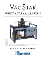
Installation & Maintenance
Instructions

Air Techniques, Inc.
Page
2
Model H-2 for VacStar 20
Congratulations! Your new HydroMiser, water recycling sys-
tem patented design incorporates many unique benefits:
• HydroMiser reduces VacStar’s water use by up to 75%.
• A built-in air/water separator keeps air and gases from
entering your sanitary waste lines.
• A built-in self-clearing drain device prevents solids
from accumulating within the liquid storage reservoir.
• A unique eductor fluid control system assures proper
water flow for optimum VacStar performance.
The HydroMiser, is available as Model H-2 for the VacStar 20
and Model H-4 used with VacStar 40.
Warning: The following steps must be performed
while wearing skin and eye protection
designed for handling typical Haz-Mat
material. Use care at all times to prevent
spillage.
Installation Specifications
1. Items A, D. & E are supplied.
2. Item B, 2" vent to outside is not
supplied.
3. Item C, 1-1/2" sanitary waste line is
not supplied.
4. If local codes prohibit a direct
waste connection as shown, use
hose supplied to route waste from
"E" to a floor sink or to an open
vertical 1-1/2" PVC waste line.
Important
• Install HydroMiser to the left, right,
or above of VacStar.
• Do not install HydroMiser below
VacStar.
• Maximum vertical distance between
the VacStar exhaust outlet and the
HydroMiser inlet is 3 feet. (36 in.)

Page
3Air Techniques, Inc.
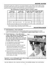
Installation Procedure
1. Preparing VacStar
A. Cut 3/8” Poly·Fio tubing (A), midway between
(B) and (C)
B. Install supplied union connectors on the cut
end of each tubing section.
• The 1/4” X 3/8” reducing union is
installed to the upper (B to A) tubing
section.
• The 3/8” X 3/8” union is installed to the
lower (C to A) tubing section.
NOTE:
Figure 1 shows VACSTAR 20.
VACSTAR 40 is similar except main power connection is
made via provided hospital grade NEMA 6-15P line cord.
Figure 1. VacStar 20 and 40 Preparation
V
A C
S
TAR
®
B
A
C
Push To Connect
Water Inlet
Connector
As shown by Figure 2, install the sup-
plied pressure regulator on the water
supply line.
3. Connections between the VacStar and HydroMiser
Connect the 1/4” tubing, the 3/8” tubing and the 3/4” hose between HydroMiser and the VacStar as
shown by Figure 3.
Figure 2. Pressure Regulator Installation
Pressure
Gauge
¼ inch tube
to Water Inlet
Connector
Pressure
Regulator
Water Inlet
Strainer
½ inch FNPT
Shut-Off
Valve
2. Water Pressure Regulator Installation
Figure 3. HydroMiser Installation
VA C STAR
®
3/8” tubing with 3/8” X 1/4”
reducing union that accepts
1/4” Hydromiser connection.
A
B
3/4” drain hose connection to
top of Hydromiser.
See Figure 4 for Hydromiser
drain connection options.
C
B
A1/4”
3/8”
3/8” tubing with 3/8” X 3/8”
union connector that accepts
3/8” Hydromiser connection.
C3/4”

© Air Techniques, Inc. • P/N 55266, Rev. G • June 2018
www.airtechniques.com
Warning: The following steps must be performed while wearing skin and eye protection designed for
handling typical Haz-Mat material. Use care at all times to prevent spillage.
Caution: Use only CleanStream Cleaner to maintain the system vacuum lines. Do not use chlorine bleach
or solutions of sodium hypochlorite to disinfect the MOJAVE system. These materials may result
in damage or destruction of equipment or loss of system performance.
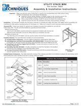
Daily Maintenance - Clean Vacuum Lines
Follow directions provide with product instructions and clean all vacuum lines in the vacuum system
with CleanStream Cleaner daily as part of the overall preventive maintenance program. This helps to
maintain the cleanliness of the tank as well as the vacuum lines and tubing throughout the system.
Using the 2.5 liter bottle of CleanStream Cleaner, PN 57850 and the CleanStream dispenser system,
PN 57665.
CleanStream Dispenser System,
Part No. 57665
Part No. 57850
Part No. Description
57850 2.5 Liter Bottle CleanStream Cleaner (125 applications)
57665 CleanStream Dispenser System
1 Bottle with o-rings and caps
1 Saliver Ejector Adapter
1 High-Volume Actuator Adapter
1 Small Suction Hose Adapter
1 Large Suction Hose Adapter
Required - Not Supplied
IMPORTANT NOTE:
ALL INSTALLATIONS
Ambient temperature for all VacStar installations should
be 40°- 104°F (5°- 40°C).
The liquid drain from the HydroMiser must slope down-
ward at least 1/4" for every 10 feet of run toward the
drain.
(Avoid local low sections, avoid creating traps in the line.)
Figure 4. Drain Connection Options
1” hose 1” hose
Maintenance
Air Techniques
1295 Walt Whitman Road
Melville, New York 11747
1” hose for Hydromiser
either drain connection
option shown below.
/