Page is loading ...

This kit includes:
PART NUMBER DESCRIPTION Quantity
30920 Lock Washer, 1/4” 3
55142 Separator Drain Hose Assembly w/ Elbow 1
55981 Exhaust Hose Assembly w/Teflon 1
55499 Eductor Assembly for VS80 w/Bracket 80H 1
55498 Eductor Assembly for VS50 w/Bracket 50H 1
55147 1/2” Poly flow tubing, 14” 1
55231 1/4” Poly flow tubing, 17-1/4” 1
30822 Bolt 1/4-20 x 1/2” Hex Head 3
30711 Screw; 10-24 x 1/2” Hex Head Washer 2
55264 Hose and Cuff Assembly 1
49833 Hose Clamp 2
56006 HydroMiser Assembly w/ Bracket & Water System VS80 1
57278 1” Rubber Coupling (incl. with HydroMiser Assy) 1
56005 HydroMiser Assembly w/Bracket & Water System VS50H 1
55927 Adapter Fitting, 1” MNPT x 1” Barb 1
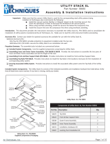
HYDROMISER INSTALLATION KIT
INSTRUCTIONS
PN 56041 for VacStar 50 (VS50)
PN 56042 for VacStar 80 (VS80)
Tools needed for this installation:
7/16” Wrench 5/16” nut driver Philips screw driver Cutter Tape Measure
Adjustable Pliers
Review the FLOW DIAGRAM, below, before beginning installation.

PREPARE THE VACSTAR TO RECEIVE THE HYDROMISER ASSEMBLY
Note: 36” height clearance required for proper vent installation
A. Disconnect the power and shut off the water supply.
B. Disconnect the water distribution system (See Fig 1).
1. Disconnect both 3/8” poly flow tubes at the water distribution system.
2. The other end of the 3/8” poly flow tubes are connected to the pump housing. Measure 13-1/2”
from the tube fittings on the pump housing. Cut off the excess tubing.
3. Disconnect both 1/4” poly flow tubes at the bottom of the water distribution system.
Note: When reconnecting these tubes, they must be reconnected in the same way they were
disconnected as one tube is longer than the other.
4. Remove and discard both water distribution systems from the back rail using a Phillips screw driver
to disengage the clamp.
C. Remove and discard the existing exhaust hose and fitting between the exhaust
manifold and the drain.
Cut off the exhaust hose. Use adjustable pliers to unscrew the rest of the fitting (See Figs. 1 & 6).
2

INSTALL HYDROMISER ASSEMBLY, EDUCTOR, REATTACH TUBING
A. Install the eductor; connect poly flow tubing
1. Using a 5/16” nut driver and 2 hex head screws provided,
attach the eductor block’s bracket to the base plate of the
VacStar chassis. Set the eductor on recycle mode (See Fig. 3).
2. Route the 3/8” poly flow tube from the left pump assembly
over the intake manifold to the left port of the”Y” connector
on the eductor block. Insert until the tube stops.
3. Route the 3/8” poly flow tube
from the right pump assembly
to the right port of the “Y”
connector on the eductor block.
Loop tubes; avoid kinks.
Insert until the tube stops.
4. Insert the 1/2” poly flow tube
(incl. w/kit) into the side port of
the eductor block until the tube
stops.
5. Attach 1/4” poly flow tube
(incl.w/kit) to fitting on back
of block (See Fig. 3).
C. Connect the poly flow tubing to HydroMiser Assembly (See Fig. 5).
1. Reconnect the 1/4” poly flow tubes between the bottom of the water distribution system and the sole-
noids.
Note: When reconnecting these tubes, they must be reconnected in the same way they were disconnected
as one tube is longer than the other.
2. Insert the free end of the 1/2” poly flow tube into the swivel fitting of the HydroMiser assembly until the
tube stops. (See Fig. 2).
3. Connect the 1/4” poly flow tube from the back of the eductor block, (See Fig. 3), to the elbow found
at the top of the water distribution system (See Fig. 5).
NOTE: If, for any reason, it becomes necessary to remove a poly flow
tube held in place with a push to connect fitting, simply
push the outer ring in and pull on the tube.
B. Attach the HydroMiser assembly to the back rail of
the VacStar.
Use 3 bolts and 3 lock washers (incl. w/kit). Use a 7/16” wrench
(See Fig. 4).
3

D. Attach the Exhaust hose (See Fig.6).
1. Screw the 1” mnpt end of the exhaust hose assembly
(incl. w/kit) into the exhaust manifold and tighten.
This fitting is pre-taped with Teflon tape.
2. Attach the other 3/4” FGHT end of the hose to the
Hydro Miser Assembly inlet and tighten.
3. If the exhaust hose is too long, cut it to the correct
length & attach supplied adapter fitting, reuse clamp.
E. Connect the drain hose
1. Connect the drain hose assembly to the drain outlet with
the 1” black rubber coupling. Use a 5/16” nut driver (See Fig. 2).
2. Connect the other end of the drain hose to the building drain. (See Fig. 5)
for proper drain connections. The drain installation must conform to local codes.
F. Connect the Hose and Cuff assembly
1. Connect the Hose and Cuff assembly to the HydroMiser assembly using the hose clamp,
(incl. w/kit). Use a 5/16” nut driver (See Fig. 4).
2. Connect the other end of the Hose and Cuff assembly to the building vent using a hose
clamp (incl. w/kit). Use a 5/16” nut driver.
CHECK OUT PROCEDURE
1. Reconnect the power and turn on the water supply.
2. Close all HVE’s and SE’s and turn on the VacStar.
3. If leaks are present, turn off the unit and repair accordingly.
4. If no leaks are present, turn on the VacStar and set the eductor to recycle mode (See Fig. 4).
Note the reading on the vacuum gauge. Then, set the eductor to bypass mode. Note the reading
again on the vacuum gauge. If there is no more than 1 In Hg. difference between readings, the
HydroMiser has been installed successfully.
5. If the readings are not the same or widely different, review the installation. If the HydroMiser was
installed correctly, see the VacStar Service Technicians Manual, Trouble Shooting Guide, Low or No
Suction.
VacStar is a trademark of Air Techniques, Inc.
© Copyright 2004 Air Techniques, inc.
PN 55377, Rev. C 11/2016
Air Techniques, Inc.
1295 Walt Whitman Road
Melville, New York, USA 11747- 3062
/