Page is loading ...

RFID System
Man. No.: Z271-E1-07
ID Sensor Units
CS1W-V680C11
CS1W-V680C12
CJ1W-V680C11
CJ1W-V680C12
V680 Series
User’s Manual
V680C12
RUN
ERC
HEAD1
T/R
NORM/ERR
ERP
ERH
HEAD2
T/R
NORM/ERR
TEST
ON
HEAD1
HEAD2
DC24V
INPUT
+
-
V680C11
RUN
ERC
HEAD1
T/R
NORM/ERR
ERP
ERH
HEAD2
T/R
NORM/ERR
TEST
ON
HEAD

Introduction
Thank you for purchasing an ID Sensor Unit for a V680/V680S-series RFID System. This manual describes
the functions, performance, and application methods needed for optimum use of your V680/V680S-series
RFID System.
Please observe the following items when using the V680/V680S-series RFID System.
• Allow the V680/V680S-series RFID System to be installed and operated only by qualified specialist with a
sufficient knowledge of electrical systems.
• Read and understand this manual before attempting to use the V680/V680S-series RFID System and use
the V680/V680S-series RFID System correctly.
• Keep this manual in a safe and accessible location so that it is available for reference when required.

Introduction SECTION 1 SECTION 2 SECTION 3 SECTION 4 SECTION 5 SECTION 6 SECTION 7 SECTION 8
Introduction
Section 1
Section 2
Section 3
Section 4
Section 5
Section 6
Section 7
Section 8
READ AND UNDERSTAND THIS DOCUMENT
Features and System Configuration
CS-series ID Sensor Units
CJ-series ID Sensor Units
Data Exchange with the CPU Unit
ID Sensor Unit Functions
Controlling the ID Sensor Unit
Troubleshooting Alarms and Errors
Appendices
RFID System
CS1W-V680C11 ID Sensor Unit
CS1W-V680C12 ID Sensor Unit
CJ1W-V680C11 ID Sensor Unit
CJ1W-V680C12 ID Sensor Unit
User's Manual

2
Introduction
RFID System
User's Manual
Introduction
READ AND UNDERSTAND THIS DOCUMENT
Please read and understand this document before using the products. Please consult your OMRON representative if you have any questions or comments.
WARRANTY
OMRON’s exclusive warranty is that the products are free from defects in materials and workmanship for a period of one year (or other period if specified)
from date of sale by OMRON.
OMRON MAKES NO WARRANTY OR REPRESENTATION, EXPRESS OR IMPLIED, REGARDING NON-INFRINGEMENT, MERCHANTABILITY, OR FIT-
NESS FOR PARTICULAR PURPOSE OF THE PRODUCTS. ANY BUYER OR USER ACKNOWLEDGES THAT THE BUYER OR USER ALONE HAS
DETERMINED THAT THE PRODUCTS WILL SUITABLY MEET THE REQUIREMENTS OF THEIR INTENDED USE. OMRON DISCLAIMS ALL OTHER
WARRANTIES, EXPRESS OR IMPLIED.
LIMITATIONS OF LIABILITY
OMRON SHALL NOT BE RESPONSIBLE FOR SPECIAL, INDIRECT, OR CONSEQUENTIAL DAMAGES, LOSS OF PROFITS OR COMMERCIAL LOSS IN
ANY WAY CONNECTED WITH THE PRODUCTS, WHETHER SUCH CLAIM IS BASED ON CONTRACT, WARRANTY, NEGLIGENCE, OR STRICT LIABIL-
ITY.
In no event shall responsibility of OMRON for any act exceed the individual price of the product on which liability is asserted.
IN NO EVENT SHALL OMRON BE RESPONSIBLE FOR WARRANTY, REPAIR, OR OTHER CLAIMS REGARDING THE PRODUCTS UNLESS OMRON’S
ANALYSIS CONFIRMS THAT THE PRODUCTS WERE PROPERLY HANDLED, STORED, INSTALLED, AND MAINTAINED AND NOT SUBJECT TO CON-
TAMINATION, ABUSE, MISUSE, OR INAPPROPRIATE MODIFICATION OR REPAIR.
SUITABILITY FOR USE
THE PRODUCTS CONTAINED IN THIS DOCUMENT ARE NOT SAFETY RATED. THEY ARE NOT DESIGNED OR RATED FOR ENSURING SAFETY OF
PERSONS, AND SHOULD NOT BE RELIED UPON AS A SAFETY COMPONENT OR PROTECTIVE DEVICE FOR SUCH PURPOSES. Please refer to sep-
arate catalogs for OMRON's safety rated products.
OMRON shall not be responsible for conformity with any standards, codes, or regulations that apply to the combination of products in the customer’s applica-
tion or use of the product.
At the customer’s request, OMRON will provide applicable third party certification documents identifying ratings and limitations of use that apply to the prod-
ucts. This information by itself is not sufficient for a complete determination of the suitability of the products in combination with the end product, machine,
system, or other application or use.
The following are some examples of applications for which particular attention must be given. This is not intended to be an exhaustive list of all possible uses
of the products, nor is it intended to imply that the uses listed may be suitable for the products:
• Outdoor use, uses involving potential chemical contamination or electrical interference, or conditions or uses not described in this document.
• Nuclear energy control systems, combustion systems, railroad systems, aviation systems, medical equipment, amusement machines, vehicles, safety
equipment, and installations subject to separate industry or government regulations.
• Systems, machines, and equipment that could present a risk to life or property.
Please know and observe all prohibitions of use applicable to the products.
NEVER USE THE PRODUCTS FOR AN APPLICATION INVOLVING SERIOUS RISK TO LIFE OR PROPERTY WITHOUT ENSURING THAT THE SYSTEM
AS A WHOLE HAS BEEN DESIGNED TO ADDRESS THE RISKS, AND THAT THE OMRON PRODUCT IS PROPERLY RATED AND INSTALLED FOR THE
INTENDED USE WITHIN THE OVERALL EQUIPMENT OR SYSTEM.
PERFORMANCE DATA
Performance data given in this document is provided as a guide for the user in determining suitability and does not constitute a warranty. It may represent the
result of OMRON’s test conditions, and the users must correlate it to actual application requirements. Actual performance is subject to the OMRON Warranty
and Limitations of Liability.
CHANGE IN SPECIFICATIONS
Product specifications and accessories may be changed at any time based on improvements and other reasons.
It is our practice to change model numbers when published ratings or features are changed, or when significant construction changes are made. However,
some specifications of the product may be changed without any notice. When in doubt, special model numbers may be assigned to fix or establish key spec-
ifications for your application on your request. Please consult with your OMRON representative at any time to confirm actual specifications of purchased prod-
ucts.
DIMENSIONS AND WEIGHTS
Dimensions and weights are nominal and are not to be used for manufacturing purposes, even when tolerances are shown.
ERRORS AND OMISSIONS
The information in this document has been carefully checked and is believed to be accurate; however, no responsibility is assumed for clerical, typographical,
or proofreading errors, or omissions.
PROGRAMMABLE PRODUCTS
OMRON shall not be responsible for the user’s programming of a programmable product, or any consequence thereof.
COPYRIGHT AND COPY PERMISSION
This document shall not be copied for sales or promotions without permission. This document is protected by copyright and is intended solely for use in con-
junction with the product. Please notify us before copying or reproducing this document in any manner, for any other purpose. If copying or transmitting this
document to another, please copy or transmit it in its entirety.

3
RFID System
User's Manual
Introduction
Introduction
Signal Words Used in This Manual
The following signal words and symbols are used in this manual to indicate precautions that must be observed
to ensure safe use of the V680-series ID Sensor Unit. The precautions provided here contain important safety
information. You must observe these precautions.
The following signal words and symbols are used in this manual.
Meanings of Alert Symbols
Safety Precautions
Indicates a potentially hazardous situation which, if not avoided, will result in minor or
moderate injury, or may result in serious injury or death. Additionally there may be
significant property damage.
Indicates a potentially hazardous situation which, if not avoided, may result in minor
or moderate injury or in property damage.
General Caution
Indicates general cautionary, warning, or danger level information.
Electrical Shock Caution
Indicates possibility of electric shock under specific conditions.
General Prohibition
Indicates a general prohibition.
Disassembly Prohibition
Indicates that disassembly is prohibited to prevent electric shock.
General Mandatory Action
Indicates a general action that must be performed by the user.
WARNING
CAUTION

4
Introduction
RFID System
User's Manual
Introduction
Warnings
Never attempt to disassemble any Units while power is being supplied. Doing so may result in
serious electrical shock or electrocution.
Never touch any of the terminals while power is being supplied. Doing so may result in
serious electrical shock or electrocution.
Provide safety measures in external circuits, l.e., not in the PLC (CPU Unit including associated Units), in
order to ensure safety in the system if an abnormality occurs due to malfunction of the PLC or another
external factor affecting the PLC operation. Not doing so may result in serious accidents.
•Emergency stop circuits, interlock circuits, limit cuicuits, and similar safety measures must be provided in
external control circuits.
•The PLC will turn OFF all outputs when its self-diagnosis function detects any error or when a severe failure
alarm (FALS) instruction is executed. As a countermeasure for such errors, external safety measures must
be provided to ensure safety in the system.
•The PLC outputs may remain ON or OFF due to deposition or burning of the output relays or
destruction of the output transistors, As a countermeasure for such problems, external
safety measures must be provided to ensure safety in the system.
This Product is not designed or rated for ensuring safety of persons. Do not use it for such
purposes.
Execute online edit only after confirming that no adverse effects will be caused by extending
the cycle time. Otherwise, the input signals may not be readable.
WARNING
CAUTION

5
RFID System
User's Manual
Introduction
Introduction
Be sure to observe the following precautions to ensure safe use of the Product.
1. Do not attempt to disassemble, repair, or modify the Product.
2. Tighten the Backplane mounting screws and terminal block screws securely.
3. Be sure to use crimp terminals of the specified size for wiring.
4. If any cable has a locking mechanism, make sure that it has been locked before using the cable.
5. Make sure the power supplied by the DC Power Supply Unit is within the rated power supply voltage
(24 VDC +10%/−15%) before using the Product.
6. When using the CS1W-V680C12, make sure the power supplied by the DC power supply for external
inputs is within the rated power supply voltage (24 VDC +10%/−15%) before using the Product.
7. Do not connect the power supply in reverse.
8. Use crimp terminals for wiring. Do not connect bare stranded wires directly to terminals.
9. Do not allow water or wires to enter the Product through gaps in the case. Otherwise, fire or electric shock
may occur.
10. Turn OFF the power to the Product before attaching or removing an Amplifier or Antenna.
11. If multiple Antennas are mounted near each other, communications performance may decrease due to
mutual interference. Refer to information on installing Antenna in the RFID System V680 Series User's
Manual for Amplifiers, Antennas, and RF Tags (FRAM) (Cat. No. Z248), V680 Series RFID System
Amplifier/RF Tags (EEPROM) User's Manual (Cat. No. Z262), and Heat-resistive RFID System V680
Series User's Manual (Cat. No. Z221) and check to make sure there is no mutual interference.
12. If an error is detected in the Product, immediately stop operation and turn OFF the power supply. Consult
with an OMRON representative.
13. Dispose of the Product as industrial waste.
14. Observe all warnings and precautions given in the body of this manual.
15. Do not use thinners, benzenes, acetones, and kerosenes for cleaning.
Precautions for Safe Use

6
Introduction
RFID System
User's Manual
Introduction
Always observe the following precautions to prevent operation failure, malfunctions, and adverse effects on
performance and equipment.
1. Installation Environment
Do not use the Product in the following locations.
• Locations exposed to any flammable, explosive, or corrosive gasses
• Locations exposed to dust, metallic powder, or salts
• Locations not within the specified operating temperature range
• Locations subject to rapid changes in temperature or condensation
• Locations not within the specified operating humidity range
• Locations subject to direct vibration or shock outside the specified ranges
• Locations subject to spray of water, oil, or chemicals
2. Installation
• This Product uses a frequency band of 13.56 MHz to communicate with RF Tags. Some transceivers,
motors, inverters, switching power supplies, etc., generate electrical noise that will affect these com-
munications. If any of these devices are located in the vicinity of the Product, they may affect
communications with RF Tags, and may possibly damage the RF Tags. Prior to using the Product in
the vicinity of any of these devices, perform a test to determine whether the Product can be used
under the resulting influence.
• Observe the following precautions to minimize the effects of normal noise.
(1) Ground the ground terminal on the Product and all metal objects in the vicinity of the Product to
100 Ω or less.
(2) Do not use the Product near high-voltage or high-current lines.
• The Product is not waterproof. Do not use it in an environment where mist is present.
• Do not expose the Product to chemicals that adversely affect the Product materials.
• Use a tightening torque of 0.4 N⋅m hen mounting the Product.
3. Storage
• Locations exposed to any flammable, explosive, or corrosive gasses
• Locations exposed to dust, metallic powder, or salts
• Locations not within the specified operating temperature range
• Locations subject to rapid changes in temperature or condensation
• Locations not within the specified operating humidity range
• Locations subject to direct vibration or shock outside the specified ranges
• Locations subject to spray of water, oil, or chemicals
Precautions for Correct Use

7
RFID System
User's Manual
Introduction Precautions for Users of V600-series ID Sensor Units
Introduction
Precautions for Users of V600-series ID Sensor Units
Differences between the V600-series and V680-series ID Sensor Units
The following features were added to the V680-series ID Sensor Units in comparison to the V600-
series Units. Functions are upwardly compatible, so V600-series Units can be easily replaced with
V680-series Units.
Commands • Read with Error Correction
• Write with Error Correction
• UID Read
• Noise Measurement
Communications specifica-
tions
• FIFO trigger
• FIFO repeat
• Multi-access trigger
• Multi-access repeat
DM Area settings • UID Addition Setting
• Write Protection Disable Setting
• Antenna Connection Setting (V680-H01)
• Results Monitor Output Setting
• Test Operation Setting
• Run/Test Switching Method Setting
Test Operations
(Set in the DM Area)
• Range level measurement
• Read/Write speed level measurement
• Noise level measurement
• Communications success rate measurement
CIO Area outputs Run/Test Bit
(Only when using the Run/Test Switching Method Setting is enabled in the DM Area.)
CIO Area inputs • Antenna Error Flag (9C)
• ID System Error 1 (79)
• ID System Error 2 (7E)
• ID System Error 3 (7F)
• Error Correction Flag (77)
• Results Output Monitor
Run Mode: Communications time or noise level
Test Mode: Result contents of tests
Others If a command error or data storage area error occurs in a V600-series ID Sensor Unit, the
Error End Flag will not be turned ON. With a V680-series ID Sensor Unit, the Error End Flag
will be turned ON for these errors.
With a V600-series ID Sensor Unit, command errors and data storage errors are not moni-
tored in the Processing Results Monitor, but a V680-series ID Sensor Unit will monitor them
and use an error code of E014.
∗ FIFO trigger, FIFO repeat, Multi-access trigger, and
Multi-access repeat specification cannot be used for
communicating with V680-D1KP@@ RF Tags.

8
Introduction Meanings of Symbols
RFID System
User's Manual
Introduction
Meanings of Symbols
Indicates particularly important points related to a function, including precautions and application advice.
Indicates page numbers containing relevant information.
Indicates reference to helpful information and explanations for difficult terminology.

9
RFID System
User's Manual
Introduction
Introduction
Table of Contents
Introduction 1
Safety Precautions 3
Precautions for Safe Use 5
Precautions for Correct Use 6
Precautions for Users of V600-series ID Sensor Units 7
Meanings of Symbols 8
Table of Contents 9
Features and System Configuration 11
Outline of Features and Functions 12
Using Heat-resistive RF Tags (V680-D1KP58HTN and V680-D1KP58HT) 15
Using V680S-D8KF 20
System Configuration 21
Functions by Application 27
CS-series ID Sensor Units 29
Specifications 30
Operating Procedure 32
Part Names and Functions 38
Connections and Wiring 41
CJ-series ID Sensor Units 45
Specifications 46
Operating Procedure 48
Part Names and Functions 54
Connections and Wiring 57
Data Exchange with the CPU Unit 61
Outline of Data Exchange 62
Initial Settings Data 65
I/O Data Allocations 67
@@ RF Tags

10 RFID System
User's Manual
Introduction
Introduction
ID Sensor Unit Functions 77
Operating Modes 78
Communications Specifications 85
Parameter Settings in DM Area 93
RF Tag Memory 99
Write Protection 101
RF Tag Service Life Check 108
RF Tag Memory Check 112
RF Tag Memory Error Correction 114
Controlling the ID Sensor Unit 117
ID Sensor Unit Operation 118
Communications Commands 125
Communications Time 141
Troubleshooting Alarms and Errors 145
Indicators and Error Check Flowcharts 146
ID Sensor Unit Alarms 148
CPU Unit Errors 151
Restarting Special I/O Units 152
Troubleshooting 153
Appendices 157
Dimensions 158
Sample Programming 160
Data Coding Tables 204
Degree of Protection 208
Revision History 210


12
SECTION 1 Outline of Features and Functions
RFID System
User's Manual
SECTION 1
Features and System Configuration
Outline of Features and Functions
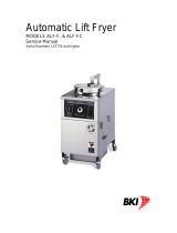
• SYSMAC CS-series ID Sensor Units
These ID Sensor Units are used in SYSMAC CS-series PLCs to read and write data for V680-series RF Tags.
There are two models: a One-channel ID Sensor Unit (CS1W-V680C11) and a Two-channels ID Sensor Unit
(CS1W-V680C12).
V680C11
RUN
ERC
T/R
NORM/ERR
ERP
ERH
TEST
ON
HEAD
V680C12
RUN
ERC
HEAD1
T/R
NORM/ERR
ERP
ERH
HEAD2
T/R
NORM/ERR
TEST
ON
HEAD1
HEAD2
DC24V
INPUT
Two-channels ID Sensor Unit
(CS1W-V680C12)
One-channel ID Sensor Unit
(CS1W-V680C11)

SECTION 1 Outline of Features and Functions
SECTION 1
Features and System Configuration
13
RFID System
User's Manual
• SYSMAC CJ-series ID Sensor Units
These ID Sensor Units are used in SYSMAC CJ-series PLCs to read and write data for V680-series RF Tags.
There are two models: a One-channel ID Sensor Unit (CJ1W-V680C11) and a Two-channels ID Sensor Unit
(CJ1W-V680C12).
• An RFID system consists of an ID Sensor Unit in a CS-series/CJ-series CPU Rack or CS-series/CJ-series
Expansion Rack, one or two Antennas connected to the ID Sensor Unit, and RF Tags connected to moving
bodies.
• The ID Sensor Unit operates through the Antennas to write data from the CS/CJ-series CPU Unit to the RF
Tags and read data from the RF Tags to the CS/CJ-series CPU Unit.
CS1W-V680C11 CS1W-V680C12 CJ1W-V680C11 CJ1W-V680C12
Amplifier/
Antennas
V680 Series (V680-HA63@/V680-H@@)
Maximum
number of
connected
Antennas
1212
RF Tags V680 Series (V680-D@@F@@ or V680-D@@P@@)
Commands Read
Write
Bit Set
Bit Clear
Mask Bit Write
Calculation Write
Data Fill
Data Check
Number of Writes Control
Read with Error Correction
Write with Error Correction
UID Read
Noise Measurement
Read
Write
Bit Set
Bit Clear
Mask Bit Write
Calculation Write
Data Fill
Data Check
Number of Writes Control
Copy
Read with Error Correction
Write with Error Correction
UID Read
Noise Measurement
Read
Write
Bit Set
Bit Clear
Mask Bit Write
Calculation Write
Data Fill
Data Check
Number of Writes Control
Read with Error Correction
Write with Error Correction
UID Read
Noise Measurement
Read
Write
Bit Set
Bit Clear
Mask Bit Write
Calculation Write
Data Fill
Data Check
Number of Writes Control
Copy
Read with Error Correction
Write with Error Correction
UID Read
Noise Measurement
One-channel ID Sensor Unit
(CJ1W-V680C11)
Two-channels ID Sensor Unit
(CJ1W-V680C12)

14
SECTION 1 Outline of Features and Functions
RFID System
User's Manual
SECTION 1
Features and System Configuration
Differences between Version 1.2 and Pre-Version 1.2
The following functions have been added to version 1.2 in comparison to pre-version 1.2. Functions are
upwardly compatible, so pre-version 1.2 can be replaced with version 1.2.
CA1D Mode Setting Added for RF Tag Memory
If you are using a V680-CA1D/-CA2D ID Controller, always set the RF Tag memory setting to CA1D
Mode. Setting the RF Tag memory setting to CA1D Mode enables reading and writing Heat-resistant
RF Tags (V680-D1KP58HTN and V680-D1KP58HT) that were written by the V680-CA1D/-CA2D.
New Data Transfer Setting
In addition to cyclically transferring 160 bytes/scan, Intelligent I/O Instructions can now be used to
transfer up to 2,048 bytes in one scan.
Parameters Added to Data Memory Allocation
DM Area allocations now include a RF Tag memory setting and data transfer setting.
Refer to DM Area Allocations and Contents on page 65 for details on the DM Area.
p. 65
A label on the side of the ID Sensor Unit shows the version for Units with version 1.2 or newer.
A different memory map may be used when reading or writing Heat-resistant RF Tags that were written by the V680-
CA1D/-CA2D from a Reader/Writer that is manufactured by a company other than OMRON. Refer to Operation When
RF Tag Memory Setting Is Set to Standard Mode in this section.
p. 18
Version
Version
• CS1W-V680C1@• CJ1W-V680C1@

SECTION 1 Using Heat-resistive RF Tags (V680-D1KP58HTN and V680-D1KP58HT)
SECTION 1
Features and System Configuration
15
RFID System
User's Manual
Using Heat-resistive RF Tags (V680-D1KP58HTN
and V680-D1KP58HT)
This section provides information for using Heat-resistive RF Tags (V680-D1KP58HTN or V680-D1KP58HT).
If you are not using a Heat-resistive RF Tag, set the RF Tag memory setting to Standard Mode.
Precautions for Saving Data at High Temperatures
If you are using Heat-resistive RF Tags (V680-D1KP58HTN or V680-D1KP58HT), write the data again
after saving data at a high temperature even if it is not necessary to change the data. A " high tempera-
ture" is one between 110°C and 200°C.
Using a Controller for a Heat-resistant RFID System (V680-
CA1D/-CA2D)
If you are using Heat-resistive RF Tags (V680-D1KP58HTN or V680-D1KP58HT) and also using a
V680-CA1D/-CA2D ID Controller, set the RF Tag memory setting of the ID Sensor Unit (version 1.2 or
newer) to CA1D Mode.
A label on the side of the ID Sensor Unit shows the version for Units with version 1.2 or newer.
If you are not using the V680-CA1D/-CA2D, the RF Tag memory setting does not need to be changed.
Refer to information in System Configuration.
Combining the V680-CA1D/-CA2D with Other V680-series Models
When using other models of Controller with the V680-CA1D/-CA2D, make sure that the version allows
setting the RF Tag memory setting to CA1D Mode.
To use the CS/CJ1W-V680C1@, it must be version 1.2 or newer.
To use the V680-CD5D01-V2, it must be version 2.3 or newer.
To use the V680-CH@D, it must be version 1.1 or newer.
A label on the side of the ID Sensor Unit shows the version for Units with version 1.2 or newer.
Version
Version
• CS1W-V680C1@• CJ1W-V680C1@
Version
Version
• CS1W-V680C1@• CJ1W-V680C1@

16
SECTION 1 Using Heat-resistive RF Tags (V680-D1KP58HTN and V680-D1KP58HT)
RFID System
User's Manual
SECTION 1
Features and System Configuration
Precautions when Setting the RF Tag Memory Setting to CA1D
Mode
Applicable RF Tags
Only the V680-D1KP
@@
RF Tags can be used when the RF Tag memory setting is set to CA1D Mode.
V680-D
@
KF
@@
RF Tags cannot be used.
CA1D Mode Setting for RF Tag Memory and Write Protection
When setting the RF Tag memory setting to CA1D Mode, always disable write protection.
Set word m+2 (Write Protection Setting) in the DM Area to 01 to disable write protection.
Refer to DM Area Allocations and Contents on page 65 for details on the DM Area.
p. 65
RF Tags That Can Be Used RF Tags That Cannot Be Used
Model Model
V680-D1KP58HT V680-D2KF52M
V680-D1KP58HTN V680-D2KF52M-BT01
V680-D1KP52MT V680-D2KF52M-BT11
V680-D1KP52M-BT01 V680-D8KF67
V680-D1KP52M-BT11 V680-D8KF67M
V680-D1KP53M V680-D8KF68
V680-D1KP66T V680-D32KF68
V680-D1KP66MT V680S-D2KF67
V680S-D2KF67M
V680S-D2KF68
V680S-D2KF68M
V680S-D8KF67
V680S-D8KF67M
V680S-D8KF68
V680S-D8KF68M

SECTION 1 Using Heat-resistive RF Tags (V680-D1KP58HTN and V680-D1KP58HT)
SECTION 1
Features and System Configuration
17
RFID System
User's Manual
Combining ID Sensor Units and ID Controllers
The address maps in the RF Tags for the V680-D1KP
@@
(except for the V680-D1KP58HT) are
reversed between the V680-CA1D/-CA2D ID Controller and CS/CJ1W-V680C1
@
ID Sensor Units (with
RF Tag memory setting set to CA1D Mode for version 1.2 or newer), and the V680-CA5D01-V2 (ver-
sion 2.1 or older) ID Controller and CS/CJ1W-V680C1
@
ID Sensor Units (with RF Tag memory setting
set to Standard Mode for version 1.2 or newer). Therefore, when you use RF Tags with a V680-CA1D/-
CA2D ID Controller, always set the RF Tag memory setting to CA1D Mode in any other models of ID
Controller or ID Sensor Units that are used for the same RF Tags.
CS/CJ1W-V680C1@
V680-CA1D/-CA2D
Reading/writing
OK
Reading/writing
OK
Address map in RF
Tags reversed.
(Version 1.2 or newer:
RF Tag memory setting
set to CA1D Mode.)
CS/CJ1W-V680C1@
(Pre-version 1.2)
CS/CJ1W-V680C1@
(Version 1.2 or newer:
RF Tag memory setting
set to Standard Mode.)

18
SECTION 1 Using Heat-resistive RF Tags (V680-D1KP58HTN and V680-D1KP58HT)
RFID System
User's Manual
SECTION 1
Features and System Configuration
Operation When RF Tag Memory Setting Is Set to Standard Mode
When data that was written to a V680-D1KP58HTN RF Tag with the V680-CA1D/-CA2D ID Controller
is read from a CS/CJ1W-V680C1
@
ID Sensor Unit, the data is read from addresses that are reversed
in one-block (eight-byte) units.
If you are going to use an ID Sensor Unit in the same line as a V680-CA1D/-CA2D ID Controller, use
an ID Sensor Unit with version 1.2 or newer and set the RF Tag memory setting to CA1D Mode.
0000 hex
0001 hex
0002 hex
0003 hex
0004 hex
0005 hex
0006 hex
0007 hex
:
:
03E0 hex
03E1 hex
03E2 hex
03E3 hex
03E4 hex
03E5 hex
03E6 hex
03E7 hex
Data written with
V680-CA1D/-CA2D
Address
01 hex
23 hex
45 hex
67 hex
89 hex
AB hex
CD hex
EF hex
:
:
00 hex
00 hex
00 hex
00 hex
00 hex
00 hex
00 hex
00 hex
00 hex
00 hex
00 hex
00 hex
00 hex
00 hex
00 hex
00 hex
:
:
01 hex
23 hex
45 hex
67 hex
89 hex
AB hex
CD hex
EF hex
Addresses are
reversed by block.
Data read with CS/CJ1W-V680C1@
(pre-version 1.2) or CS/CJ1W-V680C1@
(version 1.2 or newer with RF Tag
memory setting set to Standard Mode)
/