Page is loading ...


1
1. Safety Precautions
Before beginning your journey, please read the following safety instructions
carefully.
PV--V
Qualified Personnel ONLY!
Only Qualified technicians shall install or service unit(s) in
accordance with local wiring regulations.
PV Modules ONLY!
Designed for PV and solar power conversion only; do not use for
other DC sources or conversion purposes.
Hot Surface
Metallic parts of enclosure may be hot during operation.
Recycle
Do not throw this electronic device in a trash dumpster when
being disposed of. To minimize pollution of environment, please
consult your local service provider.
Danger!
High voltage inside inverter can cause Electric shock,
even when inverter is not operating. Wait for at least
45 minutes before opening the enclosure.
45 minutes


3
3. Warranty Information
Warranty or liability will be void if damage caused by, but not limited to the
following:
1. Unauthorized opening of unit
2. Installation faults such as improper environment, wiring and applications
3. Working conditions beyond specified
4. Improper operation of unit
5. Violation of safety instructions in this manual
6. Damage during transportation
7. Any internal modifications
8. Replacing or installation of unauthorized software
9. Unforeseen calamity or force majeure

4
Table of Contents
1. Safety Precautions .................................................................................................. 1
2. Contact Information ............................................................................................... 2
3. Warranty Information ............................................................................................. 3
4. PV System ............................................................................................................... 5
5. Product Overview ................................................................................................... 6
6. Installation ............................................................................................................ 10
6.1 Assembly Chart .................................................................................................. 12
6.2 Choosing Proper Installation Site ....................................................................... 13
6.3 Mounting Properly ............................................................................................. 14
6.4 Mounting Procedure .......................................................................................... 15
6.5 Wire Connections ............................................................................................... 17
6.6 Ready to Start .................................................................................................... 27
7. Operation (S-Series) .............................................................................................. 29
7.1 Overview ............................................................................................................ 29
7.2 Setting Clock ...................................................................................................... 30
7.3 Status LED .......................................................................................................... 32
7.4 Frames ............................................................................................................... 32
7.5 Network and Internet......................................................................................... 36
7.6 Browsing Inverter Web Page ............................................................................. 37
7.7 Using USB ........................................................................................................... 42
8. Operation (ES-Series) ............................................................................................ 44
9. RS485 .................................................................................................................... 49
9.1 About RS485 ....................................................................................................... 49
9.2 Connecting RS485 .............................................................................................. 49
10. Connecting to Ripple Control Receiver (RCR) ..................................................... 51
11. Maintenance ....................................................................................................... 53
12. Troubleshooting .................................................................................................. 54
13. Specifications ...................................................................................................... 55
14. Addendum .......................................................................................................... 57

5
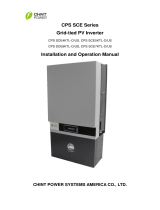
4. PV System
DC Switchboard
PV Generator
AC Switchboard
Public Grid
PV Inverter
A typical PV system contains:
1. PV Generator: Receive sunlight and generate DC power
2. DC Switchboard: Links between PV panels and PV inverter, include of DC
switch and surge protection
3. Inverter's DC Switch: PV Inverter with DC Switch
4. PV Inverter: Converts DC power by PV panels to AC output power for public
grid
5. AC Switchboard: Links between PV inverter and public grid
6. Public Grid: Provides utility for homes


10
6. Installation
PV-3000N-V/PV-5000W-V
Item
Description
Ⓐ
Inverter
Ⓑ
Mounting bracket kit
Ⓒ
User manual
Ⓓ
M4 flat screws × 8, used for mounting bracket
Ⓔ
Plastic anchors & screws × 3. Used to install
mounting bracket on wall
Ⓕ
EMI core(s) for Ethernet cable(s)
PV-3000N-V: Circular EMI cores × 2
PV-5000W-V: Clip-on EMI core × 1
Ⓐ
Ⓑ
Ⓒ
Ⓓ
Ⓔ
Ⓕ
*


13
6.2 Choosing Proper Installation Site
Avoid exposing the inverter in direct sunlight or to rain.
Mount the inverter in vertical direction; tilt or horizontal mounting should be
avoided.
Mounting
Surface
OK or NO
Concrete
OK
Metal
OK
Stone
OK
Plastics/Acrylic
No
Wood
No
Direct Sunlight
Direct Rain
Visible Level


15
6.4 Mounting Procedure
Dimensions of Bracket
The bracket is used to support inverter on wall. Refer to the recommendations
below to complete mounting.
Assembling Bracket
Before fixing on wall, assemble the bracket as below. (use M4 flat Screws x 4) item
Ⓓ of accessory kit.
PV-3000N-V
PV-5000W-V & PV-5000W-HV

16
Mounting Bracket
1. Place the assembled bracket on
where the inverter will be installed.
Make proper drill holes and mount
the assembled bracket with screws
from accessory kit. (use item Ⓔ to
install mounting bracket on wall).
2. For safe and firm mounting, make at
least 3 drill holes in a triangular
manner as demonstrated on right.
3. Use Ⓔ item (torque: 1.0-1.2Nm) to
install mounting bracket on wall.
Attaching Inverter
1. Lift inverter slightly higher than
bracket; Make sure all fixing points
on back are at correct positions.
2. Attach inverter on bracket.
3. Hang inverter on bracket slowly.
Checking
1. All supporting points are firm.
2. Lock caps are tightened with
screws.
3. Inverter is well installed and
secured on wall.
③


18
Overview of Connection Area
1. Cable Gland M25/M32 (AC cables)
2. Cable Gland M25 (Ethernet/RS485/RCR cables)
3. AC terminal block
4. RS485 terminal
5. RS485 terminal resistor switch
6. RS485 address selector
7. RJ45 port for Internet access
8. Ripple Control receiver (RCR) terminal
9. USB socket
PV-3000N-V/PV-5000W-HV
PV-5000W-V
①
②
①
②
⑨
⑨
③
③
④
④
⑤
⑤
⑥
⑥
⑦
⑦
⑧
⑧

19
AC Wiring
1. Prepare cables as recommended below
Cross
Section
(mm2)
Maximum Length for 1% Loss (M)
PV-3000N-V
PV-5000W-V
PV-5000W-HV
1.5
6
Not proper
Not proper
2.5
9
5
5
4
14
8
8
6
19
13
13
10
Not Proper
21
21
Table above is based on single-core copper wires with maximum
temperature rise of 60°C. The following factors should be taken into
account when it comes to actual wiring: Ambient temperature, Wiring
nearby and Cooling.
Please follow local standards if figures above are different from.
2. Remove strip insulation ~ 7 mm for PV-3000N-V
Remove strip insulation ~ 8 mm for PV-5000W-V/PV-5000W-HV
PV-3000N-V
PV-5000W-V/PV-5000W-HV
Note on AC Circuit Breakers
For safety purposes, place an independent circuit breaker
between inverter and grid BEFORE all connections. Make sure
inverter will be safely disconnected from the grid in all
circumstances.
It is recommended to use certified 250V/20A (PV-3000N-V) or
250V/30A (PV-5000W-V & PV-5000W-HV) circuit breakers only.
6mm2 max.
7mm
10mm2 max.
8mm
/