
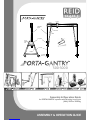
4. Adjustable
upright
Height
Adjusting
bolts
6. Trap Plate
1. “A” Frame
9. Strut
10. Cheek Plate
4. PG Toolkit
2. Beam
3. Trolley
8. Lockable
castors
7. Leg Brace
ASSEMBLY & OPERATION GUIDE
500-3000
2OOO1
LIGHTWEIGHT PORTABLE SAFE
Assembly & Operation Guide
for PORTA-GANTRY systems with Working Load Limit
(WLL) 500 to 3000kg

CONTENTS
INTRODUCTION
CORRECT OPERATION:
• Inspection prior to initial operation
• Inspection before starting work
• Maximum capacity
• Notes for correct usage
• Danger zones
• Attaching the load
• Temperature range
• Regulations
• Maintenance/Repair
• Inspection/Maintenance
• Regular Inspections
ASSEMBLY INSTRUCTIONS
VARIANTS & OPTIONS
• Wind Up Jack Legs
• Ratchet System
• Customised configurations
• PG5000

3
LIGHTWEIGHT PORTABLE SAFE
500-3000
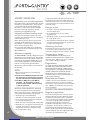
INTRODUCTION
All users must read these operating instructions
carefully prior to the initial operation. These
instructions are intended to acquaint the user
with the machine/hoist and enable him/her to
use it to the full extent of its intended capabilities.
The operating instructions contain important
information on how to handle the gantry in
a safe, correct and economic way. Acting in
accordance with these instructions helps to
avoid dangers, reduce repair costs and down
time and to increase the reliability and lifetime
of the gantry frame.
Anyone involved in doing any of the following work
with the gantry frame must read the operation
instructions and act accordingly:
• operation, including preparation, trouble
shooting during operation and cleaning
• maintenance, inspection, repair
• transport
Apart from the operating guide, health &
safety and accident prevention act valid for
the respective country and area where the
gantry frame is used, the commonly accepted
regulations for safe and professional work must
be adhered to.
N.B. This document should form an element of the
overriding Risk Assessment and Method Statement
required for each lift.

www.reidlifting.com
4
500 -
3000Kg
WLL
92-294Kg
flatpack
1-4
People
500-3000
CORRECT OPERATION
Inspection prior to initial operation:
Each gantry frame must be inspected prior to initial
operation by a competent person. The inspection
is visual and functional and shall establish that
the A frame is safe and has not been damaged
by incorrect assembly, transport or storage.
Inspections are instigated by the user.
Inspection before starting work:
The inspection procedure requires that a valid
inspection/test certificate has been submitted to
and checked by the user.
Before starting work inspect the gantry frame
assembly and all load-bearing components for
visual defects. Furthermore, test the trolley for
free movement along the beam.
Ensure that the overall WLL limit is adhered to
– following the necessary Risk Assessment and
Method Statement.
Maximum capacity:
The PORTA-GANTRY assembly is designed to lift and
lower loads up to the related capacity. The capacity
indicated on the frame is the maximum weight load
limit (WLL) or safe working load (SWL) which must
not be exceeded (definition is country dependent).
Each lift must be properly planned and the
weight of the load to be lifted must be known by
the operator.
NOTE:
1 We recommend the use of a load-sensing
device on all lifts.
2. The Gantry should NOT be moved under load.
Any deviation from this should be supported
by a risk assessment and method statement.
3. The WLL (or SWL) rating must NOT be
exceeded – risk assessment & method
statement must consider additional loading
in “wet lift” situations
NOTES FOR CORRECT USAGE
Do not throw the gantry frame or its components
down or stack items on top of it. Always place properly
on the ground avoiding damage to the equipment.
• Assemble only as instructed above.
• The beam must be horizontal prior to any lift
• Do not use the gantry frame if the trolley does
not run freely along the beam.
•
Attach hoist only to the lifting point on the trolley.
• Avoid side pull. Lift only when load chain(s) form
a straight and vertical line between load and
lifting attachment point on the gantry trolley.
• Do not allow load to swing.
•
Only raise and lower loads when foot brakes are ‘on’.
The gantry is not to be moved under load except
when a Competent Person or authority approves
a risk assessment and a method statement for a
particular reason.
Danger zones:
• Do not lift or transport loads while personnel
are in the danger zone.
• Do not allow personnel to pass under a
suspended load.
• After lifting, a load must not be left unattended
for a long period of time.
• Start moving the load down the beam only after
it has been attached correctly and all personnel
are clear of the danger zone.
Attaching the load:
The operator must ensure that the hoist is attached
in a manner that does not expose him or other
personnel to danger by the hoist, chain(s) or the load.
Temperature range:
The PORTA-GANTRY frame assembly can be
operated in ambient temperatures between -20°C
and +50° (-4°F to 122°F). Consult your supplier in
case of extreme working conditions.
Regulations:
The Supply of Machinery (Safety) Regulations (2008)
(S.I. 2008/1597), The Provision and Use of Work
Equipment Regulations 1998 (S.I. 1998 No. 2306),
The Lifting Operations and Lifting Equipment Regulations
1998 (S.I. 1998 No. 2307), Machinery Directive
2006/42/EC and/or safety regulations of the
respective country for using manual lifting equipment
must be strictly adhered to.
Maintenance/Repair:
In order to ensure correct operation not only the
operations instructions, but also the conditions
for inspection and maintenance must be complied
with. If defects are found stop using the gantry
frame immediately.
INSPECTION/MAINTENANCE:
Regular inspections:
To ensure that the gantry frame remains in safe
working order they are to be subjected to regular
inspections by a competent person. Inspections
are to be annual unless adverse working conditions
or profile of use dictate shorter periods. The
components of the gantry frame are to be
inspected for damage, wear, corrosion or other
irregularities. To check for worn parts it may
be necessary to disassemble the gantry frame.
Repairs should only be carried out by an approved
specialist workshop that uses original spare parts.
Inspections are instigated by the user.

Tel: +44 (0) 1291 620796 enquiries@reidlifting.com
5
LIGHTWEIGHT PORTABLE SAFE
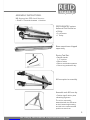
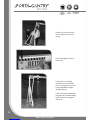
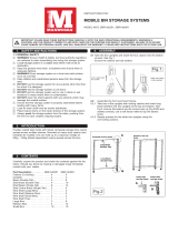
PORTA-GANTRY system
delivered Flat Packed on
a Pallet:
• 2 x A-Frames
• 1 Trolley
Beam sometimes shipped
separately
Assemble each A-Frame by:
• Position legs & bolt in place
• Attaching leg brace
The unit is most easily
assembled with the A-Frames
at their lowest height setting
and this is the recommended
position to start from.
A-Frame prior to assembly
Gantry Tool Set:
• Ratchet handle
1/2” sq drive
• 24mm socket
• 24mm combination spanner
• 14mm long series allen key
ASSEMBLY INSTRUCTIONS:
NB: Appropriate PPE should be worn
• Gloves • Protective footwear • Hard hat

www.reidlifting.com
6
500 -
3000Kg
WLL
92-294Kg
flatpack
1-4
People
500-3000
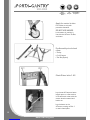
Apply the castor brakes
Put brakes on only with
protective footwear
DO NOT USE HANDS
Lock casters in position in
line with the A-Frame Tie Bar,
as shown:
Lay the two A-Frames a beam
length apart on a flat surface
in line with each other with the
castor wheels outward and
brakes on.
Lay the beam on the
A-Frames, resting on Bolt 1
on each cheek plate
Cheek Plates bolts 1 & 2
Pre Assembly visual check
• Beam
• Trolley
• 2 x A-Frames
• Tool Set (Option)

Tel: +44 (0) 1291 620796 enquiries@reidlifting.com
7
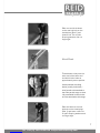
Offer one end of the beam
to the rear bolt-hole on the
cheek-plate (Bolt 1) and
insert a bolt. Put on plain
& spring washers and nut,
finger tight.
Thread beam trolley over the
other end of the beam and
lock with friction brake at
approximately centre position.
Assess whether the lifting
device (usually chain block /
hoist) needs to be attached to
the trolley at this stage or when
fully assembled. Heavier hoists
are best attached at this stage.
Offer the beam to the rear
bolt-hole on the cheek-plate
(Bolt 1) and insert a bolt. Put
on plain & spring washers and
nut finger tight.
Visual Check
LIGHTWEIGHT PORTABLE SAFE

www.reidlifting.com
500 -
3000Kg
WLL
92-294Kg
flatpack
1-4
People
500-3000
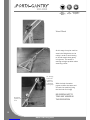
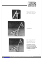
With the help of another
person, scissor the beam and
A-Frame into position (using
the first bolt as a hinge)
BE CAREFUL NOT TO
TRAP ANY HANDS IN
THIS OPERATION
At this stage it may be useful to
attach the lifting device to the
trolley in order to avoid having
to lift and attach when gantry
is fully erect. This avoids a
working at height problem when
attaching a hoist.
Lift - Keeping
hands clear
of potential
“Pinch” area
marked with
warning tape
Chain Hoist
opposite end
to lift
Visual Check
8

Tel: +44 (0) 1291 620796 enquiries@reidlifting.com
Insert the second bolt into
the cheek-plate. Tighten both
bolts. (Do not over tighten)
Move trolley to other end of
beam, opposite to the end
to be raised, and secure by
tightening the trolley knob.
(For additional safety whilst
the beam is at such an angle a
spare bolt can be temporarily
be placed in an adjustment point
on the beam to prevent the
trolley slipping down the beam)
Visual Check
LIGHTWEIGHT PORTABLE SAFE
9

www.reidlifting.com
10
500 -
3000Kg
WLL
92-294Kg
flatpack
1-4
People
500-3000
Repeat the scissor activity
at the opposite end of the
gantry.
Insert and tighten the final
beam bolt.
If the hoist is not already
attached to the suspension
point on the trolley, do so now
(using stepladder if height
setting requires).
If this is not safe, disassemble
the gantry and re-start adding
the hoist prior to raising the
A-Frames.

Tel: +44 (0) 1291 620796 enquiries@reidlifting.com
11
The gantry is now erect at its
lowest height setting.
Tighten all bolts to
27 Nm (20 ft lbs)
(If raising the beam height
– leave the two height
adjustment bolts loose on
each upright – see next image)
Release trolley brake and
wheel brakes to position the
structure over the lifting point.
Decide on the height required
(always using the lowest
setting for the work in hand).
Adjust the upright position
at one A-Frame (a 2 man
operation – one on the bolts
and one on the upright) by
removing 2xUpright securing
bolts, moving the upright to
the appropriate setting by
lifting from the strut handle.
Re-secure with bolts, nuts &
washers (Do not over tighten).
Repeat the height adjustment
at the opposite end.
N.B. Ensure the beam is
horizontal prior to any lift –
see Method Statement.
Beam height
adjustment
bolts
(2 bolts on
each upright)
LIGHTWEIGHT PORTABLE SAFE

www.reidlifting.com
500 -
3000Kg
WLL
92-294Kg
flatpack
1-4
People
500-3000
VARIANTS & OPTIONS:
• Wind Up Jack Legs
• Ratchet Beam Elevation System:
• Customised congurations
• PG5000
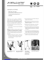
Wind Up Jack Leg Option (WUJL):
WUJL option may be fitted to the gantry – if so this
gives fine adjustment in the height setting (300mm
total lift on the uprights) and gives independent foot
adjustment, particularly useful on uneven ground.
If the windup jack legs are fitted the following points
must be observed:
1. Check whether the castors fitted are Load Rated
(or Pneumatic).
Note: When ‘all-terrain’, pneumatic castors that are
not rated for lifting, the WUJL system must always
be applied prior to performing any lift. If load rated
castors are fitted the operator can choose whether
the castors or WUJL take the load on each foot of
the gantry.
2. When transporting over ground or manoeuvring
the gantry, into position, always have the stands
in the ‘parked’ position as in figure.1 below or
remove if required.
3. Position the gantry for the lift before setting the
heights with the stand-off.
4. Before lifting ensure all jacks are in the correct
lifting position and are secured with locking pins
and clips as in figure.2.
5. Manually raise each leg/castor in turn and set
the height by rotating jack handle clockwise
6. Having set the adjustment of all four legs, stand
back from the gantry and ensure that the gantry
uprights are vertical and the beam is horizontal
as in figure.3.
7. If the ground that the load spreading feet are on
is soft and likely to sink when the load applied put
boards under the feet to spread the load further.
8.
Having performed the lifting operations, put the
stands in the ‘park’ position and disassemble.
Fig.1 Wind Up Jack Leg in
‘parked’ position
Fig.2 Jacks secured with
locking pins and clips
Fig.3 Wind Up
Jack Leg system
in place, used with
pneumatic ‘all-
terrain’ castors.
Fig. 4 Example application
12

Tel: +44 (0) 1291 620796 enquiries@reidlifting.com
LIGHTWEIGHT PORTABLE SAFE
Beam Height Adjustment using
Ratchet System option:
(Two Person Operation Recommended – one on
the bolts and one on the upright)
Always wear gloves when using this item.
1. Decide on the height required (always use the
lowest setting for the work in hand).
2. Remove 2-off upright bolts.
3. Operate ratchet to adjust height to required
setting, ensuring that the bolt holes are
aligned.
4. Re-secure with 2-off upright bolts, nuts and
washers.
5.
Repeat steps 2-4 on the second A-Frame,
ensuring that both A-Frames finish at the
same height.
6. Check all bolts on the gantry are secure.
7.
If the hoist is not already attached to the
suspension point on the trolley, do so now (using
stepladder if height setting requires). If this is
not safe, disassemble gantry and re-start from
page 8 of the Gantry Assembly Instructions.
Customised configurations:
For customised systems additional assembly and
operation information will be provided as required
PORTA-GANTRY 5000:
Unique lightweight, portable gantry system with
WLL to 5000kg
See separate Assembly & Operating Guide
E&OE
13

www.reidlifting.com
14
500 -
3000Kg
WLL
92-294Kg
flatpack
1-4
People
500-3000
A
B
D
E
F
C
G
85
Bolts, nuts & washers
Cheek plate
Adjustable
upright
“Trap” plate Strut
Trolley
Lockable
castors
Leg Brace
Leg
Patent Application Numbers: 0722596.4, GB 2457875A, 0803120.5 International Patent Application Numbers: PCT/EP2008/065675, PCT/GB2009/000467
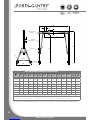
REID PORTA-GANTRY STANDARD UNIT DATA SHEET
Overall
Beam
Length
Span
Adjustment
Increment
Max
Working
Span
Max Height
to Lifting
Eye
Height
Adjustment
Increment
Min Height
to Lifting
Eye
Max Height
to Top of
Beam
Max Width
Across
Legs
Assembled
Weight (Ex
Trolley)
Beam
Weight
A Frame
Weight
ABC D EF G
WLL Kg /
Frame Size mm mm mm mm mm mm mm mm Kg Kg Kg Kg
500 (S) 2500 200 1580 2361 150 1611 2678 1220 85 19 33 192
1000 (M) 3920 200 3000 2854 150 2104 3171 1429 109 29 40 2 116
2000 (I) 4570 200 3650 3198 200 2198 3514 1726 125 33 46 2 132
3000 (T) 4570 200 3650 4089 200 2889 4405 2011 205 43 82 3 212
5000*(I) 4570 200 3650 3168 200 2168 3616 1726 265 71 97** 3/4 275
5000*(T) 4570 200 3650 4040 200 2840 4485 2011 284 71 106** 3/4 294
All WLL ratings can be produced in each standard frame size Custom spans, height and Working Load Limits (WLL) on application.
*N.B. PG5000 beam depth (250mm), trolley depth (570mm) & trolley top above beam (125mm) are larger than the standard beam depth (152mm), trolley depth
(385mm) and trolley top above beam (85mm)
** This weight includes the stabiliser leg option Please note that dimensions may vary marginally NB. No leg brace fitted on ‘S’ systems

Tel: +44 (0) 1291 620796 enquiries@reidlifting.com
15
Quality and Safety are key themes throughout this
document and the REID Lifting ethos.
It is with this in mind that we have undertaken
external accreditations to ensure we stay focused
on what is important to our clients and users and
ahead of market trends and developments in Safety
and Quality systems.
REID Lifting has been successfully audited by Lloyds
Register (LRQA) for approval of its Integrated
Management System combining quality systems
management, environmental issues and the Health
and Safety practices within the company.
REID Lifting holds the following certifications:
• ISO 9001 - Specifies requirements for a quality
management system for any organisation that
needs to demonstrate its ability to consistently
provide product that meets customer and
applicable regulatory requirements and aims to
enhance customer satisfaction.
• ISO 14001 - Specifies the requirements for
implementing environmental management
systems throughout all areas of the company.
• OHSAS 18001 - Occupational Health and Safety
Managements Systems.
• LEEA Membership - REID Lifting Ltd is a full
member of the Lifting Equipment Engineers
Association (membership 000897). REID Lifting
conforms to the main aims of the Association
which is to achieve the highest standards of
quality and integrity in the operations of members.
Their entry qualifications are demanding and
strictly enforced through technical audits based
on the Technical Requirements for Members.
Conformité Européenne (CE)
REID Lifting’s products have been designed, tested
and approved (as appropriate) by the Conformité
Européenne (French for European Conformity).
This certifies that REID Lifting’s products meet the
demands of the European Directives regarding
Health and Safety requirements.
The Queen’s Award for
Enterprise Innovation:
REID Lifting Ltd has been awarded this prestigious
award for innovative design and development of
lightweight, portable and safe lifting solutions.
TESTING
Testing and Technical File review are integral parts
of our design and manufacturing process – to
externally verify the products, where appropriate,
using government approved Notified Bodies.
All REID Lifting products are type tested at NAMAS
accredited laboratories and every individual system
is tested to 150% of WLL rating.
Full product design & development Technical Files
are available for inspection.
PRODUCT IPR
Design Rights apply to all REID Lifting Ltd products
REID PATENTS in place, or pending, for:
• PORTA-GANTRY
• T-DAVIT
• SNAPPER
All product names are Trade Marks of REID Lifting Ltd:
• PORTA-GANTRY
• PORTA-DAVIT
• PORTA-BASE
• T-DAVIT
• PORTA-QUAD
• SNAPPER
• PORTA-LIFTER Manhole Lifter
ACCREDITATIONS
QUALITY & SAFETY
LIGHTWEIGHT PORTABLE SAFE

All information herein is copyright protected by Reid Lifting Ltd. All company and product names are Trade Mark and
Trade Name protected and all REID Product IPR is protected under Patents, Patents Pending and/or Design Rights.
Further information and support can be found
on our website www.reidlifting.com
WHAT’S NEXT
N.B. This document should form an element of the
overriding Risk Assessment and Method Statement
required for each lift.
EMAIL US
CALL US
+44 (0)1291 620796
WEB
www.reidlifting.com
Reid Lifting Limited
Unit 1 Severnlink
Newhouse Farm Industrial Estate
Chepstow
Monmouthshire NP16 6UN
Tel: +44 (0)1291 620796
Fax: +44 (0)1291 626490
Reid Lifting France
16 Quater
Avenue Martyrs de la Resistance
56250
Elven, France
Tel: +33 (0)297 53 32 99
Fax: +33 (0)297 53 04 86
BPF Distributors & Pumps Limited
Industrial Estate, Killough Road,
Downpatrick, Co. Down BT30 6LJ
NI
Tel: +44 (0)28 4461 5777
Fax: +44 (0)28 4461 4250
ROI
Tel: +353 (0)1 478 0665
Fax: +353 (0)1 478 0678
[email protected] & www.bpf-ltd.com
KAMAB Lyftsystem AB
Box 74, Rallarvägen 15
184 21 Åkersberga, Sweden
Tel: +46 (0)8540 69180
Fax: +46 (0)8540 60566
www.kamab.nu
Thern, Inc.
5712 Industrial Park Road
PO Box 347
Winona, MN 55987
USA
Phone: 507.454.2996
Toll Free: 800.843.7648
Fax: 507.454.5282
• Systems are type tested
at NAMAS accredited
laboratories
• Every individual system is
tested to 150% of WLL
rating prior to shipment
• Full product design &
development Technical
Files are available for
inspection
• Lifting Equipment
Engineers Association
(LEEA) full membership
• ISO9001 Quality
Management Systems
accreditation
• ISO14001 accreditation
environment
management systems
and standards
• OHSAS18001
Occupational Health and
Safety Management
accreditation
• Certification of products
by relevant recognised
bodies from sockets to
systems
• Safe assembly, use and
maintenance manuals
and training are available
for all systems
REID Lifting – the best night’s
sleep in the lifting industry
Printed using environment friendly processes and materials PGOM500-3000/EN/V7/11/03
Designed and produced by Horizon Digital Media Ltd www.horizondml.co.uk
LIGHTWEIGHT PORTABLE SAFE
-
 1
1
-
 2
2
-
 3
3
-
 4
4
-
 5
5
-
 6
6
-
 7
7
-
 8
8
-
 9
9
-
 10
10
-
 11
11
-
 12
12
-
 13
13
-
 14
14
-
 15
15
-
 16
16


REID LIFTING SNAPPER Assembly & Operation Manual
- Type
- Assembly & Operation Manual
- This manual is also suitable for
Ask a question and I''ll find the answer in the document
Finding information in a document is now easier with AI
Related papers

Other documents
-
 Maxworks STST2350 User manual
-
Sealey SG2000W Operating instructions
-
Sealey AP890M User manual
-
Vestil AHS-8-10-12 User guide
-
-
Pittsburgh Automotive 62510 Owner's manual
-
-
-
Harbor Freight Tools 69513 User manual
-
Invacare Robin Installation And Technical Manual
