Page is loading ...

ASSEMBLY VIDEO
www.reidlifting.com
Assembly & Operation

No. 1 in lightweight, portable, safe lifting solutions
2
CONTENTS
INTRODUCTION
CORRECT OPERATION
• Intended Use
• Inspection Prior to Initial Operation
• Inspection Before Starting Work
• Maximum Capacity
NOTES FOR CORRECT USAGE
• Warning
• Attaching the Load
• Temperature Range
• Regulations
INSPECTION/MAINTENANCE
• Regular Inspections
• Maintenance/Repair
• Storage and Transportation
• Marking
ATEX
• ATEX - Classification
• ATEX - Identification
• ATEX - Spark Formation
• ATEX - Static Electricity
• ATEX - Inspection, Maintenance & Repair
IRATA
LANGUAGE
ASSEMBLY INSTRUCTIONS
• Mechanical Aid Assembly
• Manual Assembly
• Beam Height Adjustment
• A-Frames with Geared Handwheel
• A-Frame with Ratchet System
• Medium or Small A-Frame with no gearing fitted
VARIANTS AND OPTIONS
• A-Frame and Stabiliser Leg
• Manoeuvring A-Frame using Stabilising Leg in
Wheelbarrow Configuration
• Changing Stabilising Leg from Wheelbarrow to
Vertical Configuration
• Changing Stabilising Leg from Vertical to
Wheelbarrow Configuration
• Manoeuvring A-Frame using Stabilising Leg in
Vertical Configuration
• Wind Up Jack Legs Option (WUJL)
• WUJL Inspection / Maintenance
• Easy Conversion to Winched Configuration
• Customised Configurations
PORTA-GANTRY RANGE
• Beam Height Adjustment
• Beam Options
• Detailed Dimensions
• PO RTA -GANTRY 500-3000
• PO RTA -GANTRY RAPIDE
QUALITY & SAFETY
• Accreditations
TESTING
PRODUCT IPR
INSPECTION RECORD

Tel: +44 (0)1291 620796 www.reidlifting.com
INTRODUCTION
All users must read these operating instructions
carefully prior to the initial operation. These
instructions are intended to acquaint the user with the
machine/hoist and enable him/her to use it to the full
extent of its intended capabilities.
The operating instructions contain important
information on how to handle the gantry in a safe,
correct and economic way. Acting in accordance with
these instructions helps to avoid dangers, reduce
repair costs and down time and to increase the
reliability and lifetime of the gantry.
Anyone involved in doing any of the following work with
the gantry must read the operation instructions and
act accordingly:
• Operation, including preparation, troubleshooting
during operation and cleaning
• Maintenance, inspection, repair
• Tran spor t
Apart from the operating guide, health & safety
and accident prevention act valid for the respective
country and area where the gantry frame is used,
the commonly accepted regulations for safe and
professional work must be adhered to.
It is incumbent on the user or instigator of work with
the equipment that all users have suitable medical and
physical capabilities. Likewise the competent person
should ensure there is a rescue plan in place in the
event of an emergency that could occur during
the work.
N.B. This document should form an element of the
overriding Risk Assessment and Method Statement
required for each lift.

No. 1 in lightweight, portable, safe lifting solutions
4
CORRECT OPERATION
Intended Use
The PO RTA-GANTRY is intended to be used for the
lifting of goods or the lifting of persons, or for providing
a safety anchor for the prevention of falls.
N.B. We recommend that the device is dedicated to
either goods or personnel use and where reasonably
practicable to avoid using the structure for both.
PO RTA-GANTRYs are suitable for Rope Access and
have been tested to 15KN static load as per test
requirements of IRATA International Code of Practice
(ICOP).
Inspection Prior to Initial Operation
Each P ORTA-GANTRY must be inspected prior to initial
operation by a competent person. The inspection
is visual and functional and shall establish that the
structure is safe and has not been damaged by correct
assembly, transport or storage. Inspections are
instigated by the user.
Inspection Before Starting Work
The inspection procedure requires that a valid
inspection/test certificate has been submitted to and
checked by the user.
Before starting work inspect the gantry assembly and
all load-bearing components for visual defects. Check
the integrity of all profiles for denting and bolt holes for
wear and elongation. Furthermore, test the trolley for
free movement along the beam.
Ensure that the overall working load limit (WLL) is
adhered to – following the necessary Risk Assessment
and Method Statement.
Maximum Capacity
The
PO RTA-GANTRY
is designed to lift and lower loads
up to its rated capacity. The capacity indicated on the
frame is the maximum working load limit (WLL) or
safe working load (SWL) which must not be exceeded
(definition is country dependent).
When being used as a personnel lifting anchor the
user must use a body harness and retractable de
vice
or shock absorber to EN355, ANSI Z359.6-09 or CSA
Z259.16-04 that limits the maximum allowed fo
rce
(M.A.F.) to 6kN. Winches used with the
PO RTA-GANTRY
should comply to EN1496:2017 or equivalent.
Only ONE person/load may be attached to ONE trolley
in accordance with the WLLs.
The gantry has an up-rated capacity for personnel
positioning. This is when the structure is to be used
as an anchor for lifting persons that have a suitably
low chance of falling through a free distance and
only carried out following a comprehensive risk
assessment.
While the
PO RTA-GANTRY
has the capacities stated
in the table below, it is only one part of a fall arrest
system which is only as strong as its lowest rated
component. Each lift must be properly planned and
all weights clearly known along with the WLLs and
constraints of all fall arrest system devices.
The capabilities stated in the table below are only
applicable to standard range PORTA-GANTRY systems
with a 5000kg working load limit. Bespoke versions
of the gantry are available tailored to specific lifting
needs. If unsure about your system consult serial
labels, information filled in on page 27 or consult your
supplier. A custom gantry is designated by a product
number ending with a “C” found on the serial label
attached to each A-frame and the beam. For custom
designed gantries please contact your supplier for
appropriate rating and capabilities.
In the event of simultaneous goods and personnel
combined lifting or when being used as a fall arrest
system in sub-zero AND wet conditions contact the
supplier as capacities may be reduced.
The
PO RTA-GANTRY
has different ratings depending
upon the application as detailed in the table below:
Application Capacity
Goods [kg] 5000
Fall Arrest* 5 persons
Max. Combined Personnel
Lifting Capacity [kg]
2000
*Only Applicable to PO RTA -GANTRY systems being
used in accordance with PD CEN/TS 16415:2013.
When being used in accordance with EN795:2012,
the structure shall be limited to a maximum of one
user in fall arrest.

Tel: +44 (0)1291 620796 www.reidlifting.com
NOTES FOR CORRECT USAGE
• We recommend the use of load-sensing or overload
protection devices on all lifts
• The Risk Assessment and Method Statement must
consider additional loading resulting from any “wet
lift” situations
• Ensure suitable winches and connection plates are
used for all applications
• Due care and attention should be practiced
when transporting and storing the gantry to
avoid damage
• Assemble only as instructed (ensure all bolts are
present and fitted correctly as per instructions).
• We recommend that gloves should be worn when
using this equipment
• Set up the gantry at a safe distance from the hazard
and subsequently move the structure into place
• The beam must be horizontal prior to any lift and
A-frames vertical and parallel to each other
• Do not use the gantry if the trolley does not run
freely along the beam
• Attach hoist only to the lifting point on the trolley
• Avoid side pull. Lowering and lifting should only be
carried out when the load chain/lifeline form a
straight and vertical line between the load and lifting
attachment point on the trolley
• Do not allow load to swing
• When lifting keep the load low to the ground.
• NEVER walk away from structure whilst connected
to the equipment i.e. connected by a fall arrest block
or winch
• Only raise and lower loads when CASTOR BRAKES
are ENGAGED
• When using the gantry as a fall arrest anchor the
required clearance of the fall arrest device should be
considered - refer to device’s Assembly & Operation
manual and consider the height adjustment on the
gantry
• Before the gantry is used consideration must
be given to the potential effects of the lifelines
over sharp edges, chemical reagents, electrical
conductivity, cutting, abrasion, climatic exposure and
the effect of offset forces as a result of pendulum falls
• The gantry is not to be moved under load except
when a Competent Person or authority approves
a Risk Assessment and a Method Statement for a
particular reason
• To ensure stability of the structure, the operating
span of the beam must be equal to or greater than
the distance between the castors on the A-Frame
Warning
• The equipment shall not be used outside its limitations,
or for any purpose other than that for which it is intended
• When winching only one lifeline should be used with
each sheave and they should never cross paths with
each other
• Do not lift or transport loads while personnel are in
the danger zone
• Do not allow personnel to pass under a suspended load
• When gantry is used with multiple persons attached
working procedures should dictate that individual
lifelines do not cross and become tangled
• It is NOT recommended to mix the use of the gantry
with personnel and goods lifting concurrently
• Never leave a suspended load unattended
• Start moving the load along the beam only after it has
been attached correctly and all personnel are clear of
the danger zone
• Be aware of hazards when setting up/folding down,
eg. hands/fingers trapped in rotating parts
• It is essential for safety that the PO RTA -GANTRY is
withdrawn from use immediately should:
1. Any doubt arise about its condition for safe use
Or
2. It has been used to arrest a fall and not be used
again until confirmed in writing by a competent
person that it is acceptable to do so
• Be aware of adverse weather, high, gusty or
moderate/strong breeze conditions could impose
horizontal loads, potentially affecting the stability of
the structure. If weather conditions are impacting
lifting operations, work should be stopped and gantry

No. 1 in lightweight, portable, safe lifting solutions
6
It is recommended that once inspected the device is
marked with the date of next inspection.
Inspections are instigated by the user.
If detailed information is required on inspection
and test criteria, please refer to your supplier’s
technical department.
Please refer to page 27 for the equipment
Inspection Record.
If using the Gantry in explosive atmospheres see
additional section titled ATEX.
Maintenance/Repair
In order to ensure correct operation not only the
operations instructions, but also the conditions for
inspection and maintenance must be complied with.
If defects are found stop using the PO RTA -GANTRY
immediately.
No alterations or additions to the equipment should be
made without the written consent of the manufacturer.
Any repair shall only be carried out in accordance with
the manufacturer’s procedures.
It is recommended to maintain the equipment in a clean
and dry manner. Cleaning is suggested using a sponge
or cloth with warm, soapy water (using diluted domestic
washing up liquid), rinsing and allowing to dry.
Storage and Transportation
When transporting the components the user must take
note of the manual handling considerations.
Do not throw the gantry or its components down or
stack items on top of it. Always place properly on the
ground avoiding damage to the equipment.
Marking
The serial labels indicate:
• The product identification number
• The product’s unique serial number
• The goods’ WLL of the device
• The year of manufacture
• The standards to which the device is approved
• The ATEX rating of the product (if applicable) -
see ATEX section
should be disassembled. If disassembling is not
possible, the gantry should be tied to a rigid
structure to avoid overturn
Attaching the Load
The operator must ensure that the hoist is attached
in a manner that does not expose him or other
personnel to danger by the hoist, chain(s) or the load.
Temperature Range
The
PO RTA -GANTRY
can be operated in ambient dry
temperatures between -20° and +55°C (-4°F to 131°F).
Consult your supplier in case of extreme working
conditions.
If used in sub-zero and wet conditions,
fall arrest appliances characteristics may change.
Regulations
The
PO RTA -GANTRY
complies with the following
regulations:
ATEX Directive - 2014/34/EU, PPE Regulation (EU)
2016/425, Machinery Directive 2006/42/EC, The
Provision and Use of Work Equipment Regulations
1998 (S.I. 1998 No. 2306), The Lifting Operations and
Lifting Equipment Regulations 1998 (S.I. 1998 No.
2307). In conformity with AS/NZS 5532:2013.
The safety regulations of the respective country
for using manual lifting equipment must be strictly
adhered to. EN795:2012, PD CEN/TS 16415:2013,
ANSI Z359.18 and CSAZ259.16-15.
INSPECTION/MAINTENANCE
Regular Inspections
To ensure that the gantry frame remains in safe
working order it must be subjected to thorough
periodic inspections by a competent person.
Inspections are to be 6 monthly for personnel lifting
and 12 monthly for goods only unless adverse
working conditions or profile of use dictate shorter
periods. The components of the gantry frame are to
be inspected for damage, wear, corrosion or other
irregularities. To check for worn parts it may be
necessary to disassemble the gantry frame. Particular
attention should be paid to the areas of the structure
described under Inspection Prior to Initial Operation.
Repairs should only be carried out by an approved
specialist workshop that uses original spare parts.

Tel: +44 (0)1291 620796 www.reidlifting.com
• CE 0598: CE mark plus notified body number
(currently SGS) who are responsible for monitoring
REID Lifting’s quality control system in accordance
with Module D of the PPE Regulation (only
applicable when rated for the lifting of persons
otherwise CE just stated)
Read
Assembly & Operation instructions
PO RTA-GANTRY 5000kg
Assembly & Operation instructions
Risk Assessment
Please use this risk assessment as a
guide only, all customers must complete
their own method statement and risk
assessment to suit the environment in
which the equipment is being used
ATEX
This product has been designed for use in explosive
atmospheres. If the product is to be used in explosive
atmospheres then the following section must be
followed. Any different or exceeding use is considered
incorrect and REID Lifting Ltd will not accept any
responsibility for damages resulting from false
application. The risk is solely with the user. If the
product has been customised in any way then it may
not comply with standards and not be suitable for use
in explosive atmospheres. If this is the case then the
product will not have any of the below marking. If in
doubt contact your REID representative.
ATEX - Classification
As standard, the product meets the requirements
of Category 3 equipment for use in Zone 2 explosive
atmospheres, providing a normal level of protection
where mixtures of air and gases, vapours or mists or
by air/dusts mixtures are unlikely to occur or, if they
do occur, are likely to do so only infrequently and for a
short period only.
Or
The product can be supplied to meet the requirements
of Category 2 equipment for use in Zone 1 explosive
atmospheres, providing a high level of protection
where mixtures of air and gases, vapours or mists or by
air/dusts mixtures are likely to occur.
ATEX - Identification
In addition to the previous Marking section, the product
will have the following identification on the serial label:
As Standard for Zone 2 Environments:
II 3 GD T6
Identification for protection against explosions
II: Unit group II – non-mining application
3: Category 3 – Normal safety for use in Zone 2
GD: For use in gas (G) & dust (D) atmospheres
T6:Temperature class – Max 85°C
Or
As an Upgrade for use in Zone 1
Environments:
II 2 GD T6
Identification for protection against explosions
II: Unit group II – non-mining application
2: Category 2 – High safety for use in Zone 1
GD: For use in gas (G) & dust (D) atmospheres
T6:Temperature class – Max 85°C
ATEX - Spark Formation
Increased danger of ignition may emanate from
clashing of special material pairings. These are non
corrosion-resistant steel or cast iron against aluminium,
magnesium or pertinent alloys. This applies especially
in case of rust or surface rust. When assembling the
product and inserting fastening components they must
be clear of rust and debris of any kind. Care must be
taken to ensure the product is handled in a suitable
manner, is never thrown and always placed onto the
ground.
For Zone 1 and 2 applications, the height of the
PO RTA-GANTRY should NOT be adjusted using the
ratchet mechanism and/or geared wheel within the
said zone.

No. 1 in lightweight, portable, safe lifting solutions
8
REID recommend the use of corrosion resistant tools
when assembling the PORTA-GANTRY system to
prevent the possibility of any sparks.
For ATEX Zone 1 use, stainless steel castor brackets
are fitted to reduce the possibility of a spark.
ATEX - Static Electricity
For Zone 2 applications static electricity has been
identified as potential for build up leading to an
incendive spark. Although the risk of such ignition is
unlikely the gantry must be earthed during assembly
and use. This can be achieved by attaching a 4mm
earthing lead to a convenient location on metallic
parts of both the Gantry and Trolley.
In Zone 1 applications, for added explosion protection,
the gantry is fitted with anti-static trolley rollers,
stainless steel fasteners and therefore does not
need to be earthed. However, the effectiveness of
the conductivity during operation can be affected
by a dirty tread or other environmental influences
and therefore must be checked by the operator
periodically.
ATEX - Inspection, Maintenance
& Repair
If using the gantry in explosive atmospheres, in
addition to the Regular Inspection/Maintenance
information found on page 6, these additional
instructions should be followed.
Inspections shall be instigated by the user prior to
each use if used in a potentially explosive atmosphere.
Inspections and maintenance shall be carried out at a
safe distance away from an explosive atmosphere.
Special attention should be given to dust deposits on
the structure, especially in areas where the profiles
come into contact, and should be wiped clean and
care taken not to apply materials that could create
electrostatic charging. Additionally the bearings in
the trolley rollers and castors should be checked to
ensure they rotate freely.
The structure is predominantly constructed from
aluminium which will not rust. However there are
steel components used throughout. These are
the fasteners, castors, master-link, trolley rollers,
A-frame height adjustment gearing system (if fitted)
and the height adjustment ratchet (if fitted). Where
there is sign of any rust deposits on the aluminium
structure it should be wiped clean as above and where
there is sign of rust on a steel component then that
component should be removed from use and the
structure not used until a replacement is fitted.
IRATA
PO RTA-GANTRYs are suitable for Rope Access and
have been tested to 15KN static load as per test
requirements of IRATA International Code of Practice
(ICOP).
LANGUAGE
It is essential for the safety of the user that if this
product is re-sold outside the original country of
destination the reseller shall provide instructions
for use, maintenance, for periodic examination and
for repair in the language of the country in which the
product is to be used.

Tel: +44 (0)1291 620796 www.reidlifting.com
ASSEMBLY INSTRUCTIONS
Gloves Hard hatProtective footwear
N.B. Appropriate PPE should be worn:
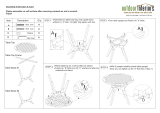
The PO RTA -GANTRY and its constituent components are described in the image below.
Leg
Lockable Castors
‘Trap’ Plate
Hockey Stick
Strut Handle
Strut
Leg Brace
Bolts, Nuts & Washers
Cheek Plate
Trolley
Beam
Adjustable Upright

No. 1 in lightweight, portable, safe lifting solutions
10
1. P O RTA-GANTRY system delivered flat packed on
a pallet:
• 2 x A-Frames
• 1 Tr o l le y
• (Stabiliser legs – Option)
• Beam (sometimes shipped separately)
2. Gantry Tool Set (supplied as an option):
• Ratchet handle 1/2” sq drive
• 24mm socket
• 24mm combination spanner
• 14mm long series allen key
• 14mm Hex key socket
4. Assemble each A-Frame by:
• Positioning legs and bolt in place
• Attaching leg brace
The unit is most easily assembled with the
A-Frames at their lowest height setting and this
is the recommended position to start from.
(A-Frame shown with Geared elevation and
Stabiliser leg attached)
3. A-Frame prior to assembly

Tel: +44 (0)1291 620796 www.reidlifting.com
8. Offer one end of the beam to the rear bolt-hole on
the cheek-plate (Bolt 1) and insert a bolt. Put on plain
and spring washers and nut, finger tight.
N.B. The gantry beam has adjustment holes to
narrow the footprint of the gantry. This is best
done when the gantry is assembled with 2 persons
sliding the A-frame inwards while 1-2 persons
steady the gantry by holding the beam – this will
require the use of a step ladder. If this process is
required to be carried out often then an upgrade to
‘lobed cheek plates’ can be purchased which allows
the gantry to be assembled as steps 8-22 but with
one A-frame inward from the end of the beam.
7. Lay the two A-Frames a beam length apart on a
flat surface in line with each other with the castor
wheels outward and brakes on.
Lay the beam on the A-Frames, resting on Bolt 1
on each cheek plate.
5. Apply the castor brakes
Put brakes on only with protective footwear
ensuring that the castors are in the
orientation shown.
Do not use hands
6. Cheek Plates bolts 1 and 2
Bolt 2
Bolt 1
Lock castors in
orientation shown:

No. 1 in lightweight, portable, safe lifting solutions
12
9.
Thread beam trolley over the other end of the
beam and lock with friction brake at
approximately centre position.
Or
Attach gated trolley and lock with friction break.
10. Offer opposite side of beam to the rear bolt-hole
on the cheek-plate (Bolt 1) and insert bolt.
Put on plain washer, spring washer then nut,
finger tight.
11. Visual Check

Tel: +44 (0)1291 620796 www.reidlifting.com
14. Operate chain block until A-frame assembly
perpendicular to beam and assembly bolt holes
in cheek plate and beam line up. Ladder will be
required to reach bolt holes. Insert the second
bolt into the cheek-plate. Tighten both bolts until
spring washer is fully depressed.
12. Move trolley to last beam hole on side of A-frame to
be assembled and insert spare bolt into beam,
between trolley and A-frame to be assembled, as
shown. Fasten bolt with nut to ensure it does not
remove itself. (N.B. the further the trolley away
from the A-frame the greater the mechanical
advantage)
13. Attach chain block to trolley master-link and
attach the lifting chain to the mechanical aid, as
shown.
Mechanical Aid Assembly
Spare Bolt
Mechanical Aid
15. Slacken chain block and remove bolt restraining
trolley.
16. Move trolley to other end of beam and repeat
steps 12 - 14 for second A-frame assembly. Then
follow step 21.

No. 1 in lightweight, portable, safe lifting solutions
14
Manual Assembly
17. If mechanical aid assembly not possible proceed
as follows:
Secure trolley at opposite end of beam to be
assembled and secure by tightening trolley knob.
With the help of 2 (or 3) people, scissor the beam and
A-Frame into position (using the first bolt as a hinge
until A-frame assembly perpendicular to beam).
Be careful not to trap any fingers in this
operation.
19. Move trolley to other end of beam, opposite to
the end to be raised, and secure by tightening
the trolley knob. (For additional safety whilst the
beam is at such an angle a spare bolt can be
temporarily placed in an adjustment point on the
beam to prevent the trolley slipping down the
beam).
Repeat the scissor activity at the opposite end
of the gantry - Steps 17-19.
18. Insert the second bolt into the cheek-plate.
Tighten both bolts. (Do not over tighten)
N.B. The use of a suitable platform ladder may
be required to reach the bolt-hole.

Tel: +44 (0)1291 620796 www.reidlifting.com
22. The gantry is now erect at its lowest height setting.
Tighten all bolts to 27 Nm (20 ft lbs)
(If raising the beam height – leave the two
height adjustment bolts loose on each upright
–see next image).
Decide on the height required (always using the
lowest setting for the work in hand).
20. Insert and tighten the final beam bolt.
N.B. The use of a suitable platform ladder may
be advisable to reach the bolt-hole.
21. If the hoist is not already attached to the
suspension point on the trolley, do so now (using
stepladder if height setting requires).
If this is not safe, disassemble the gantry and
re-start, adding the hoist prior to raising the
A-Frames - Step 9.

No. 1 in lightweight, portable, safe lifting solutions
16
Beam Height Adjustment
1. Decide on the height required (always use
the lowest setting for the work in hand)
2. Ensure the castor brakes are on
3. Hold the A-Frame wheel securely
4. Remove the 2 upright bolts, as shown above
5. Compress centre button with thumbs
whilst holding the wheel firmly
6. Rotate the wheel (clockwise to raise, anti-
clockwise to lower) to adjust height to required
setting, ensuring that the bolt holes are aligned
7. Decompress centre button, but
continue to hold wheel securely
8. Re-secure with 2 upright bolts, nuts and washers
9. The above steps 4-8 to be done concurrently on
each A-Frame, ensuring that both A-Frames finish
at the same height
10. Check all bolts on the gantry are secure
11. If the hoist is not already attached to the
suspension
point on the trolley, do so now (use
a suitable platform ladder if height setting
requires). If this is not safe, disassemble gantry
and re-start from
the scissoring operation of the
Gantry Assembly Instructions – page 12, Step 9.
12. Release trolley brake and castor brakes to position
the gantry over the load ensuring, when possible,
that the load is lifted from the center of the beam.
N.B. ENSURE THE BEAM IS HORIZONTAL AND
CASTORS ARE LOCKED PRIOR TO ANY LIFT.
Two Person Operation is Recommended – one on each
A-Frame working concurrently.
For taller A-Frames suitable platform ladder should be
used to operate the gearwheel at an ergonomic height.
With Geared Handwheel:

Tel: +44 (0)1291 620796 www.reidlifting.com
1. Decide on the height required (always use
the lowest setting for the work in hand)
2. Ensure the claw-hook at the end of
ratchet strap is positively engaged with
the bottom hole on A-Frame upright
3. Remove lower bolt on trap plate
4. Tension ratchet strap to take the
upright/
beam weight
5. Remove upper bolt on trap plate
6. Operate ratchet to adjust height to required
setting, ensuring that the bolt holes are aligned
7. Re-insert upper bolt and nut/washer assembly
8. Ease tensioned strap aside, and re-
insert lower bolt and secure
9. Repeat steps 2-8 on the second A-Frame, ensuring
that both A-Frames finish at the same height
(or do both in parallel with second person)
10. Check all bolts on the gantry are sufficiently secure
by ensuring all spring washers are fully depressed
11. If the hoist is not already attached to the
suspension point on the trolley, do so now (using
stepladder if height setting requires). If this
is not safe, disassemble gantry and re-start
from the scissoring operation of the Gantry
Assembly Instructions – page 12, Step 9.
12. Release trolley brake and castor brakes to position
the gantry over the load ensuring, when possible,
that the load is lifted from the center of the beam.
N.B. ENSURE THE BEAM IS HORIZONTAL AND
CASTORS ARE LOCKED PRIOR TO ANY LIFT.
With Ratchet System:
Two Person Operation Recommended – one on each
A-Frame working concurrently.
Always wear gloves when using this item.

No. 1 in lightweight, portable, safe lifting solutions
18
1. Adjust the upright position at one A-Frame
(a 2 man operation – one on the bolts and one
on the upright) by removing 2 x upright securing
bolts, moving the upright to the appropriate
setting by lifting from the strut handle
2. Re-secure with bolts, nuts and
washers
(do not over tighten)
3. Repeat the height adjustment at the opposite end
N.B. Ensure the beam is horizontal.
Release trolley brake and castor brakes to position
the gantry over the load ensuring, when possible,
that the load is lifted from the center of the beam.
N.B. ENSURE THE BEAM IS HORIZONTAL AND
CASTORS ARE LOCKED PRIOR TO ANY LIFT.
•
Wind Up Jack Legs
• Ratchet Beam Elevation System
• Easy conversion to winched capability
• Customised Configurations
• PO RTA -GANTRY
500-3000
• PO RTA -GANTRY
RAPIDE 250-1000
VARIANTS & OPTIONS
Beam height
adjustment bolts
(2 bolts on
each upright)
Tighten all bolts to
27 Nm (20 ft lbs) or
until spring washers
are fully depressed
Medium or Small A-Frame with no
gearing fitted:

Tel: +44 (0)1291 620796 www.reidlifting.com
Stabiliser Leg Configurations
Minimum Two Person Operation Recommended
1. With A-Frame on its back, ensure A-Frame Castor
Wheels are locked in position. Put brakes on only
with protective footwear DO NOT USE HANDS
2. Ensure Stabiliser Leg is correctly and safely
assembled in the Wheelbarrow configuration.
3. Ensure pneumatic castor has its
directional lock deployed
4. Rotate A-Frame onto its front so the Stabiliser
Leg wheel is resting on the ground
5. Using correct manual-handling procedures,
two people lift A-Frame from tie-bar (one at
Point A and one at Point B - as shown left)
6. Maneuver A-Frame in the same
way as a wheelbarrow
7. When ‘parking’ an A-Frame in this
mode always apply castor brakes
The ‘Stabiliser Leg’ in Vertical Configuration is designed
for use on flat, concrete or tarmac surfaces. This is the
ideal mode for moving the A-Frame in a factory or depot
environment.
The ‘Wheelbarrow’ Configuration is designed for
manoeuvring on rough ground and open areas with the
centre of gravity of the A-Frame as low as possible.
Manoeuvring in Wheelbarrow Configuration
Two Person Operation Recommended - Always wear gloves when using this item.
The A-Frames of WLL 5000kg capacity need to be handled with care and respect. The centre of gravity is high on
the intermediate (I) and tall (T) models and should have a Stabiliser Leg fitted. There are two safe modes of handling
depending on the environment.

No. 1 in lightweight, portable, safe lifting solutions
20
Two Person Operation is Recommended - Always wear gloves when using this item.
Changing from Wheelbarrow to Vertical Configuration
1. With A-Frame on its back, unpin Wishbone ends,
and remove Wishbone ends from Tie-Bar holes
2. Pivot Stabiliser Leg about the
Bolted Link Plate connection
1. With A-Frame on its back, unpin Wishbone
Tie Bar from the Stabiliser Leg
Changing from Vertical to Wheelbarrow Configuration
(Reverse of above)
Two Person Operation is Recommended - Always wear gloves when using this item.
2. Unpin castor link plate from A-Frame Strut,
ensuring the weight of the Stabiliser Leg is held
to help prevent the trapping of hands or fingers
3. Pivot Stabiliser Leg about Bolted Link
Plate connection, and insert Wishbone
ends through A-Frame Tie-Bar holes.
Pin Wishbone with the 2 pins
3. Pin Castor Link Plate onto A-Frame Strut,
ensuring the weight of the Stabiliser
Leg is held until securely pinned to help
prevent trapping of hands or fingers
4. Pin Wishbone Tie Bar onto Stabiliser Leg
/