Page is loading ...

A0127
IR Keypad for Multi-Room Audio Systems
Pwr
Mute
Vid 1
Vid 2
Vid 3
Vid 4
Vol
+
Vol
-
0
1

Pwr
Mute
Vid 1
Vid 2
Vid 3
Vid 4
Vol
+
Vol
-
Pwr
Mute
Vid 1
Vid 2
Vid 3
Vid 4
Vol
+
Vol
-
2
A0127 Keypad
How IR repeating works
AB-500
Tx
Batt
Rew<<
Play>
FF>>
Learn
Stop
Pause
1
2
3
4
5
6
7
8
9
0
Power
-/--
Ch
V
ol
Learn
Error
All Off
Off
Select
T
uner
CD
Sat
VCR
DVD
TV
TM
Channel V
ision
Point any
IR remote control
at the A0127
CD player
And the flasher
repeats the IR signal
in the other room.
The Pwr button
flashes as IR
information is
received.
Be sure the flasher is attached
directly over the component’s IR
receiver.
3
Accessories
IR-3003 & IR-3002 ... Single and dual head IR
flashers. Use one head per source to control
from the remote room. (IR-3002 shown).
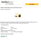
AB-500
Tx Batt
Rew<< Play> FF>>
Learn
Stop
Pause
1 2
3
4
5
6
7
8 9
0
Power
-/--
Ch
Vol
Learn
Error
All Off
OffSelect
Tuner
CD Sat
VCR
DVD TV
TM
Channel Vision
AB-500 ... Universal remote control.. Learns IR
codes for up to 6 sources.
A0127 ... Keypad controller for use with the A4601.
Features:
Available in both white (A0127W) and ivory/almond (A0127IA) colors.
Teaching capability allows controls to be stored in learning remote controls.
User changeable source buttons make it easy to customize.
Source selection buttons
allow any of the 4 sources
to be selected for playback.
Power button.
Turns off the audio and
video playing in a zone.
Mute button.
Mutes the audio playing
in a zone (video will still
be present).
IR receiver.
Detects IR signals and repeats
through the IR system.
Volume +/- buttons.
Increases or decreases
the audio level in a zone.
Changing buttons face plates on the A0127 keypad...
The A0127IA comes with both Almond and Ivory face plates and buttons.
Both the A0127W and A0127IA come with replacement buttons labeled for a
variety of sources.
The procedure below describes the
how to exchange your buttons and
faceplate.
Faceplate tabs
Tuner
Sat
CD
DVD
Zone
CD 2
XM
Sirius
Cam 1
Cam 2
Cam 3
Cam 4
TV
Pwr
Mute
Vid 1
Vid 2
Vid 3
Vid 4
Vol
+
Vol
-
1 Detach the existing faceplate by
pressing the plastic tabs with a flat
blade screwdriver. (Press inward and
upward at a 30 degree angle)
1
2 Exchange the labeled buttons
(and colored faceplate) to your
preference and assemble as
shown
1
30
°
Buttons
Align rubber tabs
with
holes in PCB

Pwr
Mute
Vid 1
Vid 2
Vid 3
Vid 4
Vol
+
Vol
-
Pwr
Mute
Vid 1
Vid 2
Vid 3
Vid 4
Vol
+
Vol
-
2
A0127 Keypad
How IR repeating works
AB-500
Tx
Batt
Rew<<
Play>
FF>>
Learn
Stop
Pause
1
2
3
4
5
6
7
8
9
0
Power
-/--
Ch
V
ol
Learn
Error
All Off
Off
Select
T
uner
CD
Sat
VCR
DVD
TV
TM
Channel V
ision
Point any
IR remote control
at the A0127
CD player
And the flasher
repeats the IR signal
in the other room.
The Pwr button
flashes as IR
information is
received.
Be sure the flasher is attached
directly over the component’s IR
receiver.
3
Accessories
IR-3003 & IR-3002 ... Single and dual head IR
flashers. Use one head per source to control
from the remote room. (IR-3002 shown).
AB-500
Tx Batt
Rew<< Play> FF>>
Learn
Stop
Pause
1 2
3
4
5
6
7
8 9
0
Power
-/--
Ch
Vol
Learn
Error
All Off
OffSelect
Tuner
CD Sat
VCR
DVD TV
TM
Channel Vision
AB-500 ... Universal remote control.. Learns IR
codes for up to 6 sources.
A0127 ... Keypad controller for use with the A4601.
Features:
Available in both white (A0127W) and ivory/almond (A0127IA) colors.
Teaching capability allows controls to be stored in learning remote controls.
User changeable source buttons make it easy to customize.
Source selection buttons
allow any of the 4 sources
to be selected for playback.
Power button.
Turns off the audio and
video playing in a zone.
Mute button.
Mutes the audio playing
in a zone (video will still
be present).
IR receiver.
Detects IR signals and repeats
through the IR system.
Volume +/- buttons.
Increases or decreases
the audio level in a zone.
Changing buttons face plates on the A0127 keypad...
The A0127IA comes with both Almond and Ivory face plates and buttons.
Both the A0127W and A0127IA come with replacement buttons labeled for a
variety of sources.
The procedure below describes the
how to exchange your buttons and
faceplate.
Faceplate tabs
Tuner
Sat
CD
DVD
Zone
CD 2
XM
Sirius
Cam 1
Cam 2
Cam 3
Cam 4
TV
Pwr
Mute
Vid 1
Vid 2
Vid 3
Vid 4
Vol
+
Vol
-
1 Detach the existing faceplate by
pressing the plastic tabs with a flat
blade screwdriver. (Press inward and
upward at a 30 degree angle)
1
2 Exchange the labeled buttons
(and colored faceplate) to your
preference and assemble as
shown
1
30
°
Buttons
Align rubber tabs
with
holes in PCB

4
5
Note: If you are using a Philips Pronto remote control, you may
download IR codes for the A0127 from www.channelvision.com
or from www.remotecentral.com.
INPUTSOUTPUTS
FOR HOME OR OFFICE USE
Channel Vision A4601
Tested To Comply
With FCC Standards
Power
230 / 115 VAC
50 / 60 Hz
Input Voltage
3
R-Audio-L Video
R-Audio-L Video
4
2
1
IR Emitters
1 2 3 4
Hi-Z
75
R-Audio-L Video R-Audio-L Video R-Audio-L Video
2
13
46
5
OUTPUTS OUTPUTS
Control
5
6
Control
3
4
Control
1
2
Sig
Gnd
+V
Video In
Termination
1A/250V
FUSE
115
L IN
LOCAL
GLOBAL
L OUT
R OUT
R IN
L IN
LOCAL
GLOBAL
L OUT
R OUT
R IN
L IN
Sat radio
DVD player
ŸIR emitter outputs allow IR-3002 flashers to be connected for
remote control of source components.
ŸEach zone is controlled through the A0127 keypad which
connects to the RJ45 jacks on the rear panel.
ŸA learning remote (such as the AB-500) can be programmed
to control your source components and the A0127 (see
page 7 for details). This is an easy way to control all your
components from any room in the house.
A4603 Rear Panel
A1260 Rear Panel
CHANNELS
63 4 5
GLOBAL
INPUT
CD player
Room 6
LOCAL
GLOBAL
L OUT
R OUT
R IN
L IN
21
LOCAL
GLOBAL
L OUT
R OUT
R IN
R IN
L IN
LOCAL
GLOBAL
L OUT
R OUT
R IN
L IN
LOCAL
GLOBAL
L OUT
R OUT
R IN
L IN
See page 6 for
connection details
Pwr
Mute
Vid 1
Vid 2
Vid 3
Vid 4
Vol
+
Vol
-
AB-500
Tx
Batt
Rew<<
Play>
FF>>
Learn
Stop
Pause
1
2
3
4
5
6
7
8
9
0
Power
-/--
Ch
V
ol
Learn
Error
All Off
Off
Select
T
uner
CD
Sat
VCR
DVD
TV
TM
Channel Vision

4
5
Note: If you are using a Philips Pronto remote control, you may
download IR codes for the A0127 from www.channelvision.com
or from www.remotecentral.com.
INPUTSOUTPUTS
FOR HOME OR OFFICE USE
Channel Vision A4601
Tested To Comply
With FCC Standards
Power
230 / 115 VAC
50 / 60 Hz
Input Voltage
3
R-Audio-L Video
R-Audio-L Video
4
2
1
IR Emitters
1 2 3 4
Hi-Z
75
R-Audio-L Video R-Audio-L Video R-Audio-L Video
2
13
46
5
OUTPUTS OUTPUTS
Control
5
6
Control
3
4
Control
1
2
Sig
Gnd
+V
Video In
Termination
1A/250V
FUSE
115
L IN
LOCAL
GLOBAL
L OUT
R OUT
R IN
L IN
LOCAL
GLOBAL
L OUT
R OUT
R IN
L IN
Sat radio
DVD player
ŸIR emitter outputs allow IR-3002 flashers to be connected for
remote control of source components.
ŸEach zone is controlled through the A0127 keypad which
connects to the RJ45 jacks on the rear panel.
ŸA learning remote (such as the AB-500) can be programmed
to control your source components and the A0127 (see
page 7 for details). This is an easy way to control all your
components from any room in the house.
A4603 Rear Panel
A1260 Rear Panel
CHANNELS
63 4 5
GLOBAL
INPUT
CD player
Room 6
LOCAL
GLOBAL
L OUT
R OUT
R IN
L IN
21
LOCAL
GLOBAL
L OUT
R OUT
R IN
R IN
L IN
LOCAL
GLOBAL
L OUT
R OUT
R IN
L IN
LOCAL
GLOBAL
L OUT
R OUT
R IN
L IN
See page 6 for
connection details
Pwr
Mute
Vid 1
Vid 2
Vid 3
Vid 4
Vol
+
Vol
-
AB-500
Tx
Batt
Rew<<
Play>
FF>>
Learn
Stop
Pause
1
2
3
4
5
6
7
8
9
0
Power
-/--
Ch
V
ol
Learn
Error
All Off
Off
Select
T
uner
CD
Sat
VCR
DVD
TV
TM
Channel Vision

6
Wiring the A0127 keypad...
Keypads connect to the A4601 through the RJ45 jacks on the back panel of
the A4601. Connections to the A0127 may be accomplished either by using
the RJ45 jack or the screw terminals provided on the back side of the keypad.
When using the RJ45 jacks, simply wire both ends of the cable according to
the TIA568A standard. When using the screw terminals on the A0127, make
sure to wire the RJ45 plug connecting to the A4601 as shown below.
A0127
A4601
Front
Rear
Pin 8: +VDC
Pin 7: Ground
Pin 4: IR signal
Pwr
Mute
Vid 1
Vid 2
Vid 3
Vid 4
Vol
+
Vol
-
Pin 8: +VDC
Pin 7: Ground
Pin 4: IR signal
N.C.
7
Pin 7: Ground
Pin 8: +VDC
Pin 4: IR signal
Stripping and Connecting CAT5 Wire
Blade
CAT5
1. Place the CAT5 between the blade and the first notch of the J-110 tool.
CAT5 cable should be stripped with a proper stripping tool, such as Channel
Vision’s J-110 tool.
Slight
pressure
Rotate
1 turn only
2. Rotate the tool only once. Multiple
turns could damage the inner wires.
3. Inspect the inner wires for damage.
If any wires are cut start over at step 1.
Check for damage
Green/White - Left channel ground
Green - Left channel
Orange/White - Right channel ground
Blue - Signal
Blue/White - Status
Orange - Right channel
Brown/White - Ground
Brown - 24vDC
TIA-568A RJ-45 Modular Plug
Side view:
Top view:

500-071 revD
Channel Vision Technology will repair or replace any defect in
material or workmanship which occurs during normal use of this
product with new or rebuilt parts, free of charge in the USA, for one
year from the date of original purchase. This is a no hassle warranty
with no mail in warranty card needed. This warranty does not cover
damages in shipment, failures caused by other products not supplied
by Channel Vision Technology, or failures due to accident, misuse,
abuse, or alteration of the equipment. This warranty is extended only
to the original purchaser, and a purchase receipt, invoice, or other
proof of original purchase date will be required before warranty
repairs are provided.
Mail in service can be obtained during the warranty period by calling
(714) 424-6500. A Return Authorization number must be obtained
in advance and can be marked on the outside of the shipping carton.
This warranty gives you specific legal rights and you may have other
rights (which vary from state to state). If a problem with this product
develops during or after the warranty period, please contact Channel
Vision Technology, your dealer or any factory-authorized service
center.
Channel Vision products are not intended for use in medical,
lifesaving, life sustaining or critical environment applications.
Channel Vision customers using or selling Channel Vision products
for use in such applications do so at their own risk and agree to fully
indemnify Channel Vision for any damages resulting from such
improper use or sale.
1
Pwr
Mute
Vid 1
Vid 2
Vid 3
Vid 4
Vol
+
Vol
-
8
Setting the A0127 as the master keypad...
By changing a jumper setting on the A0127 you can make it a master keypad.
This simply means that the master A0127 will be able to power on or power off
the entire system from a single zone.
Master control
jumper position
Normal control
jumper position
Power button will
now turn off/on all
zones
When the system
is powered back on
each zone will return
to its previous volume
level and source
selection.
Using the A0505 remote control..
(Download IR codes at: www.channelvision.com and www.remotecentral.com)
designed to control your A4603.
Pwr
Mute
Vid 1
Vid 2
Vid 3
Vid 4
Vol
+
Vol
-
Zone Power - Turns on/off the zone you are in
Power - Master power
(turns all zones on/off)
Mute - Mutes the audio
for the zone you are in
VOL - Controls volume
for the zone you are in
Source Buttons
CH ANN E L V IS I O N
S
O
U
R
C
E
ZONE
POWER
MUTE
4
3
2
1
CAMERA
CATV
MOD
VOL
1
2
3
4
MODEL
A0505
POWER
C
HAN
N
EL V I
S
I
O
N
S
O
U
R
C
E
ZONE
POWER
MUTE
4
3
2
1
CAMERA
CA
TV
MOD
VOL
1
2
3
4
MODEL
A0505
POWER

500-071 revD
Channel Vision Technology will repair or replace any defect in
material or workmanship which occurs during normal use of this
product with new or rebuilt parts, free of charge in the USA, for one
year from the date of original purchase. This is a no hassle warranty
with no mail in warranty card needed. This warranty does not cover
damages in shipment, failures caused by other products not supplied
by Channel Vision Technology, or failures due to accident, misuse,
abuse, or alteration of the equipment. This warranty is extended only
to the original purchaser, and a purchase receipt, invoice, or other
proof of original purchase date will be required before warranty
repairs are provided.
Mail in service can be obtained during the warranty period by calling
(714) 424-6500. A Return Authorization number must be obtained
in advance and can be marked on the outside of the shipping carton.
This warranty gives you specific legal rights and you may have other
rights (which vary from state to state). If a problem with this product
develops during or after the warranty period, please contact Channel
Vision Technology, your dealer or any factory-authorized service
center.
Channel Vision products are not intended for use in medical,
lifesaving, life sustaining or critical environment applications.
Channel Vision customers using or selling Channel Vision products
for use in such applications do so at their own risk and agree to fully
indemnify Channel Vision for any damages resulting from such
improper use or sale.
1
Pwr
Mute
Vid 1
Vid 2
Vid 3
Vid 4
Vol
+
Vol
-
8
Setting the A0127 as the master keypad...
By changing a jumper setting on the A0127 you can make it a master keypad.
This simply means that the master A0127 will be able to power on or power off
the entire system from a single zone.
Master control
jumper position
Normal control
jumper position
Power button will
now turn off/on all
zones
When the system
is powered back on
each zone will return
to its previous volume
level and source
selection.
Using the A0505 remote control..
(Download IR codes at: www.channelvision.com and www.remotecentral.com)
designed to control your A4603.
Pwr
Mute
Vid 1
Vid 2
Vid 3
Vid 4
Vol
+
Vol
-
Zone Power - Turns on/off the zone you are in
Power - Master power
(turns all zones on/off)
Mute - Mutes the audio
for the zone you are in
VOL - Controls volume
for the zone you are in
Source Buttons
CH ANN E L V IS I O N
S
O
U
R
C
E
ZONE
POWER
MUTE
4
3
2
1
CAMERA
CATV
MOD
VOL
1
2
3
4
MODEL
A0505
POWER
CH
AN
NEL
VI
SI
O
N
S
O
U
R
C
E
ZONE
POWER
MUTE
4
3
2
1
CAMERA
CA
TV
MOD
VOL
1
2
3
4
MODEL
A0505
POWER
/