Page is loading ...


"Notice"
Please ensure that this instruction manual is given to the final user of the instrument.
Preface
This instruction manual is meant for those who will be involved in the wiring, installation, operation and routine maintenance of the CN140
series.
This manual describes the care, installation, wiring, function, and proper procedures for the operation of the CN140 series. Keep this
manual at the work site during operation of the CN140 series. While using this instrument, you should always follow the guidance provided herein.
For matters regarding safety, potential damage to equipment and/or facilities, additional instructions are indicated by the following headings:
WARNING
Exercise extreme caution as indicated. This heading indicates hazardous conditions that could cause injury or death of personnel.
CAUTION
Exercise extreme caution as indicated. This heading indicates hazardous conditions that could cause damage to equipment and/or facilities.
NOTE
This heading indicates additional instructions and/or notes.
The mark designates a protective conductor terminal. Make sure to properly ground it.
CN140 Series
Digital controller
Instruction Manual
Thank you for purchasing the Omega CN140 Series. Please check that the delivered product is the correct item you
ordered. Please do not begin operating this product until you have read this instruction manual thoroughly and
understand its contents.

- 2 -
For matters regarding safety
series controller is designed for controlling temperature, humidity
and other physical subjects. It must not be used in any way that may
adversely affect the safety, health or working conditions of those who
come into contact with the effects of its usage. When used, adequate and
effective safety countermeasures must be provided at all times. No
warranty, express or implied, is valid in the case of using this product
without the use of proper safety countermeasures correspondingly.
WARNING
To avoid damage to the connected equipment, facilities or the product
itself due to a fault of the product, safety countermeasure must be taken
before usage, such as proper installation of the fuse and the overheating
protection device. No warranty, express or implied, is valid in the case of
usage without having implemented proper safety countermeasures.
CAUTION
• The mark on the plate affixed to the instrument:
On the terminal nameplate affixed to the case of your instrument, the
mark is printed. This is to warn you of the risk of electrical shock
which may result if the charger is touched while it is energized.
• A means to allow the power to be turned off, such as a switch or a
breaker, should be installed in the external power circuit to be connected
to the power terminal of the instrument.
Fix the switch or the breaker adjacently to the instrument in a position
which allows it to be operated with ease, and with an indication that it is
a means of turning the power off. The switch or the breaker should meet
the requirements of IEC947.
• Fuse:
Since the instrument does not have a built-in fuse, do not forget to install
a fuse in the power circuit to be connected to the power terminal.
The fuse should be positioned between the switch or the breaker and the
instrument and be attached to the L side of the power terminal.
Fuse Rating: 250V AC 0.5A/medium lagged or lagged type
Use a fuse which meets the requirements of IEC127.
• Voltage/current of a load to be connected to the output
terminal and the alarm terminal should be within a rated range.
Otherwise, the temperature will rise and reduce the life of the product
and/or result in problems with the product.
For the rated voltage/current, see 7. Specifications on page 23.
The output terminal should be connected with a device which meets the
requirements of IEC1010.
• A voltage/current different from that of the input specification should
not be added on the input terminal. It may reduce the life of the product
and/or result in problems with the product.
For the rated voltage/current, see 7. Specification on page 23.
For the rated voltage (mV or V) or current (4-20mA) input, the input
terminal should be connected with a device which meets the
requirements of IEC1010 as input terminals.
• As the CT input terminal for the heater break alarm (optional), only the
attachment CT should be used. Using anything else may result in
problems with the product.
For the CT provided, refer to 1-1. Check before Use on page 11.
• The series controller is provided with a draft hole for heat
discharge. Take care to prevent metal or other foreign matter from
obstructing it. Failure to do so may result in problems with the product
and may even result in fire.
• Do not block the draft hole or allow dust or the like to adhere to it. Any
rise in temperature or insulation failure may result in a shortening of the
life of product and/or problems with the product. For spaces between
installed instruments, refer to 2-4. External Dimensions and Panel
Cutout on page 12.
• It should be noted that repeated tolerance tests against voltage, noise,
surge, etc., may lead to deterioration of the instrument.
• Remodeling the instrument or using it in an anomalous way is
prohibited.
CAUTION
Page
1. Introduction...................................................................................3
1-1. Check before use.....................................................................3
1-2. Caution for use........................................................................3
2. Installation and wiring.................................................................3
2-1. Installation site (environmental conditions) ...........................3
2-2. Mounting.................................................................................4
2-3. How to remove the instrument out of the case .......................4
2-4. External dimensions and panel cutout....................................4
2-5. Wiring.....................................................................................5
2-6. Terminal arrangement.............................................................5
2-7. Terminal arrangement table....................................................5
3. Instruction for front panel ...........................................................6
3-1. Drawing and the name of the parts.........................................6
3-2. Instruction for front panel.......................................................6
4. Screen instruction........................................................................7
4-1. Power on and initial screen display ........................................7
4-2. Screen change.........................................................................7
4-3. Screen configuration...............................................................8
4-4. Instruction for screen change and each screen........................9
4-5. Measuring range code table..................................................10
4-6. Alarm type code table...........................................................10
5. Operation....................................................................................10
5-1. Setting of set value (SV).......................................................10
5-2. AT (Auto tuning)..................................................................11
5-3. Setting of alarm.....................................................................12
6. Supplement................................................................................13
6-1. Auto return function..............................................................13
6-2. PID (Screen No.2,4 and 5 of mode 1 screen group).............13
6-3. Control output characteristics...............................................14
(
digit of mode 2 screen)
6-4. Error message .......................................................................14
7. Specifications.............................................................................15
Contents

- 3 -
1. Introduction
1-1. Check before use
This product has been fully checked for quality assurance prior to shipment. Nevertheless, you are requested to make sure that there is no error, damage or
shortage of delivered items by confirming the model codes and checking the external view of the product and the number of accessories.
1-2. Caution for use
(1) Avoid operating keys of the front panel with hard or sharp objects or motions. Lightly touch the operationg keys with finger tip
for operation.
(2) Avoid using solvents such as thinner. Wipe gently with a dry cloth.
2. Installation and wiring
2-1. Installation site (environmental conditions)
In the case where there is an intention to operate this product at one of the following sites, be aware that the occurance of fire and/
or other dangerous situations is considerable.
Exercise caution and avoid these places when selecting an operational site.
CAUTION
(1) Where flammable gas, corrosive gas, oil mist and particles that can deteriorate electrical insulation are generated or are abundant.
(2) Where the temperature is below -10˚C or above 50˚C
(3) Where the relative humidity is 90%RH or below dew point.
(4) Where highly intense vibration or impact is generated or transferred.
(5) Near high voltage power lines or where inductive interference can affect the operation of the product.
(6) Dew drops or direct exposure to sun light.
(7) Where the elevation is in excess of 2,000m.
NOTE: The environmental conditions belong to the installation category II of IEC 664 and the degree of pollution is 2.
- 3 -

2-2. Mounting
(1) Machine the mounting hole by referring to panel cutout in section 2-4.
(2) Applicable thickness of the mounting panel is from 1.0 to 3.5mm.
(3) As this product provides mounting fixture, insert the product from the front panel for installation.
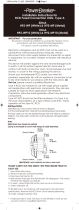
2-3. How to remove the instrument out of the case
- 4 -
When the instrument is removed/replaced in the case, make sure the power is off. If it is done while the power is on, it may lead to
problems with the product and/or other problems.
CAUTION
There is no need to remove your controller out of
the case. Nevertheless, should the need arise, for example,
for replacement, follow the steps described below:
Insert a minius screwdriver of 6mm
~9mm into the opening
(where packing is exposed) of the front case and rotate the
screwdriver while pushing up the lock lever behind the
packing. Once the instrument comes out by a few
millimeters, you can remove it by hand.
2-4. External dimensions and panel cutout
CN146 External dimensions (unit: mm)
CN147 External dimensions (unit: mm)
CN144 External dimensions (unit: mm)
CN148 External dimensions (unit: mm)
Dimension of current transformer (CT) for heater break alarm
30A (CTL-6-S) (unit: mm)
CN146 Panel cutout (unit: mm)
CN147 Panel cutout (unit: mm)
CN144 Panel cutout (unit: mm)
CN148 Panel cutout (unit: mm)
50A (CTL-12-S36-8) (unit: mm)
48
44.7
110
100
10
longer than 60
longer than
60
longer than
100
45
72
67.6
110
100
10
96
91.6
110
100
10
longer than 100
68
92
+
0.8
0
96
48
91.6
44.6
110
100
10
45
+
0.6
0
92
+
0.8
0
+
1
0
92
+
0.8
0
(48 × N-3)
ø 5.8
25
3
10.5
21
30
40
10
2— ø 3.5
40
ø 2.36
ø 12
2-M3 depth4
30
40
15
7.5
longer than
130
longer than 130
longer than 130
When N pieces are installed laterally
N=number
45
+
0.6
0
+
0.6
0
68
+
0.7
0
+
0.7
0
92
+
0.8
0
ENT
PV
SV
˚C
•••
•• •• •••••
••••••••••••••••••••

- 5 -
(1) Wiring operation should be done according to the instruction for the terminal arrangement in section 2-6. Exercise care that no wrong
connection is made.
(2) Crimp terminal should accommodate the M3.5 screw and should have a width of less than 7mm.
(3) For thermocouple input, select the compensation wire suitable to the thermocouple type.
(4) For R.T.D.input, leads should be less than 5 Ω in resistance and three leads should have the same resistance.
(5) Input signal line should be conducted safety apart from the high voltage power line.
(6) Shield wiring (single point grounding) is effective for static induction noise.
(7) Short interval twisted pair wire for input signal is effective for electromagnetic induction noise.
(8) When wiring, use wire (1mm
2
minimum in sectional area) of 600V Grade Polyvinyl Chloride insulated Wire or equivalent wire which has
the same ratings.
(9) Earth grounding should be performed with earth resistance less than 100 Ω and with wire thicker than 2mm
2
.
(10) Noise filter
In case where the instruments are affected by the power supply noise, use a noise filter for preventing malfunction.
Noise filter should be mounted on the grounded panel, the shorted wire should be used to connect between the noise filter output and the
power line terminal.
2-6. Terminal arrangement
CN146
CN144
CN147
CN148
2-7. Terminal arrangement table
NOTE: For CN146, input terminal of heater break and set value bias is common. Start operation after checking the additional function.
For Thermocouple, Voltage, and Current input, measurement error results by connection between B and B terminal.
Recommendable noise filter: TDK ZMB2203-13
Name of terminal and description
Power terminal 100-240V AC±10% 50/60Hz 11VA
Protective conductor terminal ( )
Input terminal R.T.D.A,Thermocouple,Voltage, Current+
Input terminal R.T.D.B,Thermocouple,Voltage, Current–
R.T.D.B
Output terminal Contact COM,SSR Drive voltage,Voltage, Current+
Contact NO, SSR Drive voltage,Voltage, Current–
Contact NC
Alarm output (option) terminal
COM Contact rating 240V AC 1.5A (resistive load)
AH Higher limit alarm
AL/HB Lower limit alarm or heater break alarm
Heater break alarm (option) CT input terminal
Set value bias (option) input terminal
Terminal number
CN146
11 - 12
1
2
3
5
6
7
8
9
10
13 - 14
13 - 14
CN147
8 - 9
10
4
5
7
11
12
13
17
18
19
15 - 16
1 - 2
CN144-148
11 - 12
13
7
8
10
14
15
16
18
19
20
5 - 6
3 - 4
Grounding Grounding
100-
~
240V AC
Noise filter
IN OUT
Controller
100-240V AC
50 / 60Hz
~
The shorted wire should be used here.
IN PUT
RTD
TC • mV
V • mA
+A
-B
B
Power
16
7
8
9
10
2
3
4
5
1
2
3
4
5
6
7
1
2
3
4
5
6
7
8
9
10
11
12
13
14
15
16
17
18
19
20
15
16
17
18
19
20
21
8
9
10
11
12
13
14
NL
C OM+
NO -
C OM
AH
AL/HB
CONTROL
OUTPUT
C OM+
NO -
NC
CONTROL
OUTPUT
ALARM
OUTPUT
CT
or
SB
11 12
13 14
L
N
~
Power
~
SB CT
COM
AH
AL/
HB
IN PUT
RTD
TC • mV
V • mA
+A
-B
B
C OM+
NO -
NC
CONTROL
OUTPUT
L
N
Power
~
C OM
AH
AL/HB
ALARM
OUTPUT
SB
CT
IN PUT
RTD
TC • mV
V • mA
+A
-B
B
1
2
3
4
5
6
7
8
9
10
11
12
13
14
15
16
17
18
19
20
C OM+
NO -
NC
CONTROL
OUTPUT
L
N
Power
~
C OM
AH
AL/HB
ALARM
OUTPUT
SB
CT
IN PUT
RTD
TC • mV
V • mA
+A
-B
B
2-5. Wiring
• Always disconnect this product from any power source during wiring operation to prevent electrical shock.
• Be certain that the protective conductor terminal ( ) is properly grounded. Otherwise, a serious electric shock may result.
• Avoid touching the wired terminal and charged devices while supplying power.
WARNING

- 6 -
Name of parts
: Measured value (PV) display
: Set value (SV) display
: Monitor LED
: Key switches
ENT
PV
SV
˚C
OUT
AT
AH
AL/HB
1
2
3
4
3. Instruction for front panel
3-1. Drawing and the name of the parts
This is an example of the front panel of CN146.
3-2. Instruction for front panel
: Measured value (PV) display (green)
(1) Displays current measured value on the mode 0 basic screen.
(2) Displays parameter type on each parameter screen.
: Set value (SV) display (orange)
(1) Displays set value on the mode 0 basic screen.
(2) Displays selected item and set value on each parameter screen.
: Monitor LED
(1) OUT (output) monitor LED (green)
• For contact or SSR drive voltage output, a light turns on for output ON and turns off for output OFF.
• For current or voltage output, the light intensity changes proportionally to the output altitude.
(2) AT (auto tuning) monitor LED (green)
On selection by , , turns on AT waiting ( key), flashes on AT execution.
(3) AH alarm output monitor LED (red)
Turns on for higher limit alarm output ON.
(4) AL/HB alarm output monitor LED (red)
Turns on for lower alarm output ON or heater break alarm ON.
: Key switches
(1) (parameter) key
• Press on set screen of mode 0 screen group and mode 1 screen group to move to next set screen.
• Keep pressing three (3) seconds for function of move key between basic screen of the mode 0 screen group and direct call screen of
mode 1 screen group.
(2) (down) key
• Press on the set screen to flash the point of the least digit and to reduce data or back increment data.
(3) (up) key
• Press on the set screen to flash the point of the least digit and to increase data or increment data.
(4) (entry/registration) key
• Press on the set screen of the mode 0 screen group and mode 1 screen group to fix the data changed by the keys and to
exthinguish flash of the point.
• Press on the mode 2 screen to fix the data of the point flashing digit and simultaneously to move the data changing digit (point
flashing digit).
• Press for five (5) seconds for function of move key between the basic screen of mode 0 screen group and the mode 2 screen.

- 7 -
4. Screen instruction
4-1. Power on and initial screen display
After turning on power, the display shows each power on initial screen for approx. 1.5 seconds, then moves into the basic screen of the mode 0 screen
group.
4-2. Screen change
(1) Screen change from mode 0 group to mode 1 group
• Keep pressing the key for three (3) seconds on basic screen of the mode 0 screen group to change screen into direct call screen of
mode 1 screen group. Keep pressing the key for three (3) seconds on direct call screen of mode 1 screen group to change
screen into basic screen of the mode 0 screen group.
NOTE: In the above, the mark indicates that the key above the mark is presed. The same applies hereinafter.
(2) Screen change from mode 0 group to mode 2 screen
• Keep pressing key for five (5) seconds on basic screen of the mode 0 screen group to change the screen into mode 2 screen. Keep
pressing key for five (5) seconds on the mode 2 screen to change screen into basic screen of the mode 0 scrren group.
(3) Screen change within mode 0 screen group
• By pressing the key, the screen changes.
• Without alarm option and with ON-OFF action, only basic screen is displayed and no screen change is performed by pressing the
key.
Series type
Input type ( : Thermocouple, : R. T. D., : Voltage(mV),
: Voltage(V), : Contact(mA))
Displays output screen
Output type ( : Contact, : SSR drive voltage, : Current, : Voltage)
Lower limit of the selected measuring range
Higher limit of the selected measuring range
Mode0 screen group basic screen
Measured value (PV)
Set value (SV)
Power on
initial
screen
Turning on power
0-0 basic screen 1-0 direct call screen
key
3 seconds
0-0 basic screen 2-0 Function selecting screen
5 seconds
key
0-0 basic screen 0-1 AT action control screen
0-2 higher limit alarm set screen
key key

- 8 -
(4) Screen change within mode 1 screen group
• Two methods are used for screen change within mode 1 screen group.
• One is to press the key as shown on above mode 0 screen group.
• The other is to mode the screen directly by indicating screen No. on the top direct call screen.
Example: Direct calling the screen No.8 PV bias value set screen
(5) Selecting and setting digit to change of mode 2 screen
• When mode 2 screen is displayed, the point of selectable digit flashes.
• By pressing key, the selectable digit (digit whose point is flashing) moves.
• In case of changing the set value, flash the point to be changed with key,
select data with the keys and press key again to register the set value and move selectable digit.
Example: changing the control output characteristics from (heating) to (cooling)
* "." on the screen shows the selectable digit (digit whose point is flashing).
(6) Shifting setting items on input scaling screen of mode 2 screen group and setting method
• Pressing the key on the function selecting screen calls the input scaling screen onto the display. The decimal point in the rightmost position on
the top row flashes.
Press the or key to change the lower limit value and press the key to register the data.
• Upon registering the lower limit value data, the decimal point in the rightmost digit in the botton row begins to flash. Change the higher limit
value by pressing the or key and register it by means of the key.
• Upon registering the higher limit value data, the decimal points in the rightmost digits of the bottom and top rows flash. Change the positions of
the decimal points by pressing the or key and register it by means of the key.
• Each time the key is pressed, the flashing decimal point in the rightmost digit moves from the top row → bottom row → top and bottom rows
→ top row →.
• In case the lower limit value and the higher limit value are set to produce a difference which is less than 10 counts or more than 5000 counts, the
higher limit value is forced to change to +10 or +5000 counts. The higher limit cannot be set to be less than a lower limit value +10 counts or
more than a lower limit value +5000 counts.
NOTE: In case of changing data and pressing key longer than 5 seconds, the screen moves to mode 0 basic screen without a data
registration. It requires a data verification with key and screen change.
4-3. Screeen configuration
In the CN140 series controller, the screen configuration is divided into screen groups and screens corresponding to the frequency of usage in their
operation.
(1) Mode 0 screen group
It is made up of screens of relatively high frequency in use for operation, i.e., the basic screen (for setting target value and confirming current
measured value), the auto tuning action control screen and the alarm setting screens.
(2) Mode 1 screen group
Made up of screens of less frequency than those of mode 0 group, i.e., screens for setting values to be changed as required by input conditions or
control capability and a screen for locking items not to be changed.
(3) Mode 2 screen (function slecting screen)
Once items are set in this screen, the need to change them seldom arises; selected code of measuring range, selected output characteristic, slected type
of optional alarm functions, and selected action mode of heater break alarm are displayed on this single screen.
(4) Method of changing data
Press the or key to change data in each screen and press the key to register the changed data.
1-0 direct call screen 1-0 direct call screen 1-8 PV bias value set screen
keykey
several times point flashes
key key key

0-0
for ON/OFF
for
ON/OFF
No option
0-1
0-2
0-3
1-0
2-0
1-1
1-2
I ≠ OFF
I=OFF
1-3
1-4
2-1
1-5
1-6
1-7
1-8
1-9
1-10
=
=
keep pressing key for five (5) seconds
keep pressing
for three (3) seconds
key
Mode 1 screen group
Mode 2 screen group
Function selecting screen
1
2
3
4
5
6 7 8
- 9 -
4-4. Instruction for screen change and each screen
Mode 0 screen group
Basic screen
SV initial value: lower limit of
mesuring range
Setting range: within measuring
range
Upper row displays measured
value (PV) and lower row displays
and changes the set value (SV).
Refer to 5-1 for detail.
AT (auto tuning)
action control screen
Initial value: OFF
Setting range: OFF,ON
For "ON" selection, AT is executed
and for "OFF" selection, AT is
cancelled.
Refer to 5-2 for detail.
Higher limit alarm set screen
Initial value:
absolute value alarm higher
limit for the measuring range
Deviation alarm 2000 unit
Setting range:
absolute value alarm within
measuring range
Deviation alarm 0~2000 unit
Displays except the case with
alarm option and the alarm type of
the mode 2 screen is not specified.
Refer to 5-3 (1) for detail.
Lower limit alarm set screen
Initial value:
absolute value alarm lower
limit for the measuring range
Deviation alarm -1999unit
Setting range:
absolute value alarm within
measuring range
Deviation alarm -1999~0 unit
Displays in case with alarm option
and the alarm type of the mode 2
screen is higher limit and lower
limit.
Refer to 5-3 (2) for detail.
Heater break alarm value set screen
Initial value: OFF
Setting range: OFF, 0.1~50.0A
Displays in the case with heater
break alarm option and alarm type
of the mode 2 screen is higher limit
+ heater break.
Refer to 5-3 (3) for detail.
Use key to move select digit and data
registration, the selectable digit is
indicated by flashing point.
Upper row displays load current detected by CT.
(If the output is OFF, it shows )
NOTE: The heater break alarm can be added if the
instrument has alarm option and the control
output is the contact type or the SSR drive voltage
type.
Heater break alarm
• Set the alarm level at approx. 85% of the normal load current.
In case of large current variation, set larger value.
If multiple heaters are connected in parallel, set a larger value
to output alarm for single heater break.
• If "OFF" is selected, no alarm output is obtained.
Selecting "OFF" during alarm output, the alarm output is
canceled.
• For case when heater break function is not applicable to direct
current load, phase controlling current and three phase heater.
• Connecting current transformer (CT)
One of the load line wires passes through the hole of the
custom CT.
Wire from the secondary side terminal of CT to the CT input
terminal of the instrument.
NOTE: Two types of the heater break CT of 30A and 50A are
available, the type selected upon ordering is shipped
with the product as an accessory. Note the maximum
current to be set is 50.0A for both types.
NOTE: If it is on auto tuning excution or key lock is set
on lock No.1,2 or 3, no selection can be
performed even if the digit point is flashing.
Digit and are not shown in case of no option Digits of ,
and are not displayed.
•: Measuring range code select digit
Initial value: Multi05, voltage V81, Current 95 fixed.
Selecting two digits from "4-5. Measuring range code
table"
: Control output characteristic select digit
Initial value: : Refer to 6-3.
: RA (heating characteristics)
: DA (cooling characteristics)
: Alarm type select digit
Initial value:
Select from "4-6. Alarm type code table"
: Heater break alarm action mode select digit
Initial value:
Select from
: Lock mode and : REAL mode.
Refer to 5-3 (3).
Input scaling screen
Initial value:
Lower limit value (top row) 0.0
Higher limit value (bottom row) 100.0
Position of decimal point 0.0
Setting range:
Lower limit value -1999~9989 units
Higher limit value -1989~9999 units
Span = Higher limit value - Lower limit
value
= 10~5000 counts
Position of decimal point:
No decimal point, 0.0, 0.00 and 0.000
Scaling is done for linear input (mV, V or mA).
The screen is only for monitoring and no setting is possible in
the case of sensor input.
Refer to Item 4-2 (6) for details.
NOTE: Screen flame on 4-4 is as follows:
Screens always shown during key
operation.
Screens shown during case with
option or selected option.
Screens shown or skipped depending
on control action mode.
(PID action or ON/OFF action)
Lock No.
OFF
1
2
3
Screen range locked
Unlock (all data change enabled)
Basic screen, Key lock for screens except AT action control screen
Key lock for screens except basic screen.
All key lock
To CT input terminal of
controller (no polarity)
Heater (load) wire
Direct call screen (screen No.0)
Initial value: 0
Setting range: 0~12
Set the screen No. to move the screen of the mode
screen group.
Refer to 4-2 (4) for detail.
The screen with no display condition is skipped.
Set value blas set screen (screen No.1)
Initial value: 0
Setting range: -1999~2000 unit
Displays in the case with set value bias option. The set
value is effective during shorted SB terminal, and is
added to or subtracted from the set value. The point of
the least digit of the lower row turns on while this
function is effective.
Proportional band set screen (screen No.2)
Initial value: 3.0%
Setting range: OFF, 0.1~999.9%
Not required in case of auto tuning. Refer to 6-2 (1)
for proportional band. Select "OFF" to perform
ON/OFF (two position) action.
Action hysteresis set screen (screen No.3)
Initial value: 3 or 0.3
Setting range: 1~999 unit
Set ON/OFF hysteresis on ON/OFF action.
Not displayed on PID action.
Integral time set screen (screen No.4)
Initial value: 120 seconds
Setting range: OFF, 1~6000 seconds
Not required for auto tuning.
Refer to 6-2 (2) for integral time.
Not shown on ON/OFF action.
Derivative time set screen (screen No.5)
Initial value: 30 seconds
Setting range: OFF, 1~3600 seconds
Refer to 6-2 (3) for derivative time.
Not shown on ON/OFF action.
Manual reset value setting screen (screen No.6)
Initial value: 0.0%
Setting range: -50.0~+50.0%
Offset is adjusted when I=OFF (P or PD action) is
selected.
This screen appears only when I=OFF has selected.
Manual Reset Value
In the PID operation, an offset is corrected
automatically by I,i.e, integral calculation. When it is
set at OFF, this correction is not made and output is
manually increased or decreased for correction. This
is called manual reset (MR).
Set value function set screen (screen No.7)
Initial value: 0.40
Setting range: OFF, 0.01~1.00
Used for suppressing overshooting and undershooting in
expert PID. For SF=1.00 minimize overshooting, for
SF=OFF, expert PID is unable to be normal PID action.
Not shown on ON/OFF action.
PV bias value set screen (screen No.8)
Initial value: 0 or 0.0
Setting range: -200~200 unit
Used for sensor input error compensation.
Controlling is performed with corrected value for bias
setting.
PV filter time set screen (screen No.9)
Initial value: 0 second
Setting range: 0~100 seconds
Used for the case of large input change and noise
overlapping to reduce the effect.
Key lock mode set screen (screen No.10)
Initial value: OFF
Setting range: OFF, 1,2,3
Lock the item not to be changed.
No data change is effective on the display screen locked.
Following table shows the lock No. and screen range
locked.

- 10 -
4-5. Measuring range code table
5. Operation
5-1. Setting of set value (SV)
(1) Set value setting is performed on basic screen of the mode 0 screen group.
(2) Press the or key to set set value. Keep pressing it to flash the point of the least digit of set value and increase (or decrease) value.
(3) After confirming the value to coincide the set value, press to register the data.
(4) After registration of the data, the point of the least digit goes off.
Example: Setting set value to 500˚C
4-6. Alarm type code table
NOTE: The inhibit action on the alarm type code table above is the action which outputs alarm when the measured value enters
alarming range again after inhibiting alarm output for the value within the alarming range and allows it out of the range once.
Input type Code
01
02
03
04
05
06
07
08
09
10
11
31
32
33
34
35
36
37
38
71
72
73
81
82
83
95
Multi input
Thermocouple
R.T.D.
Voltage mV
Voltage V
Current 4
~20mA
*1B
R
S
K
K
E
J
T
N
*2U
*2L
Measuring range (˚C)
0~1800
0~1700
0~1700
–100 ~ 400
0~1200
0~700
0~600
–199.9~ 200.0
0~1300
–199.9~ 200.0
0~600
–200 ~ 600
–100.0~ 100.0
–50.0~ 50.0
0.0~ 200.0
–200 ~ 600
–
100.0~ 100.0
–50.0~ 50.0
0.0~ 200.0
Initial value: 0.0 ~ 100.0
Conditions of scaling
Scaling setting range:
–1999~9999,
Span: 10~5000 counts
Position of decimal point:
No decimal point, the first second
and third decimal places
Code
12
13
14
15
16
17
18
19
20
21
22
39
40
41
42
43
44
45
46
Measuring range (˚F)
0~3300
0~3100
0~3100
–150 ~ 750
0~2200
0~1300
0~1100
–300 ~ 400
0~2300
–300 ~ 400
0~1100
–300 ~1100
–150.0~ 200.0
–
50.0~ 120.0
0~400
–300 ~1100
–
150.0~ 200.0
–50.0~ 120.0
0~400
*1 Thermocouple B: Accuracy not guaranteed
for temperatures below 400˚C (750˚F).
*2 Thermocouple U,L: DIN43710
Thermocouple B,R,S,K,E,J,T,N:
JIS/ANSI/IEC
R.T.D.Pt100: Present JIS/IEC
JPt100: FormerJIS
Alarm code
0 ( )
1 ( )
2 ( )
3 ( )
4 ( )
5 ( )
6 ( )
7 ( )
8 ( )
AH assignment
With/Without inhibit
action
AL/HB assignment
Not assigned
Higher limit deviation
value
Higher limit absolute
value
Higher limit deviation
value
Higher limit absolute
value
Higher limit deviation
value
Higher limit absolute
value
Higher limit deviation
value
Higher limit absolute
value
–
Without inhibit action
Without inhibit action
With inhibit action
With inhibit action
Without inhibit action
Without inhibit action
With inhibit action
With inhibit action
Not assigned
Lower limit deviation
value
Lower limit absolute
value
Lower limit deviation
value
Lower limit absolute
value
Heater break
Heater break
Heater break
Heater break
With/Without inhibit
action
Without inhibit action
Without inhibit action
With inhibit action
With inhibit action
–
–
–
–
–
0-0 basic screen one by one
continuing point flashing point flashing point goes off to
indicate registration
key key key
Pt100
JPt100
0
~10
10
~50
0
~100
0
~1
1
~5
0
~10
NOTE: In case types of Alarms are changed, values are intialized.
NOTE: In case measuring range is modified, set values, alarm action point and other related values are all initialized.

- 11 -
5-2. AT (Auto tuning)
(1) Execution of AT action
• Auto tuning function is prepared for suitable control by using PID control action with constants of P: proportional band, I: integral time and D:
derivative time calculated for PID control which are automatically stored in the internal memory.
• By pressing the or key AT action control screen, display on lower row turns into and the point of the least digit starts flashing,
then the LED for AT monitoring turns on to indicate AT standby. Press key to start AT action with point going off and LED for AT monitoring
flashing.
• During AT execution, PID constants are defined by calculation for ON/OFF action (100%/0%) output for the measuring value increase and decrease
around the set value and store internal memory. Control action according to stored PID constant is started. Then the LED for AT monitoring goes
off and the display on the AT action control screen is changed to .
(2) Abort of AT
To abort the AT action, by showing the AT action control screen, press the or key to select and press key to abort AT and LED for
AT monitoring also goes off.
NOTE: When the AT action is aborted, each value for PID is not changed.
(3) AT unable for following conditions.
• The proportional band is " " setting (ON/OFF action). (No AT screen is shown.)
• Lock No.2 or 3 is selected on the key lock set screen.
• PV (measured) value is over the scale.
(4) AT is automatically canceled in the following condition during AT execution.
• Duration equal to or longer than 2 hours passed in the output level of 0% or 100%.
• Power shutdown.
• PV (measured) value is over the scale during AT execution.
(5) Starting AT (selecting " " on the selection screen) during AT execution, no AT is performed and continues running AT execution.
(6) The items enable to be set are as follows:
• Level setting of the higher limit alarm.
• Level setting of the lower limit alarm or heater break alarm.
• Screen number setting on the direct call screen of mode 1 screen group.
(7) Relationship between AT and set value bias is as follows:
• When SB terminal is shorted before AT execution, AT executes in the condition with SV + set value bias.
• When SB terminal is opened during AT execution mentioned in the above, AT executes with SV + set value bias condition, then controlled with SV
condition after completing AT execution.
• When SB terminal is opened, AT executes with SV condition.
• When SB terminal is shorted during AT execution mentioned in the above, AT executes with SV condition, then controlled with SV + set value bias
condition after completing AT execution.
0-0 basic screen
0-0 AT action
control screen
LED for AT
monitoring
turns on
LED for AT
monitoring
starts flashing
point flashing point goes off to
indicate registration
key
key key
Starting
AT action
0-0 basic screen
LED for AT
monitoring
starts flashing
0-1 AT action control screen
LED for AT
monitoring
flashing
LED for AT
monitoring
turns on
LED for AT
monitoring
goes off
point flashing point goes off to
indicate registration
key
key key
Aborting
AT action

- 12 -
5-3. Setting of alarm
(1) Higher limit alarm setting
• The higher limit alarm set screen is shown in case where alarm option is added and the higher limit alarm of the alarm type select digit on mode 2
screen is selected.
• Higher limit deviation value alarm is output for measured value to be greater than set value + alarm set value.
• For higher limit deviation value alarm, if set value + alarm set value exceeds the higher limit of the measuring range, the action point is the higher
limit of the measuring range.
• Higher limit absolute value alarm outputs alarm signal for the measured value exceeds the alarm set value.
• Higher limit absolute value alarm is set on any value within the measuring range.
• Higher limit alarm set screen is shown by pressing the key on AT action control screen.
• With the or key, value at which the alarm signal should be output is selected and registered with key.
• Operation of the or key is identical with set value setting.
Example 1: In case of setting the alarm action point at 600˚C for higher limit deviation value alarm. Set value is 500˚C.
As 500˚C+X˚C=600˚C, X=600-500=100˚C should be set.
Example 2: In case of setting the alarm action point at 600˚C for higher limit absolute value alarm,
the set point is action point.
(2) Lower limit alarm setting
• The lower limit alarm set screen is shown in case where alarm option is added and the lower limit alarm of the alarm type select digit on mode 2
screen is selected.
• Lower limit deviation value alarm is output for measured value to be less than set value + (alarm set value).
• For lower limit deviation value alarm, if set value + (alarm set value) is less than the lower limit of the measuring range, the action point is lower
limit of the measuring range.
• Lower limit absolute value alarm outputs alarm signal for the measured value is less than the alarm set value.
• Lower limit absolute value alarm is set on any value within the measuring range.
• Lower limit alarm set screen is shown by pressing the key on higher limit alarm set screen.
• With the or key, value at which the alarm signal should be output is selected and registered with key.
• Operation of the or key is identical with higher limit alarm setting.
Example 1: In case of setting the alarm action point at 300˚C for lower limit deviation value alarm,
set value is 500˚C.
As 500˚C+(X˚C)=300˚C, X=300-500=-200˚C should be set.
Example 2: In case of setting the alarm action point at 300˚C for lower limit absolute value alarm,
the set point is action point.
0-2 higher limit deviation value alarm set screen
point flashing point flashing
point goes off to
indicate registration
key key key
one by one
continuing
0-2 higher limit alarm set screen
point flashing point flashing
point goes off to
indicate registration
keykey key
one by one
continuing
0-3 lower limit deviation value alarm set screen
point flashing point flashing
point goes off to
indicate registration
keykey key
one by one
continuing
0-3 lower limit alarm set screen
point flashing point flashing
point goes off to
indicate registration
keykey key
one by one
continuing

- 13 -
(3) Heater break alarm setting
• The heater break alarm set screen is shown in case where heater break alarm option is added and heater break alarm of the alarm type select digit on
mode 2 screen is selected.
• Displayed by pressing the key on higher limit alarm set screen, upper row shows the real time current value and lower row shows alarm action
current set value.
• Break alarm value can be selected from OFF and range of 0.1~50.0A, heater break alarm is disabled by selecting OFF.
• By setting OFF during heater break alarm signal output, heater break alarm output is terminated.
• For set value other than OFF, heater break alarm signal is output if the current that flows in case where control output (contact or SSR drive voltage)
is ON, is less than set value.
• If LOCK mode is selected at heater break alarm action mode select digit on mode 2 screen and the break alarm signal is output, alarm signal is only
terminated by changing the break alarm value into OFF or shutting down power.
If REAL mode is selected and heater current is less than current value being set, break alarm signal is generated. If heater current exceeds the
current threshold (0.1A), output of break alarm is terminated.
• With the or key, value at which heater break alarm signal should be output is set and registered with key.
Example: In case of setting heater break alarm action point at 25.0A.
6. Supplement
6-1. Auto return function
When no key action is made for longer than three (3) minutes on each screen except heater break alarm value set screen, the screen moves back to the
basic screen of the mode 0 screen group (auto return).
6-2. PID (Screen No.2,4 and 5 of mode 1 screen group)
PID values are automatically set by performing auto tuning, modification may be required for object to be controlled.
If auto tuning is not performed, PID values should be set. Description for PID is as follows:
(1) P (proportional action)
Control output rate (%) is set for measuring range.
Control output value changes in proportion with measured value (PV) and set value (SV).
For wide proportional band, change of control output is small relative to deviation. The narrower the proportional band is, the larger the output
variation is and the more intense proportional action is. Too narrow proportional band causes ON-OFF like action with oscillation (hunting). By setting
P to be OFF, ON-OFF action is performed.
(2) I (integral time)
A function that compensates the offset created by proportional action. Effect of compensation is weaker for longer integral time and is intensified by
shortening time. Too short integral time causes integrating hunting and may result in wavy operation.
(3) D (derivative time)
Improves stability of control by reducing overshooting of integration from expected change of the control output. Effect of compensation is weaker for
shorter derivative time and is intensified for longer time. Too long derivative time may result in oscillating operation.
0-4 heater break alarm set screen
point flashing point flashing
point goes off to
indicate registration
keykey key
one by one
continuing

- 14 -
(2) (DA characteristics)
Control output decreases for lower measured value relative to set value, it is used for cooling on temperature control.
6-4. Error message
The following error messages are shown on the PV display screen in case of defect.
(1) Defect of measuring input
In case of thermocouple break, R.T.D.A break and PV being approx. 10% greater than higher limit of measuring range.
In case of PV being approx. 10% less than the lower limit of measuring range with inverted polarity of input wiring.
Cold junction (CJ) defect to higher side for thermocouple input.
Cold junction (CJ) defect to lower side for thermocouple input.
Break of B or B and multiple break of A, B, B upon R.T.D. input
(2) Defect of heater break alarm CT
CT input value is greater than 55A.
CT input value is less than -5A.
NOTE: Message of heater break alarm is only displayed on heater break alarm set screen.
is shown when output is OFF. It is not defective.
NOTE: Contact to us or our representative in case of any defect regarding this product.
100%
0%
low high
low high
PV
P
**
P
SV
100%
0%
PV
SV
P=Proportionl
band
(RA characteristics) (DA characteristics)
Control
output
Control
output
*
6-3. Control output characteristics ( digit of mode 2 screen)
Control output characteristics determines the control output direction according to the measured value (PV) relative to the set value (SV).
(1) (RA characteristics)
Control out put increases for lower measured value relative to set value, it is used for heating on temperature control.

-
15 -
7. Specifications
Display
• Digital display
• Parameter display
• Action display
• Display accuracy
• Display accuracy range
• Display resolution
• Measured display range
• Sampling cycle
Setting
• Setting
• Setting range
Input
• Type of input
• Thermocouple
External resistance
Input impedance
Burnout
Cold junction temperature
compensation accuracy
• R.T.D.
Amperage
Lead wire tolerable resistance
• Voltage
Input impedance
• Current
Receiving impedance
• Input scaling function
Scaling range
Span
Position of decimal point
• Sampling cycle
• PV bias range
• PV filter
• Isolation
Control
• Control mode
• Proportional band (P)
• Integral time (I)
• Derivative time (D)
• Manual reset (MR)
• On-Off hysteresis
• Proportional cycle
• Control output characteristics
• Set value function (SF)
Control output type/rating
• Contact output CN146
CN147, CN144, CN148
• Current output
• SSR drive voltage output
• Voltage output
• Isolation
Alarm Output (option)
• Number of alarm points
• Alarm Type
: Measured value (PV) /7-segment green LED 4 digits
: Set value (SV) /7-segment orange LED 4 digits
: 7-segment LED for PV and SV
: Green LED for two points of output (OUT) and auto tuning (AT)
: Red LED for two points of alarm (AH,AL/HB)
: ±(0.5% FS+1 digit) excluding cold junction temperature compensation accuracy in the case of
the thermocouple input.
±5% FS for temperatures below 400˚C (750˚F) of thermocouple B.
: 23±5˚C (18~28˚C)
: Depends on measuring range (0.1, 1)
:
–10~110% (-210~680˚C for -200~600˚C of R.T.D. input)
: 0.5 sec.
: By 4 front key switches
: Same as measuring range
: Multiple input of Thermocouple, R.T.D.,Voltage (mV), or Voltage (V), or Current 4~20mA DC by code
selection.
: B, R, S, K, E, J, T, N, {U,L (DIN 43710)} Refer to Measuring range code table.
: 100Ω max.
: 500kΩ min.
: Standard feature (up scale)
: ±2˚C (˚F) (5~45˚C)
±5˚C to the negative side of measuring range in case of T and U input, though.
: JIS Pt100/Jpt100 3-wire type
: Approx. 0.25mA
: 5Ω max./wire (The 3 lead wires should have same resistance.)
: 0~10, 10~50, 0~100mV DC or 0~1, 1~5, 0~10V DC
: 500kΩ min.
: 4~20mA DC
: 250Ω
: Scaling possible for voltage (mV, V) or current (mA) input.
:
–1999~9999 counts.
: 10~5000 counts
: None, 0.0, 0.00, 0.000
: 0.5 sec.
: ±20.0 unit in case the decimal point is included in the measuring range. If not, ±200 unit.
: 0~100 sec. (0=without filter)
: Insulated between input and output (not insulated between input and system, SV bias and CT input)
: Auto tuning PID
: Off, 0.1~999.9% FS (Off setting: On-Off action)
: Off, 1~6000 sec. (Off setting: P or PD action)
: Off, 1~3600 sec. (Off setting: P or PI action)
:
–50.0~50.0% (Valid when P≠OFF and I=OFF)
: 1~999 unit
: Fixed to 20 sec. during contact output
Fixed to 2 sec. during SSR drive voltage output
: RA/DA selectable (set to RA when shipeed)
: Off (Off=0.00) and 0.01~1.00
: 240V AC 2.0A/resistive load: 1.2A/inductive load
: 240V AC 2.5A/resistive load: 1.5A/inductive load
: 4~20mA DC/load resistance: 60Ω max.
: 15±3V DC (with load resistance at 1.5kΩ )/load current: 20mA max.
: 0~10V DC/load current: 2mA max.
: Isolation between control output and system and input
: 2 (AH and AL/HB) (for both normal open and common)
: Selectable from combinations of the following 9 types
0. Not assigned
1. Higher limit deviation value + lower limit deviation value without inhibit action
2. Higher limit absolute value + lower limit absolute value without inhibit action
3. Higher limit deviation value + lower limit deviation value with inhibit action
4. Higher limit absolute value + lower limit absolute value with inhibit action
5. Higher limit deviation value without inhibit action + heater break
6. Higher limit absolute value without inhibit action + heater break
7. Higher limit deviation value with inhibit action + heater break
8. Higher limit absolute value with inhibit action + heater break

• Alarm setting range
Deviation value
• Alarm action
• Alarm action hysteresis
• Alarm output/rating
Heater Break Alarm (option)
This function can be added if the instrument has an alarm option and the control output is the contact type or the SSR drive voltage type. In SR71,
addition is possible unless it has an SV bias option.
• Alarm action
• Current setting range
• Setting resolution
• Amperage display
• Display acuuracy
• Minimum time for action confirmation
• Alarm holding
• Sampling cycle
• Isolation
Set value Bias (option)
In CN146, this function can be added unless it has a Heater Break Alarm option.
• Setting range
• Setting resolution
• Action input
• Isolation
Others
• Data storage
• Operating ambient temperature
/humidity range
• Supply voltage
• Power consumption
• Applicable standard Safety
EMC EMI (emission)
EMS (immunity)
• Insulation resistance
• Dielectric strength
• Protective structure
• Material
• External dimensions CN146
CN147
CN144
CN148
• Mounting
• Panel thickness
• Panel cutout CN146
CN144
• Weigh CN146
CN144
- 16 -
: Higher limit and lower limit absolute value alarms: Within full scale of measuring range
: Higher limit: 0~2000 unit
Lower limit:
–1999~0 unit
In case SV is out of the measuring range, higher and lower limit values of the measuring range become the
action points.
: On-Off action
: Fixed to 0.2% of the measuring range
: Contact 1a (common)/240V AV 1.5A (resistive load)
: Heater amperage detected by externally attached CT. Alarm output
On upon detection of heater break while control output is On.
: Off, 0.1~50.0A (Alarm action stops when Off is set.)
: 0.1A
: 0.0~55.0A
: 5% FS (when sine wave is 50Hz)
: On time:500 msec.
: Selectable between Lock (holding) and Real (not holding)
: 2 sec.
: Insulated between CT input and control output (not isolated between CT input and system and other
inputs)
:
–1999~2000 unit
: Same as display resolution
: Non-voltage contact (bias in action when SB terminal is closed)
: Insulated between the SV bias input and the control output (not isolated between the SV bias and the
system and other input)
: By non-volatile memory (EEPROM)
:
–10~50˚C/90% RH max. (no dew condensation)
: 100-240V AC±10% (50/60 Hz)
: Approx. 11VA
: IEC1010-1
: EN50081-1
: EN50082-2
: Between input/output terminal and power supply terminal:
500V DC 20MΩ minimum
Between input/output terminal and protective conductor terminal:
500V DC 20MΩ minimum
: 1 min. at 2300V AC between input/output terminal and power supply terminal
1 min. at 1500V AC between power supply terminal and protective conductor terminal
: Only front panel has simple dust-proof and drip-proof structure
: PPO resin molding (equivalent to UL94V-1)
: H48
×W48×D110 (panel depth:100) mm
: H72
×W72×D110 (panel depth:100) mm
: H96
×W96×D110 (panel depth:100) mm
: H96
×W48×D110 (panel depth:100) mm
: Push-in panel (one-touch mount)
: 1.0~3.5 mm
: H45
×W45 mm, SR72: H68×W68 mm
: H92
×W92 mm, SR74: H92×W45 mm
: Approx.180g, SR72: Approx.260g
: Approx.330g, SR74: Approx.250g


/