Page is loading ...

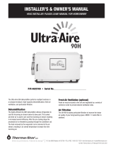
Wire
Routing
Port
Wiring
Access
Filter
A
ccess
H
umidity
Control
I
nlet
Drain
On/Off
Switch
Filter
A
ccess
S
ervice
Access
Port
Outlet
Installation, Safety & Maintenance Manual
Model 1750/1770
Dehumidifier
INSTALLER – PLEASE NOTE!
1. Installation must conform to all applicable codes.
2. For the 1750, a dedicated 15 Amp circuit is recommended but not required for proper operation of the
dehumidifier. If a dedicated circuit is not available, use a lightly loaded circuit. Do not use an extension cord.
3. For the 1770, a dedicated 20 Amp circuit is required for proper operation of the dehumidifier.
If a dedicated circuit is not available, do not install unit. Dehumidifier must be plugged in directly to an outlet.
Do not use an extension cord.
4. For protection of the compressor, unit must be transported and installed in an upright position.
If the unit was shipped or stored on its side, a 24 hour settling period is required before running the unit.
TABLE OF CONTENTS
Safety Instructions . . . . . . . . . . . . . . .2
Overview . . . . . . . . . . . . . . . . . . . . . . .2
Specifications . . . . . . . . . . . . . . . . . . .2
Location Notes . . . . . . . . . . . . . . . . . .2
Ducting . . . . . . . . . . . . . . . . . . . . . . . .3
Drain Line . . . . . . . . . . . . . . . . . . . . . .3
Hanging . . . . . . . . . . . . . . . . . . . . . . .3
Installations
Central . . . . . . . . . . . . . . . . . . . . . . . .4
Localized . . . . . . . . . . . . . . . . . . . . . . .6
Central/Zoned . . . . . . . . . . . . . . . . . . .8
Air Cycling . . . . . . . . . . . . . . . . . . . .10
Float Switch . . . . . . . . . . . . . . . . . .12
Dip Switch Definitions . . . . . . . . . . .12
System Checkout . . . . . . . . . . . . . . .13
Troubleshooting . . . . . . . . . . . . . . . .14
Sequences
of Operations . . . . . . . . . . .Back Cover
90-121590-1214

2
SAFETY INSTRUCTIONS
WARNING
Do not use
solvents/cleaners
on or near the
circuit boards.
CAUTION
OVERVIEW
SPECIFICATIONS
Dimensions: 20
3
⁄4”W x 24”L x 20
3
⁄8”H (mounting feet fully engaged)
20
3
⁄4”W x 24”L x 23
5
⁄8”H (mounting feet fully extended)
Weight: 1750 - 93 lbs. 1770 - 100 lbs
Capacity: 1750 - 90 pints per day @ 60%RH, 80°F
1770 - 150 pints per day @ 60%RH, 80°F
(ANSI/AHAM DH-1-2003 conditions)
Power: 1750 - 115 VAC, 8 Amps. 1770 - 115 VAC, 14 Amps.
Unit is equipped with an 8 ft. grounded power cord.
This Aprilaire Central Dehumidifier is designed specifically to control humidity inside the whole home as well as in crawlspaces
and attics. This dehumidifier automatically and continually measures the true measure of moisture level, dew point. The unit
operates to control humidity to the dryness set point that is either set on the unit or on the optional living space control.
A built-in, automatic air cycling feature can be utilized to activate the HVAC fan to cycle the air throughout the whole home for
proper balance for comfort. See Air Cycling, page 10, for more details on this feature.
This dehumidifier also has a patented, built-in ventilation feature, which will allow fresh air to be brought into the home from the
outside. In utilizing this feature, the dehumidifier will dehumidify the incoming air, if needed (based on dew point / dryness set
point), as the outside air is first entering the home. The built-in ventilation feature is designed to be able to meet ASHRAE 62.2
Standard for Ventilation. See Ventilation, page 10, for more details on this feature.
LOCATION NOTES
Design Airflow: 1750 - 275 CFM @ 0.6 in. w.c.
1770 - 500 CFM @ 0.6 in. w.c.
Filter: MERV 8 Filter
Cabinet Insulation: 1” foil faced EPS insulation
Inlet Air Operating Conditions: 40°F to 105°F
Ambient Air Operating Conditions: 40°F to 150°F
• This product must be installed by a qualified heating and air conditioning contractor.
Failure to do so could result in serious injury from electrical shock or damage to product.
• 120 volts may cause serious injury from electric shock. Disconnect electrical power
before starting installation. Leave power disconnected until installation is completed.
• Sharp edges may cause serious injury from cuts. Use care when cutting plenum
openings and handling ductwork.
• Unit weight and dropping may cause personal injury or equipment damage.
Handle with care.
REQUIREMENT
APPLICATION LOCATION
ATTIC GARAGE BASEMENT CRAWLSPACE
All ductwork must be insulated and sealed
✓ ✓ ✓
Drain pan with overflow protection should be placed under the
unit to prevent water damage in the event of a drain failure
✓ ✓
Codensate line should be inslated to prevent external
condensation on the line
✓ ✓ ✓
Ensure the unit does not operate in conditions
below 40F or above 150F
✓ ✓ ✓ ✓
In coastal areas, due to high concentrations of salt and other corrosive material present in the air, it is recommended to use a
Model 70 Living Space Control. Please note the dehumidifier is not meant to be used in pool applications.
Note the following installation requirements:

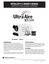
The included drain trap must be
installed to the dehumidifier. Use
PVC primer and cement to
connect the trap to the drain
outlet on the dehumidifier. The
drain outlet is located near the
On/Off toggle switch. Note
orientation of trap prior to
cementing. The high side of the
trap mates with the dehumidifier. The adjustable legs on
the dehumidifier must be disengaged approximately 1
7
⁄8”
to accommodate the trap. Loosen nuts before adjusting.
Complete the assembly by piping the trap to a drain. The
trap must be primed with water prior to start-up.
If the dehumidifier is installed in an attic or in an area
where flooding is a potential problem, it should be
installed in a secondary drain pan with a float switch. See
page 12 for float switch wiring.
If hanging the unit, use two unistruts to support the base
on the outside edges of the feet locations. There must
be at least 20” of clearance in front of one of the filter
access doors to allow removal of the filter.
3
DRAIN LINE
HANGING
DUCTING
The Aprilaire Dehumidifier is supplied with two
8” round collars. These are packaged with a drain
trap inside the unit behind the filter access panel.
Secure the collars with Four (4) 1-inch sheet metal
screws (not included). UL approved 8” diameter,
insulated flexible duct is recommended for all
connections. Rigid metal duct may also be used. The
duct should be capable of handling at least 2” w.c.
pressure. All joints and seams must be sealed.
Design airflow for the 1750 is 275 CFM @ 0.6” w.c.,
for the 1770 it is 500 CFM @ 0.8” w.c. This is
equivalent to approximately 70 ft. for the 1750 or
100 ft for the 1770 of 8” duct on the inlet and outlet
side of the dehumidifier. Elbows, turns and the static
pressure of the HVAC equipment will affect the
airflow through the dehumidifier.
•
For optimal moisture removal, airflow should be at or above
275 CFM for the 1750, 500 CFM for the 1770.
• The total static pressure across the 1750 must not exceed 0.8”
w.c., 1.5” w.c. for the 1770. Check all pressures with the HVAC
fan on.
• The outlet from the dehumidifier to the HVAC supply duct must be
located at least 6” downstream of the cooling coil to prevent air from
pulling moisture from the coil.
• If connected to HVAC ductwork, the dehumidifier inlet must be located
at least 6” upstream of the HVAC system air cleaner. This will prevent
any trapped particulates from being drawn into the dehumidifier.
• If UV Germicidal lamps are installed in the HVAC system, use
appropriate methods to protect the flexible duct from the UV light.
• To further reduce any sound that may be created by air movement,
install at least 5 feet of acoustical flexible duct on the outlet and inlet
of the dehumidifier.
2
1
/2”
1
/2”
Drain Outlet
Drain Trap
High Side
Low Side
FIGURE 1
90-961
3“ MIN
CLEARANCE FOR
ACCESS PANEL
20” MINUMUM
CLEARANCE FOR FILTER
(EITHER SIDE)
6" MIN CLEARANCE
FOR ACCESS PANEL
FILTER
TOP VIEW
FIGURE 2
90-970

4
CENTRAL INSTALLATION AND OPERATION
This installation is used when the HVAC equipment conditions the whole home or the area where dehumidification is needed.
Using an Aprilaire Central Dehumidifier in this application, in conjuction with the HVAC system, is the optimum solution for total,
year-round humidity control.
This installation is typically in attic or basement locations within the home. As shown in Figure 3 below, air is pulled from the
return duct, dehumidifed and returned to the supply duct.
1 – Backflow Damper
Duct Work
Thermostat Wire
REQUIRED COMPONENTS OPTIONAL COMPONENTS
6506 Ventilation Damper
24 VAC Transformer (10 VA minimum) for Ventilation Damper
8052 Outdoor Temperature Sensor
Float Switch
Model 70 Living Space Control
6“ MIN
RETURN
AIRFLOW
SUPPLY
AIRFLOW
6“ MIN
BACKFLOW DAMPER
OPTIONAL
OUTDOOR
AIR INTAKE
AIR CLEANERCOOLING COIL
HVAC UNIT
APRILAIRE
CENTRAL
DEHUMIDIFIER
OPTIONAL N.C.
VENT CONTROL DAMPER
(SEE PAGES 10-11)
FIGURE 3 – DUCTING
90-945

5
CENTRAL INSTALLATION AND OPERATION (CONTINUED)
THERMOSTAT HVAC EQUIPMENT
CONTROL
DEHUMIDIFIER
DAMPERS
Rf Y -WGhGs
Cf
VENT
HVAC EQUIP REMOTE
DEH B +A
R
C
W
YY
W
G
C
R
G
ODT
SENSORSWITCH
FLOAT
FIGURE 4 – WIRING
90-962
FIGURE 5 – SETTINGS
90-963
CYCLE TIME
TEST
60
OFF
0
MIN
MIN.
30
MIN.
ON
1 2 3 4
2 HOUR
3 HOUR
30 MIN.
1 HOUR
CYCLE PERIOD
4321
ON
VENT-TIMED
HVAC FAN
SYSTEM SETUP
ON
B
CONVERTIBLE
HVAC FAN
WHL HOUSE
VENT-AUTO
A
OFF
Standard Air Cycling Ventilation
OFF OFF OFF
See pages 10-11 See pages 10-11 See pages 10-11
OFF OFF OFF
OFF ON OFF
Standard Air Cycling Ventilation
OFF See pages 10-11 See pages 10-11
ON See pages 10-11 See pages 10-11
OFF See pages 10-11 See pages 10-11
OFF See pages 10-11 See pages 10-11
Standard Air Cycling Ventilation
OFF See pages 10-11 See pages 10-11
See page 10 for ventilation control wiring instructions.
See page 10 for air cycling wiring instructions.
See page 11 for float switch wiring instructions.

6
LOCALIZED INSTALLATION AND OPERATION
In this configuration, the central dehumidifier will pull air specifically from a local area, and is typically not ducted to the HVAC
equipment for the whole home conditioning and humidity control. Rather, this application will control humidity in a specific area,
typically a basement or crawlspace.
Power Supply Circuit
Drain Trap (included)
REQUIRED COMPONENTS OPTIONAL COMPONENTS
Duct Work
24 VAC Transformer (10 VA minimum) for Ventilation Damper
Thermostat Wire
6506 Ventilation Damper
8052 Outdoor Temperature Sensor
Grilles
Normally Closed Condensate Overflow Safety Switch
Model 70 Living Space Control
RETURN
AIRFLOW
OPTIONAL
OUTDOOR AIR INTAKE
AIR CLEANERCOOLING COIL
TO SUPPLY GRILLE OR
TO UNCONDITIONED SPACE
HVAC UNIT
OPTIONAL N.C.
VENT CONTROL
DAMPER
(SEE PAGES 10-11)
APRILAIRE
CENTRAL
DEHUMIDIFIER
SUPPLY
AIRFLOW
FROM RETURN GRILLE
OR UNCONDITIONED SPACE
FIGURE 6 – DUCTING
90-946

7
LOCALIZED INSTALLATION AND OPERATION (CONTINUED)
THERMOSTAT HVAC EQUIPMENT
CONTROL
DEHUMIDIFIER
DAMPERS
Rf Y -WGhGs
Cf
VENT
HVAC EQUIP REMOTE
DEH B +A
R
C
W
Y
Y
W
G
C
R
G
ODT
SENSORSWITCH
FLOAT
FIGURE 7 – WIRING
90-964
FIGURE 8 – SETTINGS
90-965
CYCLE TIME
TEST
60
OFF
0
MIN
MIN.
30
MIN.
ON
1 2 3 4
2 HOUR
3 HOUR
30 MIN.
1 HOUR
CYCLE PERIOD
4321
ON
VENT-TIMED
HVAC FAN
SYSTEM SETUP
ON
B
CONVERTIBLE
HVAC FAN
WHL HOUSE
VENT-AUTO
A
OFF
Standard Air Cycling Ventilation
OFF OFF OFF
See pages 10-11 See pages 10-11 See pages 10-11
ON ON ON
OFF ON OFF
Standard Air Cycling Ventilation
OFF See pages 10-11 See pages 10-11
ON See pages 10-11 See pages 10-11
OFF See pages 10-11 See pages 10-11
OFF See pages 10-11 See pages 10-11
Standard Air Cycling Ventilation
OFF See pages 10-11 See pages 10-11
See page 10 for ventilation control wiring instructions.
See page 10 for air cycling wiring instructions.
See page 11 for float switch wiring instructions.

8
CENTRAL / ZONED (CONVERTIBLE) INSTALLATION AND OPERATION
The Aprilaire central dehumidifier can be utilized not only for whole home humidity and comfort control, but also for addressing
specific zones or spaces that are high priority for humidity control. In this application, the central dehumidifier will control
humidity in the specific zone independently, as the higher priority, and then switch to the whole home when the HVAC equipment
is on/operating. Do Not use a Model 70 Living Space Control in this application.
NOTE: 1. 4522 Basement Kit includes 2 – 6508 N.C. Dampers, 2 – 6608 N.O. Dampers and a 24 VAC Transformer.
2. Running Constant fan on will prevent proper function in this mode.
2 – 6508 Normally Closed Power Open Damper
2 – 6608 Normally Open Power Closed Damper
Duct Work
24 VAC Transformer (40 VA minimum)
Thermostat Wire
REQUIRED COMPONENTS OPTIONAL COMPONENTS
6506 Ventilation Damper
24 VAC Transformer (10 VA minimum) for Ventilation Damper
8052 Outdoor Temperature Sensor
Normally Closed Condensate Overflow Safety Switch
6“ MIN
RETURN
AIRFLOW
6“ MIN
AIR CLEANERCOOLING COIL
HVAC UNIT
APRILAIRE
CENTRAL
DEHUMIDIFIER
N.O. DAMPER
SUPPLY
AIRFLOW
N.O. DAMPER
N.C. DAMPER
N.C. DAMPER
RETURN FROM
UNCONDITIONED
SPACE
SUPPLY TO
UNCONDITIONED
SPACE
OPTIONAL
N.C. DAMPER
OPTIONAL
OUTDOOR AIR
INTAKE
FIGURE 9 – DUCTING
90-947

9
CENTRAL / ZONED (CONVERTIBLE) INSTALLATION AND OPERATION (CONTINUED)
THERMOSTAT HVAC EQUIPMENT
DEHUMIDIFIER SYSTEM DAMPERS
CONTROL
DEHUMIDIFIER
TRANSFORMER
(40 VA min)
24 VAC
DAMPERS
Rf Y -WGhGs
Cf
VENT
HVAC EQUIP. REMOTE
DEH B +A
R
C
W
YY
W
G
C
R
G
ODT
SENSORSWITCH
FLOAT
WIRE NUT
FIGURE 10 – WIRING
9
0-966
FIGURE 11 – SETTINGS
90-965
CYCLE TIME
TEST
60
OFF
0
MIN
MIN.
30
MIN.
ON
1 2 3 4
2 HOUR
3 HOUR
30 MIN.
1 HOUR
CYCLE PERIOD
4321
ON
VENT-TIMED
HVAC FAN
SYSTEM SETUP
ON
B
CONVERTIBLE
HVAC FAN
WHL HOUSE
VENT-AUTO
A
OFF
Standard Air Cycling Ventilation
OFF OFF OFF
OFF OFF OFF
ON ON ON
OFF ON OFF
Standard Air Cycling Ventilation
OFF See pages 10-11 See pages 10-11
ON See pages 10-11 See pages 10-11
OFF See pages 10-11 See pages 10-11
OFF See pages 10-11 See pages 10-11
Standard Air Cycling Ventilation
OFF See pages 10-11 See pages 10-11
See page 10 for ventilation control wiring instructions.
See page 10 for fan cycling wiring instructions.
See page 11 for float switch wiring instructions.

10
A. Set the 1/2, 1, 2 or 3 hour period by setting the CYCLE PERIOD dip switches (Figure 13) to
determine how often the dehumidifier should look to cycle the HVAC fan. The factory default
setting is 1 hour.
B. The CYCLE TIME dial determines how long during every Cycle Period the HVAC fan should
operate. Adjust the dial from OFF to between 1 and 60 minutes. This will give you HVAC fan
operation from 1 to 60 minutes every 1/2, 1, 2 or 3 hours. A call for heat, cooling or fan from
the HVAC equipment will often satisfy the run time requirement. If not, the dehumidifier will
turn on the HVAC fan to assure that the Cycle Time is met. For example: If the building
requires air cycling of 20 minutes every two hours set the CYCLE PERIOD Dip Switch
for 2 hours to ON, turn OFF the 1 HOUR Dip Switch and rotate the CYCLE TIME to 20
minutes. If the HVAC equipment has only run for 10 minutes, the dehumidifier will turn
on the HVAC fan for 10 minutes at the end of the 2 hours to assure the fan cycling time.
FIGURE 14
90-783C
FIGURE 13
ON
1 2 3 4
2 HOUR
3 HOUR
30 MIN.
1 HOUR
CYCLE PERIOD
90-783C
CYCLE TIME
TEST
60
MIN.
OFF
0
MIN
MIN.
30
MIN.
(shown set
to 1 hour)
FIGURE 15
4321
ON
VENT-TIMED
HVAC FAN
SYSTEM SETUP
ON
B
CONVERTIBLE
HVAC FAN
WHL HOUSE
VENT-AUTO
A
OFF
90-969
(shown set to
30 minutes)
VENTILATION / AIR CYCLING SETTINGS
The Aprilaire Dehumidifier has the option
to monitor HVAC heating, cooling and fan
calls to assure the HVAC fan has
operated a predetermined amount of
time each 1/2, 1, 2 or 3 hours. The
dehumidifier can also open a normally
closed damper in an outdoor air intake to
ventilate during this predetermined
amount of time. This feature will
function even if the dehumidifier is
turned off at the dehumidifier or Model
70 Occupied Space Control. The only way
to disable this feature is by turning the
Cycle Time setting to OFF or turning
power off at the On/Off switch.
HVAC EQUIPMENTTHERMOSTAT
WIRE NUT
DEHUMIDIFIER
CONTROL
24 VAC
(10 VA min)
TRANSFORMER
DAMPER
VENTILATION
OPTIONAL
G
R
C
G
W
YY
W
C
R
A +BDEH
REMOTEHVAC EQUIP.
VENT
Cf
Gs Gh W -YRf
DAMPERS
OPTIONAL OUTDOOR
TEMPERATURE SENSOR
(Model 8052)
SENSOR
ODT
SWITCH
FLOAT
FIGURE 12
90-968
A. If using the Ventilation Damper, determine if the ventilation should be restricted based on
outdoor temperature. Set the VENT-AUTO / VENT-TIMED dip switch to VENT-AUTO
(see Figure 15) to prevent opening the ventilation damper if the outdoor air is above 100°F,
below 0°F or except with a heat call between 20°F and 0°F. In the VENT-TIMED setting the
ventilation damper is activated regardless of outdoor conditions. Note: The Outdoor
Temperature Sensor (Model 8052) must be installed for this to work.
AIR CYCLING
OUTSIDE AIR VENTILATION

11
VENTILATION / AIR CYCLING SETTINGS (CONTINUED)
• An Aprilaire
®
Normally-Closed Damper (Model 6506) should
be installed in the outside air intake. It should be wired to
the terminals labeled “VENT DAMPER” on the dehumidifier
control board. Follow all installation instructions supplied
with the damper. Refer to each installation for ducting.
• The Outdoor Temperature Sensor (Model 8052) should be
installed outside in a shaded location (Figure 16) or in an
outside air intake duct, but no more than 3 feet from the
outside wall (Figure 17).
• The Outdoor Temperature Sensor is not affected by wire
length. However, do not route the wire alongside wires
carrying high voltage (115 VAC or greater), as interference may occur.
• Connect the wires from the sensor to the terminals labeled “ODT SENSOR” on the dehumidifier.
See Figure 12 for terminal locations.
B. This installed option allows outside air to be combined with
the fan cycling feature from the dehumidifier, provided the
outside air temperature is in the acceptable range (0-100°F).
This will allow the homeowner to receive the proper
ventilation year round.
Note: The dehumidifier can control the HVAC fan to
provide fan cycling, regardless of whether or not an outdoor
ventilation duct is installed.
NORTH, EAST
OR WEST SIDE
O
F HOME
OUTDOOR
TEMPERATURE
SENSOR
S
ENSOR
SENSOR
BRACKET
ABOVE EXPECTED
S
NOW LINE
OUTDOOR
TEMPERATURE SENSOR
LEADS
36" MAX.
CENTER LINE
OUTSIDE WALL
B2202617-D
B2202617-E
FIGURE 16
FIGURE 17
STEP 1: CALCULATE THE VENTILATION REQUIREMENT
A. The MINIMUM ventilation requirement is calculated using ASHRAE 62.2-2004.
ASHRAE Airflow In CFM = [House Area in Sq Ft x 0.01] + [No. Bedrooms +1 x 7.5]
Use the Number of Bedrooms (Plus 1) or the Number of Occupants, Whichever Is Larger
B. Table 1 shows calculated airflow values
at the nearest 5 cfm.
HOUSE
SQ FT
TABLE 1 – Minimum CFM Per Number Bedrooms
2 3 4 5 6
1000 35 40 50 - - - - - -
1500 40 45 55 60 70
2000 45 50 60 65 75
2500 50 55 65 70 80
3000 55 60 70 75 85
3500 - - - - - - 75 80 90

12
TABLE 2 – AIRFLOW DELIVERY VS NEGATIVE STATIC PRESSURE AS MEASURED FOR RETURN DUCT OR PLENUM (IN WC)
DUCT
LENGTH
0.05 0.10 0.15 0.20 0.25 0.30
FLEX PIPE FLEX PIPE FLEX PIPE FLEX PIPE FLEX PIPE FLEX PIPE
10 FT 60 65 85 90 105 110 120 125 135 140 150 160
20 FT 55 60 80 85 100 105 115 120 130 135 140 150
30 FT 50 55 75 80 95 100 110 115 125 130 130 140
TABLE 3
Airflow Required >>
20 30 40 50 60 70 80 90 100
Airflow Delivered KNOB SETTINGS (in minutes) FOR AIRFLOW DELIVERED vs AIRFLOW REQUIRED (1 HR CYCLE)
60
20 30 40 50 60
70 80 90 100
80
15 25 30 40 45 55 60
70 75
100
15 20 25 30 35 40 50 55 60
120
10 15 20 25 30 35 40 45 50
140
10 15 15 20 25 30 35 40 45
160
10 10 15 20 25 25 30 35 40
90-968A
STEP 2: DETERMINE THE FRESH AIR DELIVERY RATE
A. Measure the negative static pressure of the return system and consult Table 2 below for approximate inlet airflow.
An airflow measuring device (Nailor-Hart, etc.) will give the airflow exactly.
B. For the table below, the flex duct is laid loose with 2 wide 90° bends, and the damper is fully open. For the rigid pipe, the
values are based on two 90° elbows, and the damper is fully open. For both cases the air intake is through a metal vent hood
with a bird screen. Adjust airflow accordingly for variations.
STEP 3: DETERMINE CYCLE TIME
A. The Cycle Period determines how often the dehumidifier should look to ventilate. This is
variable from 30 minutes to 3 hours (see Figure 13). Once the ventilation requirement is met,
ventilation will not occur until the start of the next Cycle Period.
B. The CYCLE TIME dial determines how long during every Cycle Period the damper will open
and ventilation will occur. The dial can be adjusted from OFF to between 1 to 60 minutes (see
Figure 14). This will give outdoor air ventilation and HVAC fan operation from 1 to 60 minutes
every Cycle Period.
C. Refer to Table 3 to determine the Cycle Time setting based on airflow delivered and airflow
required. The values listed in the table are for a 1 hour Cycle Period. For a 2 hour Cycle Period,
the Cycle Time would be set to twice the value (if in the white area of the table). The values
in the black portion of the table cannot be set due to the 60 minute Cycle Time limit.
FLOAT SWITCH
If the dehumidifier is installed in an attic or another location requiring
leak protection, the unit should be placed in a drain pan with a
normally closed condensate overflow safety switch (also known as a
float switch). The float switch should be wired to the float switch
terminals on the dehumidifier control board. See Figure 18. Remove
the jumper at the float switch terminals. The compressor is disabled
when the float switch is open. The dehumidifier will continue to
ventilate when the float switch is open.
CLOSED FLOAT SWITCH
LOW VOLTAGE NORMALLY
FLOAT
SWITCH SENSOR
ODT
FIGURE 18
FIGURE 14
90-783C
FIGURE 13
4321
ON
T
IMED
BLOWER
SYSTEM SETUP
ON
REMOTE
L
OCAL
BLOWER-OFF
H
OUSE
V
ENT-AUTO
R
EMOTE-OFF
ON
1 2 3 4
2 HOUR
3 HOUR
30 MIN.
1
HOUR
CYCLE PERIOD
CYCLE TIME
TEST
60
MIN.
OFF
0
MIN
MIN.
30
MIN.
90-783C
4321
ON
TIMED
BLOWER
SYSTEM SETUP
ON
REMOTE
L
OCAL
BLOWER-OFF
H
OUSE
VENT-AUTO
REMOTE-OFF
ON
1 2 3 4
2 HOUR
3 HOUR
30 MIN.
1 HOUR
CYCLE PERIOD
CYCLE TIME
TEST
60
MIN.
OFF
0
MIN
MIN.
30
MIN.
(shown set
to 1 hour)
(shown set to
30 minutes)

13
DIP SWITCH DEFINITIONS
A-B (SYSTEM SETUP SWITCH #1):
H
VAC FAN – OFF/ON (SYSTEM SETUP SWITCH #2):
WHL HOUSE / CONVERTIBLE (SYSTEM SETUP SWITCH #3):
VENT-AUTO / VENT-TIMED (SYSTEM SETUP SWITCH #4):
Reserved for future use.
Determines if the HVAC fan activates during a call for
dehumidification.
HVAC FAN-OFF position. The dehumidifier will not
activate the HVAC fan during a call for
dehumidification; it will however activate the HVAC fan
for air cycling and ventilation.
HVAC FAN-ON position. The dehumidifier will
activate the HVAC fan during a call for
dehumidification as well as for air cycling and
ventilation.
Default is HVAC FAN-OFF.
Determines if ventilation is restricted based on outdoor temperature.
VENT-AUTO position. The dehumidifier will measure the outdoor
temperature (through sensor, part # 8052) to determine if the
ventilation damper will open. If the outside temperature is above
100°F or below 0°F the dehumidifier will not actuate the ventilation
damper terminals (VENT DAMPER). If the outside temperature is
between 0°F - 20°F, the dehumidifier will only actuate the ventilation
damper terminals (VENT DAMPER) when the HVAC system is making
a call for heat. The dehumidifier will energize the HVAC fan whether
or not the ventilation damper opens.
VENT-TIMED position. The dehumidifier will actuate the ventilation
damper terminals (VENT DAMPER) regardless of the outdoor temperature.
The default position is VENT-AUTO.
Determines when the dampers are powered open or closed.
CONVERTIBLE position. This is used for zoned dehumidification.
The damper (DEH) terminals are actuated when the HVAC equipment
is making a call for heat, cool or fan and the dehumidifier is making
an internal blower call for air sampling or dehumidification.
WHL HOUSE position. This is used for central dehumidification. The
damper (DEH) terminals are actuated any time the dehumidifier is
making an internal blower call for air sampling or dehumidification.
The default position is WHL HOUSE.
SYSTEM CHECKOUT
1. Check the wiring to the HVAC equipment.
2. Rotate the main control knob clockwise to the “TEST” position.
3. If all is set up properly, the dehumidifier blower will turn on. The compressor will turn on after the dehumidifier blower has run
for 3 minutes. After 1 minute the dehumidifier blower and compressor will shut off (“TEST” mode only).
4. If the dehumidifier blower does not activate in TEST mode, refer to the Troubleshooting Guide.
5. For ventilation (optional) test, be sure that 24 VAC is applied in series with the Aprilaire
®
Normally-Closed Damper
(Model 6506) and connected to the “VENT DAMPER” terminals on the dehumidifier control.
6. Rotate the “CYCLE TIME” potentiometer clockwise to the “TEST” position.
7. If all is set up properly, the HVAC blower will turn on and the ventilation damper will open. Both should be audible to the
installer. The HVAC blower will remain on and the ventilation damper will remain open for 1 minute or until the dial is turned
from the “TEST” position, whichever happens first. DO NOT leave the CYCLE TIME in TEST.
8. If the optional ventilation damper or HVAC blower does not activate in TEST mode, refer to the Troubleshooting Guide.

14
TROUBLESHOOTING GUIDE
SYMPTOM TROUBLESHOOTING PROCEDURE / POSSIBLE REASON
Dehumidifier is not
draining properly.
• Check drain trap to be sure it is clear.
• Check drain line for continuous slope.
• Confirm trap is properly installed and primed.
Dehumidifier is producing
hot air.
• Reheat of outgoing air will cause a temperature increase across the dehumidifier,
which is normal.
• Unit will possibly run continuously initially. After unit has “dried” home,
dehumidifier will cycle, reducing load.
HVAC fan does not turn
on when CYCLE TIME dial is
in “TEST” mode.
• Make sure there is power to the HVAC equipment.
• Check the wiring diagram for the R, C, W, Y, GH, and GS at the HVAC equipment,
thermostat, and the dehumidifier.
• Make sure the sensor is connected to the Outdoor Temperature Sensor terminals
or the System Setup block is set to “TIMED” mode.
• Check the voltage across the R and C terminals at the dehumidifier. Voltage
should be 18 VAC minimum - 30 VAC maximum.
• In “TEST” Mode, the HVAC fan will activate for 4 minutes, DO NOT LEAVE IN
TEST MODE AS DEHUMIDIFIER WILL NOT OPERATE.
Dehumidifier Blower is running,
but no airflow.
• Normally Open Damper was used instead of Normally Closed Damper in backflow.
Damper needs to be switched.
• Total HVAC system static is higher than 0.8” w.c.
Dehumidifier not adequately
dehumidifying.
• Unit will need time to “dry” materials in home before effectively changing RH.
• Too little airflow through dehumidifier.
• Total HVAC system static is higher than 0.8” w.c.
• Compressor is not turning on.
• System undercharged.
LED CODES
Green LED
Activity Status
ON Solid Compressor ON
Blinking 1 second on, 1 second off Sampling
Blinking 1/2 second ON, 1/2 second OFF Defrosting
Red LED
Activity Status
1 Blink every 5 seconds The RH sensor is having problems
2 Blink every 5 seconds The temperature sensor is opened or shorted
3 Blink every 5 seconds The Model 70 fails to respond after 3 consecutive attempts
4 Blink every 5 seconds The refirgerant charge has been detected as low
5 Blink every 5 seconds The temperature sensor is out of the operating range
6 Blink every 5 seconds The frost sensor is opened or shorted
7 Blink every 5 seconds The float switch has opened
Test Mode
At the end of test mode (3 minutes of DEH Fan + 1 minute of Compressor ON & DEH Fan), the Red and Green LEDs will turn ON and OFF alternately until the
knob has been turned away from “TEST”.

15
TROUBLESHOOTING GUIDE (CONTINUED)
The dehumidifier damper does
not open in “TEST” Mode.
• Follow all of the system checkout procedures.
• Check the wiring diagram for the damper and 24 VAC transformers.
Fan cycling operates
continuously after the dial
is taken off “TEST” mode.
• If the HVAC equipment is making a Heat or Cool call, or the fan is in Continuous
Operation, fan cycling will remain on until the requirement set by the CYCLE
PERIOD dip switch and knob is met.
• If the interval is set at 1 HOUR and the Cycle Time is set at 60 minutes, fan
cycling will be on continuously. Change the setting to a lower amount if this is
not desired.
TROUBLESHOOTING GUIDE (CONTINUED)
SYMPTOM TROUBLESHOOTING PROCEDURE / POSSIBLE REASON
The ventilation damper
does not open when the
HVAC fan is active.
• The damper will not open if the Cycle Time within the current period has already
been met. For instance if the Cycle Time is set to 5 minutes and the control has
already ventilated for 5 minutes in that interval, the damper will remain closed.
• If using the Outdoor Temperature Sensor, check
that it is installed in the Outdoor Air Intake a
maximum of 3 feet from the outside wall, or on
the North, East or West side of the house.
(Not in direct sunlight.) If the outdoor
temperature is below 0°F or above 100°F, the
damper will remain closed.
• If using the outdoor temperature sensor, verify
that it is reporting an accurate resistance.
Remove the Outdoor Temperature Sensor leads
from ODT Sensor terminals and check the
resistance. Compare the reading with the
resistance shown in Table 4.
The HVAC fan turns on unexpectedly. • The control will turn on the fan as needed to meet the air cycling requirements
determined by the Cycle Time and Cycle Period settings.
The dehumidifier does not run. • Follow all of the system checkout procedures.
• Check that the power switch on the dehumidifier is on.
• Check that the circuit breaker is not tripped. The dehumidifier requires a
minimum of 8 amps. The dehumidifier should be placed on a dedicated
15 amp circuit or a lightly loaded circuit.
The compressor never runs. • If a float switch is not installed, confirm that the jumper is installed at the
float switch terminals on the control board.
• If a float switch is installed, confirm that the float switch is not open.
Outdoor
Temperature
-30˚F
-20˚F
-10˚F
0˚F
10˚F
20˚F
30˚F
40˚F
50˚F
60˚F
70˚F
80˚F
90˚F
100˚F
Resistance
229,500 OHMS
162,500 OHMS
116,500 OHMS
84,500 OHMS
62,000 OHMS
46,000 OHMS
34,500 OHMS
26,000 OHMS
20,000 OHMS
15,500 OHMS
12,000 OHMS
9,500 OHMS
7,500 OHMS
6,000 OHMS
TABLE 4

10007791 10.07
B2204536A
DEHUMIDIFIER SEQUENCE OF OPERATION
IF THE DEHUMIDIFIER IS NOT WIRED TO THE HVAC EQUIPMENT, THE DEHUMIDIFIER WILL SAMPLE AT THE END OF THE
CYCLE PERIOD.
With 4 minutes left in the Cycle Period, the dehumidifier will turn on the dehumidifier blower for 3 minutes. During this time the
temperature and relative humidity are measured and the dewpoint is calculated. If the dewpoint is higher than the setting at the
Control Knob then the dehumidifier compressor will turn on and the dehumidifier will run until it reaches set point.
After reaching the set point, the dehumidifier will not sample again until the end of the next Sample Period.
For example, if the Sample Period is set for 1 hour, the dehumidifier will sample at the end of the hour. Once the dehumidifier
reaches set point and shuts off, the dehumidifier will not sample again until the end of the next hour.
IF THE DEHUMIDIFIER IS WIRED INTO THE HVAC EQUIPMENT, THE DEHUMIDIFIER WILL SAMPLE THE FIRST TIME THE HVAC
EQUIPMENT RUNS IN THE CYCLE PERIOD OR AT THE END OF THE CYCLE PERIOD IF THE HVAC EQUIPMENT DOES NOT RUN.
For example, if the Cycle Period is set to 1 hour and the air conditioner starts 15 minutes into that hour, the dehumidifier will
sample when the air conditioner starts. Once the dehumidifier begins dehumidifying, it will run until set point is reached. If the
dehumidifier samples and determines that dehumidification is not needed, it will not sample again until the next Cycle Period.
DAMPER SEQUENCE OF OPERATION
In the Central/Zoned installation 4 motorized dampers are used to control the airflow through the dehumidifier. The dampers are
energized when the HVAC equipment is running. This means that when the HVAC equipment is running, the dampers are in the
central position. When the HVAC equipment is not running, the dampers are in the zoned position.
VENTILATION OR AIR CYCLING SEQUENCE OF OPERATION
If the dehumidifier is providing outdoor air ventilation or air cycling, it is monitoring the HVAC equipment to provide the amount
of HVAC fan run time that has been set by the Cycle Time during the Cycle Period.
If an outdoor air damper has not been installed then the dehumidifier is providing air cycling. The dehumidifier will monitor the
HVAC system and if the system has not run for the specified Cycle Time within the Cycle Period, the dehumidifier will energize
the HVAC fan through the G terminal to provide the desired amount of fan run time.
For example, if the Cycle Time is set for 10 minutes and the Cycle Period is set for 1 hour then the dehumidifier will provide
10 minutes of air cycling or outdoor air ventilation. If the HVAC system runs for 5 minutes during this hour then the dehumidifier
will energize the fan for an additional 5 minutes.
If an outdoor air damper has been installed, then the Aprilaire dehumidifier is providing outdoor air ventilation. The dehumidifier
will open the outdoor air damper whenever the HVAC system is running, up to the amount of time specified by the Cycle Time.
The dehumidifier will energize the HVAC fan and open the outdoor air damper to provide the desired ventilation time if the HVAC
system has not run for the specified Cycle Time. During ventilation, the dehumidifier blower will operate and the unit will
dehumidify if necessary.
If an Outdoor Temperature Sensor has been installed, then the dehumidifier will use the outdoor temperature to determine if the
outdoor air damper is to be opened. If the outdoor temperature is above 100°F the damper will not open. If the temperature is
between 20°F and 0°F the damper will only open with a heat call. If the outdoor temperature is below 0°F, the damper will not
open. If the Outdoor Temperature Sensor is not installed then the temperature is not considered in opening the damper.
RESEARCH PRODUCTS CORPORATION
P.O. BOX 1467 • MADISON, WI 53701-1467 • PHONE: 800/334-6011 • FAX: 608/257-4357 • www.aprilairecontractor.com
/