Page is loading ...

KA207F/00/en/03.06
71022693
Valid as of software version:
V 02.03
GPE communication protocol
Tank Side Monitor NRF590
Inventory Control


NRF 590 - GPE communication protocol Table of contents
3
Table of contents
1 Introduction . . . . . . . . . . . . . . . . . . . . . 4
2 Implementation . . . . . . . . . . . . . . . . . . 4
2.1 GPE Modes (Device Types) . . . . . . . . . . . . . . . . . . . 4
2.2 GPE Functions . . . . . . . . . . . . . . . . . . . . . . . . . . . . 4
3 Configuration . . . . . . . . . . . . . . . . . . . . 5
3.1 Address . . . . . . . . . . . . . . . . . . . . . . . . . . . . . . . . . . 5
3.2 Configuration settings . . . . . . . . . . . . . . . . . . . . . . . 5
4 Measured values . . . . . . . . . . . . . . . . . 8
4.1 Measured Value Ranges . . . . . . . . . . . . . . . . . . . . . . 8
4.2 Measured Value Error Handling . . . . . . . . . . . . . . . . 8
5 GPE Message Formats . . . . . . . . . . . . . 9
5.1 Physical Layer . . . . . . . . . . . . . . . . . . . . . . . . . . . . . 9
5.2 Request Message . . . . . . . . . . . . . . . . . . . . . . . . . . . 9
5.3 Reply Message . . . . . . . . . . . . . . . . . . . . . . . . . . . . . 9

Introduction NRF 590 - GPE communication protocol
4
1Introduction
This protocol guide explains the operation of the GPE protocol implemented in the Endress+Hauser
Tank Side Monitor NRF590.
2 Implementation
The implementation of the GPE protocol for the Tank Side Monitor provides a standard form of
digital communication via a current loop. An effort has been made to parallel current
implementations to the greatest extent possible, so that the Tank Side Monitor communicates with
existing GPE masters.
Check compatibility carefully to ensure that the Tank Side Monitor is properly configured for the
data format expected by the host system or computer. Exceptions made because of the unique
requirements of the Tank Side Monitor application have been noted.
!Note!
This is no guarantee, however, that the interpretation made here will be the same as that followed
by the GPE master.
The GPE protocol supports three modes of communication and within each mode four commands
2.1 GPE Modes (Device Types)
2.2 GPE Functions
Device Type (23111) Description
Short Reply New GPE Protocol, used by devices which incorporporate a microcontroller
Long Reply Old GPE Protocol, used by older hardware controlled systems
1mm Reply Expanded protocol for higher measurement resolution
Function Description
LT Used to obtain Level and Temperature
LTA Used to obtain Level, Temperature and 4 ... 20mA VAlue
LTC Used to close a discrete contact and obtain Level and Temperature
LTO Used to open a discrete contact and obtain Level and Temperature

NRF 590 - GPE communication protocol Configuration
5
3Configuration
The GPE port on the Tank Side Monitor must be configured to establish communications. The local
Tank Side Monitor display or ToF Tool allow the user to set up the GPE parameters needed for a
correct communication with a GPE master unit.
3.1 Address
Tank Side Monitor addresses provide unique identification for the host. The Tank Side Monitor
address is configurable through the local display or ToF tool. This address may range from 0 to 99
and must be unique for each GPE device on a loop. A Tank Side Monitor unit will ONLY answer to
a request that contains the same Address or Communication ID that the unit is set to.
3.2 Configuration settings
In order for successful communication on a GPE loop a number of configuration settings must be
made to match the configuration of the loop.
3.2.1 Summary of Configuration Parameters
A summary of the configuration information required by the Tank Side Monitor is shown in the
following table.
3.2.2 Description of Configuration Parameters
Loop Number (23107)
The loop parameter forms a second part of the identification of a message, if enabled (see Loop Mode
parameter) it will be compared with the value in the received message. The message will only be
processed if they match.
ID (9211)
This is a unique number for this device on the GPE loop, only when the Tank Side Monitor receives
a request message with this number is a response generated.
Baudrate (9212)
Specifies the communication speed used on the GPE loop.
Configuration parameter Valid Entries Default
ID 0 ... 99 1
Baudrate 250 ... 350 baud 300
Type • Short Reply
• Long Reply
•1mm Reply
Short Reply
Loop Mode • Not Checked
•Checked Not Checked
Loop Number 0 ... 4 0
Long Reply Type • Type 1
• Type 2
• Type 3
Type 1
4-20mA Ref List of TSM parameters IS AI Input Value
Contact Ref DIO#x or Alarms IS DI#1 Input Value
Conv Fact Adj 0.5 ... 1.5 1.0

Configuration NRF 590 - GPE communication protocol
6
Type (9213)
Specifies the format of the response generated by the Tank Side Monitor.
Loop Mode (9214)
Indicates if the loop value within the request message should be evaluated or not. If not then the
Tank Side Monitor will respond to all messages with it’s ID number no matter which loop number
is in the request.
Long Reply Type (9224)
The value determines how the "Level 0.1" value is encoded into the long reply "Fine Level 0.1" and
"Coarse Level 0.1" digits. See "Long Reply Additional Information".
4-20mA Ref (9221)
This parameter is used to connect a calculated or measured value within the Tank Side Monitor to
this part of the response message. There are specific limitations on the range of values which can be
transmitted.
Contact Ref (9222)
This parameter selects the discrete output which will be controlled by the LTC & LTO command.
The status of this output is also returned as part of the Tank Side Monitors response message.

NRF 590 - GPE communication protocol Configuration
7
Conversion Factor Adjust (9223)
This parameter allows the level value transmitted on the GPE bus to be adjusted to compensates for
inaccuracies in control room equipment during unit conversion, for example.
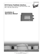
Example
L00-NRF590-02-00-00-en-002
In this example, the NRF will have to be set to "feet" as the GPE loop is working in "feet". The NRF
will convert the level from the FMR using the correct conversion factor (1ft = 0.3048m), however
the GPE Loop Interface to the Control System may use an inaccurate conversion (e.g. 1ft = 0.3m).
To compensate for this inaccuracy, the "Conversion Factor Adjustment" (CFA) value can be set as
follows:
The NRF will then multiply its value in by this adjustment value before sending on the GPE bus
(Note, only the value sent on the bus is affected, the displayed value and value used for internal
calculations will not be changed by this paramater). The control room will then after conversion
have the correct value.
GPE Loop
"feet"
FMR
"meters"
NRF GPE Loop
Interface
Control Syste m
"meters"
CFA = accurate conversion factor / inaccurate conversion factor
= 0.3048/0.3
= 1.016
CFA = 1.000 CFA = 1.016 Remarks
FMR Value 2.540 m 2.540 m
NRF Displayed Value 8.333 ft 8.333 ft 1 ft = 0.3048 m
Value Sent to GPE Loop 8.333 8.466 = value * CFA
Control System Value 2.500 m 2.540 m 1 ft = 0.3 m

Measured values NRF 590 - GPE communication protocol
8
4 Measured values
4.1 Measured Value Ranges
The GPE response will contain between 2 and 3 measurement values, level, temperature and 4-
20mA value (LTA function only). Depending on the setting of the GPE parameters these values are
subject to the following limits.
4.2 Measured Value Error Handling
The following error handling rules are applied to all values returned in the GPE message.
1. If a value (level, temperature or 4-20mA) is below the minimum value then the minimum
value is returned.
2. If a value (level, temperature or 4-20mA) is above the maximum value then the maximum
value is returned.
3. If a value (level, temperature or 4-20mA) is undefined, invalid or offline the maximum is
returned.
Measurement
Value1
1) Resolution of all values is +/- one significant figure of the specific units, except level in type "short"
Reply Type
Description of Value
Short Long 1mm
Level 0.0002 ...
+199.995
2) The smallest unit of level increment is 0.005 of the specific units.
0.000 ...
+199.999
0.0000 ...
+199.9999
Value of Tank Corrected Level in current
Tank Level Units
Temperature -799 ...
+799
-799 ...
+799
-799.9 ...
+799.9
Tank Temp in current Tank Temp Units
4-20mA -19.99 ...
+19.99
-19.99 ...
+19.99
-1999.99 ...
+1999.99
Value of linked parameter in its current
units3
3) If the units are ft-in-16 or ft-in-8 the value of Level is in decimal ft.

NRF 590 - GPE communication protocol GPE Message Formats
9
5 GPE Message Formats
5.1 Physical Layer
The GPE communication takes place on a 20mA current loop. Bits are represented by current
flowing or not in the loop. These bits are generated and interpreted by a standard serial
communication controller (UART) running at the selected baudrate and communication settings.
Each group of bits together with their start, stop and parity represents an ASCII character forming
the elements of the messages. Within each character bits 0 to 3 are under to encode decimal values,
while the remaining 3 or 4 bits are used to provide additional information.
5.2 Request Message
The request is a sequence of three characters sent from the control room, these characters encode
the loop number and the device whose data is requested as well as which GPE function is to be
executed.
The value of the upper bits in the 2nd and 3rd byte describes the GPE function to be executed:
5.3 Reply Message
The reply from the Tank Side Monitor depends on the function requested by the control room and
the Device Type configuration parameter of the Tank Side Monitor.
5.3.1 Reply to Functions LT, LTC and LTO
The reply from the Tank Side Monitor is the same for all three functions LT, LTC & LTO, the upper
bits of the characters are all 0x30. However the replies do differ depending on the Device Type
selected.
Byte Bits 0-3 Bits 4-6 or7 Description
1st 0 to 4 0x20 Loop Number
2nd 0 to 9 0x40 ... 0x70 Address 1
3rd 0 to 9 0x40 ... 0x70 Address 10
Bits 4-6 or7 Function Description
0x40 LTA Return Level, Temperature and 4-20mA Value
0x50 LT Return Level and Temperature
0x60 LTC Close the discrete output and return level and temperature
0x70 LTO Open the discrete output and return level and temperature
Reply Byte Reply Type
Short Long 1mm
1st Address 1 Address 1 Address 1
2nd Address 10 Address 10 Address 10
3rd Level 0.01 Fine Level 0.001 Level 0.0001
4th Level 0.1 Fine Level 0.01 Level 0.001
5th Level 1 Fine Level 0.1 Level 0.01
6th Level 10 Coarse Level 0.1 Level 0.1

GPE Message Formats NRF 590 - GPE communication protocol
10
5.3.2 Reply to Functions LTA
The reply from the Tank Side Monitor for the function LTA differs not only by the contents but also
by the value of the upper bits of the characters which are all 0x20. However the replies do differ
depending on the Device Type selected.
7th Level 1001Coarse Level 1 Level 1
8th Temp 1 Coarse Level 10 Level 10
9th Temp 10 Coarse Level 1002Level 100
10th Temp 1003Temp 1 Temp 0.1
11th Temp 10 Temp 1
12th Temp 1003Temp 10
13th Temp 1003
1) This level value can only be 0 or 1. Bit 2 if set indicates an additional 0.005 should be added to the value. Bit 3 if set
indicates the discrete output is closed.
2) This level value can only be 0 or 1. Bit 3 if set indicates the discrete output is closed.
3) This temperature value can only be between 0 and 7. Bit 3 if set indicates the value is a –ve temperature.
Reply Byte Reply Type
Short Long 1mm
1st Address 1 Address 1 Address 1
2nd Address 10 Address 10 Address 10
3rd Level 0.01 Fine Level 0.001 Level 0.0001
4th Level 0.1 Fine Level 0.01 Level 0.001
5th Level 1 Fine Level 0.1 Level 0.01
6th Level 10 Coarse Level 0.1 Level 0.1
7th Level 1001
1) This level value can only be 0 or 1. Bit 2 if set indicates an additional 0.005 should be added to the value. Bit 3 if set
indicates the discrete output is closed.
Coarse Level 1 Level 1
8th Temp 1 Coarse Level 10 Level 10
9th Temp 10 Coarse Level 1002
2) This level value can only be 0 or 1. Bit 3 if set indicates the discrete output is closed.
Level 100
10th Temp 1003
3) This temperature value can only be between 0 and 7. Bit 3 if set indicates the value is a –ve temperature.
Temp 1 Temp 0.1
11th 4-20mA 0.01 Temp 10 Temp 1
12th 4-20mA 0.1 Temp 1003Temp 10
13th 4-20mA 1 4-20mA 0.01 Temp 1003
14th 4-20mA 104
4) This 4-20mA value can only be 0 or 1. Bit 1 if set indicates the value is a –ve one.
4-20mA 0.1 4-20mA 0.01
15th 4-20mA 1 4-20mA 0.1
16th 4-20mA 1044-20mA 1
17th 4-20mA 10
18th 4-20mA 100
19th 4-20mA 10004
Reply Byte Reply Type
Short Long 1mm

NRF 590 - GPE communication protocol GPE Message Formats
11
5.3.3 Long Reply Additional Information
In the long reply the level is sent as two components, this was used due to the mechanical nature
of the old devices which employed this protocol. When the Tank Side Monitor is used in this mode,
these values are as follows:
The Long Reply Type parameter allows you to adjust the layout so when the two values (Fine &
Coarse) are combined in the control system a accurate level can be obtained.
Long Reply Type
0 1 2
Fine Level 0.001 Level 0.001
Fine Level 0.01 Level 0.01
Fine Level 0.1 0 Level 0.1 Level 0.1
Coarse Level 0.1 Level 0.1 0 Level 0.1
Coarse Level 1 Level 1
Coarse Level 10 Level 10
Coarse Level 100 Level 100

www.endress.com/worldwide
KA207F/00/en/03.06
71022693
CCS/FM+SGML 6.0/ProMoDo
71022693
/