Page is loading ...

ogic
L4
USER’S GUIDE
L3
L3
GT
T AND APT
H, J, AND HJ
GH
A
L
E
R
T
S
Y
S
T
E
M
M
A
I
N
T
E
N
A
N
C
E
PATENT PENDING
The Maintenance Alert System™ allows the installer
to set an internal Maintenance Cycle Counter. The
Logic 4 operator incorporates a self-diagnostic
feature built into the (MAS) Maintenance Alert
System LED. An LED on the 3-button station will
signal when the set number of cycles/months is
reached or when the operator requires immediate
service.
THIS OPERATOR FEATURES THE ENHANCED
Radio Receiver
Built on Board
315MHz
NOT FOR RESIDENTIAL USE
Serial # Box
Installation Date
2 YEAR WARRANTY
THIS PRODUCT IS TO BE
INSTALLED AND SERVICED
BY A TRAINED DOOR
SYSTEMS TECHNICIAN
ONLY.
Operators are shipped in C2
operating mode.
Visit www.liftmaster.com to locate
a professional installing dealer in
your area.
CONTACT INFORMATION
www.liftmaster.com

Congratulations on purchasing a quality, LiftMaster Logic 4 Commercial Door Operator. Your new operator is capable of operating up to
12 cycles per hour or 50 cycles per day. It is equipped with a built in radio receiver that is compatible with our existing 315 MHz product
line as well as a Timer-to-Close (TTC) feature that can be enabled when LiftMaster Commercial Protector System® is installed and aligned
properly.
INTRODUCTION
INTRODUCTION TO PROGRAMMING
SLOT 1
RADIO
SLS
MRT MID TTC
DATA
24VAC
24VAC
LMEP:
EDGE:
OPEN
CLOSE
STOP
COMMON
RELAY A
RELAY B
SBC
MAS
COMMON
TIMER
DEFEAT
POWER
TIMER
ENABLE
123
FSTS
DIAG
OPTN
PROG
TTS
E2
D1
C2
B2
CLS
OLS
MID
REV
STD
SLOT 2
MOTOR
DIRECTION
3-PHASE
1-PHASE
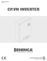
Selector Dial
(used for programming
and selecting wiring type) Main Motor Control Harness Connection
Maximum Run
Timer Button
Optional Auxiliary
Card Receptacles
Mid Stop Learn Button
Timer-To-Close
Learn Button
Radio Learn Button Open Button
Close Button
Stop Button
Control Wiring
Terminal Block
Motor Direction Jumper
Maintenance Alert
System Button for
Programming
Single Phase &
Three Phase Jumper
BASIC PROGRAMMING
LOGIC BOARD OVERVIEW
LOGIC BOARD PUSH BUTTONS (OPEN, CLOSE, STOP)
Open, Close and Stop buttons are mounted directly on the logic
board. Thus, making it easy to program as well as have door
control at the electrical box.
Either the stop control or a jumper MUST be wired between
terminals 4 and 5 for the on board push buttons to function.
NOTE: Before programming the logic board, set the operator’s
open and close limits. LEDs on the logic board are provided to
assist setting the limits. As each limit is activated the
corresponding LED will light up. The abbreviations are Open Limit
Switch (OLS), Close Limit Switch (CLS) and Sensing Limit Switch
(SLS). Refer to page 19 for limit switch adjustment instructions.
When power is applied to the operator, the following LED’s will
illuminate: STOP, CLOSE, OPEN, LMEP, 24Vac, RADIO, DATA,
TIMER ENABLE, OLS MID, SLS, CLS, and MAS. Once the power
up process is completed (approximately 2-3 seconds) only the
appropriate LED’s will continue to be lit (i.e., STOP, 24Vdc, limit
LED(s) if limit(s) is activated).
NOTE: When the power up process is over, the MAS LED will
blink a code indicating the version of firmware. If the selector dial
is in the DIAG, OPTN, or PROG position, the MAS will not provide
this code. After the code has been provided the MAS LED will go
out.
LOGIC BOARD LED OVERVIEW
Many programmable functions require that a LiftMaster Entrapment Protection (LMEP) device be installed in order to function.
Refer to the Entrapment Protection section.
2

DETERMINE AND SET WIRING TYPE
Read the descriptions of the different wiring types to determine which setting will be correct for each application. Once the wiring type
is determined, set the selector dial accordingly.
OPTN
PROG
DIAG
FSTS
TS
T
E2
D1
C2
B2
SELECTOR DIAL
IMPORTANT NOTES:
1. External interlocks may be used with all functional modes.
2. Auxiliary devices are any devices that have only dry contacts.
Examples: photocell, loop detector, pneumatic or electrical
treadles, radio controls, one button stations, pull cords, etc.
3. Open override means that the door may be reversed while
closing by activating an opening device without the need to use
the stop button first.
4. When the door is in a stopped position other than fully closed,
and a safety input is activated (LMEP or EDGE), the Restricted
Close (RC) feature will allow a close command when the close
button is pressed and held. The operator will begin closing after
5 seconds. If the close button is released the door will stop.
When in E2 mode, the door will move to the fully open position.
LIFTMASTER MONITORED ENTRAPMENT PROTECTION (LMEP)
DEVICE IS REQUIRED
A LiftMaster Entrapment Protection (LMEP) device is required for
the following wiring types.
LIFTMASTER MONITORED ENTRAPMENT PROTECTION (LMEP)
DEVICE IS RECOMMENDED
A LiftMaster Entrapment Protection (LMEP) device is
recommended for the following wiring types.
B2 Momentary contact to open, close and stop, plus wiring for
sensing device to reverse and auxiliary devices to open and
close with open override. Programmable mid stop available
with this wiring type. Compatible with 3-Button Station,
1-Button Station, 1 and 3-Button Remote Control.
TS (TIMER SECURE)
This mode will attempt to close the door from any position
except when fully closed, or when a safety input is present.
The stop button will not disable the Timer-To-Close at any
position. To disable the Timer-To-Close in this mode,
installation of a defeat switch is required (see wiring
diagram).
Momentary contact to open, close, and stop with open
override and Timer-To-Close. Every device that causes door
to open, including a reversing device, activates the Timer-
To-Close. Auxiliary controls can be connected to open input
to activate the Timer-To-Close. If the timer has been
activated, the open button and radio control can recycle the
timer. The Timer-To-Close will function from the
programmable mid stop with this wiring type. Compatible
with 3-Button Station, 1-Button Station and 1 and 3-Button
Remote Control.
NOTE: A Programmable “Car Dealer Mode” available.
T Momentary contact to open, close, and stop, with open
override and Timer-To-Close. Every device that causes the
door to open, except any safety edge input device, activates
the Timer-To-Close. Auxiliary controls can be connected to
open input to activate the Timer-To-Close. If the Timer-To-
Close has been activated, the open button and radio control
can recycle the timer. The stop button will deactivate the
timer until the next command input. The Timer-To-Close will
function from the programmable mid stop with this wiring
type. Compatible with 3-Button Station,1-Button Station
and 1 and 3-Button Remote Control.
NOTE: Programmable “Car Dealer Mode” available.
FSTS Momentary button contact for open, close and stop
programming. User set mid stop. User set Timer-To-Close.
The single button station opens the door to the full open
limit bypassing the mid stop and activates the Timer-To-
Close, putting the operator in TS mode until the door
reaches the down limit, or is stopped in travel. At which
time the operator enters the B2 mode.
Compatible with 3-Button Station, 1-Button Station, 1 and
3-Button Remote Control. A 1-Button remote control in
FSTS mode will open only with the Timer-To-Close,
bypassing a programmed mid stop. The Timer-To-Close will
reset and reverse when closing.
C2 Momentary contact to open and stop with constant pressure
to close, open override plus wiring for sensing device to
reverse. Programmable mid stop available with this wiring
type. Compatible with 3-Button Station and 1-Button
Station.
E2 Momentary contact to open with override and constant
pressure to close. Release of close button will cause door to
reverse (roll-back feature) plus wiring for sensing device to
reverse. Compatible with 3-Button Station.
D1 Constant pressure to open and close with wiring for sensing
device to stop. Compatible with 2 or 3-Button Station.
BASIC PROGRAMMING
3

RADIO
SLS
MRT MID TTC TIM
ENA
123
FSTS
TTS
E2
CLS
MID
MOTOR
DIRECTION
HASE
TTC
LMEP:
EDGE:
OPEN
CLOSE
STOP
COMMON
TIMER
ENABLE
3
FSTS
DIAG
OPTN
RADIO
SLS
MRT MID TTC TIM
ENA
123
FSTS
TTS
E2
CLS
MID
MOTOR
DIRECTION
ASE
REMOTE CONTROLS
To prevent possible SEVERE INJURY or DEATH:
• Install a LiftMaster Monitored Entrapment Protection (LMEP)
device.
• NEVER permit children to operate or play with door control
push buttons or remote controls.
• Activate door ONLY when it can be seen clearly, is properly
adjusted and there are no obstructions to door travel.
• ALWAYS keep door in sight until completely closed. NEVER
permit anyone to cross the path of closing door.
ATTENTION
AVERTISSEMENT AVERTISSEMENT
AVERTISSEMENT
WARNING WARNING
CAUTION
WARNING
WARNING
PRECAUCIÓN ADVERTENCIA
ADVERTENCIA ADVERTENCIA
BASIC PROGRAMMING
SINGLE BUTTON REMOTE CONTROL
3-BUTTON REMOTE CONTROL TO OPERATE AS A WIRELESS 3-BUTTON CONTROL STATION
NOTE: The feature will use 3 of the 23 memory channels in the operator.
TO ERASE ALL REMOTE CONTROLS
1Press and release the
RADIO button (RADIO
LED will light).
2
123
Press and release
the RADIO button
on the logic board
(the Radio LED
will light).
Press and release
the desired button
on the logic board
(OPEN, CLOSE or
STOP). The Radio
LED will fl ash and
then stay on solid.
Press and hold the desired button of the remote
control until Radio LED fl ashes rapidly, then
release.
Repeat steps 1 through 3 to program additional buttons.
Press and hold the remote control button until the
RADIO LED fl ashes rapidly, then release remote
control button. The RADIO LED will then remain
on solid after releasing the button. Repeat to add
additional remote control(s).
1Press and hold the
RADIO button on the
logic board until the
RADIO LED fl ashes
rapidly (approximately
5 seconds).
All remote controls
will be erased.
RADIO
SLS
MRT MID TTC TIM
ENA
123
FSTS
TTS
E2
CLS
MID
MOTOR
DIRECTION
ASE
3Press and release
the RADIO button
to complete the
programming. The
programming mode
is exited if no activity
is performed within
30 seconds.
RADIO
SLS
MRT MID TTC TIM
ENA
123
FSTS
TTS
E2
CLS
MID
MOTOR
DIRECTION
HASE
Built in 3-channel, 315 MHz radio receiver allows you to add as many as 23 Security✚® remotes or dip switch remote controls.
NOTE: The following programming requires a LiftMaster Monitored Entrapment Protection (LMEP) device.
4

BASIC PROGRAMMING
OPTN
PROG
DIAG
FSTS
TS
T
E2
D1
C2
B2
Operation will
vary depending
on wiring type
SELECTOR DIAL
OPTN
PROG
DIAG
FSTS
TS
T
E2
D1
C2
B2
To prevent possible SEVERE INJURY or DEATH:
• Install a LiftMaster Monitored Entrapment Protection (LMEP)
device.
• NEVER permit children to operate or play with door control
push buttons or remote controls.
• Activate door ONLY when it can be seen clearly, is properly
adjusted and there are no obstructions to door travel.
• ALWAYS keep door in sight until completely closed. NEVER
permit anyone to cross path of closing door.
ATTENTION
AVERTISSEMENT AVERTISSEMENT
AVERTISSEMENT
WARNING WARNING
CAUTION
WARNING
WARNING
PRECAUCIÓN ADVERTENCIA
ADVERTENCIA ADVERTENCIA
TIMER-TO-CLOSE
Feature: Timer automatically closes door after preset time. All
safety devices must be unobstructed.
Benefit: The door will automatically close after preset amount of
time. Great for apartment buildings, fire stations and other
applications where the end user wants the door to close
automatically after a specified amount of time.
Requirements: Must have at least one LiftMaster Monitored
Entrapment Protection (LMEP) device installed (refer to page 20).
Wiring type must be set to TS, T or FSTS.
TO PROGRAM MANUALLY (METHOD 1):
1. Close the door.
2. Turn the selector dial to PROGRAM.
3. Press and release the TIMER button on the logic board.
4. Press and release the STOP button to clear the timer.
5. Press and release the OPEN button for every second the
operator should wait before attempting to close the door. Press
and release the CLOSE button for every 15 seconds the
operator should wait before closing the door.
6. Press and release the TIMER button to complete programming.
The OPEN/CLOSE button LEDs will flash to confirm the timer
setting. The OPEN LED will flash once for every second
programmed and the CLOSE LED will flash once for every 15
seconds programmed.
7. Turn the selector dial to desired timer wiring type (TS ,T or
FSTS).
Example: To close the door after 70 seconds. Turn selector dial to
PROGRAM, press and release the TIMER button, press and
release the STOP button to clear the timer, press and release the
CLOSE button four times for 60 seconds and press and release
the OPEN button 10 times for 10 seconds. Press the TIMER
button to finish programming the timer. Turn selector dial to
desired timer wiring type. (TS, T, FSTS).
PROGRAM TIMER-TO-CLOSE BY EXAMPLE (Method 2):
TO PROGRAM:
1. Close the door.
2. Turn the selector dial to PROGRAM.
3. Press and hold TIMER button for 5 seconds until OPEN and
OLS flashes then release.
4. Press and release the OPEN button and wait for the door to
reach full open or mid stop position.
5. Wait for desired amount of time to pass. (An internal stop
watch starts counting when the door stops moving.)
6. Press and release the TIMER button, CLOSE button or STOP
button to stop the timer. (TIMER SET LED will turn on.)
7. Turn the selector dial to the desired wiring type (T, TS, FSTS).
NOTE: To read back the Timer-To-Close setting, turn the selector
dial to DIAGNOSTIC and press the TIMER button. The OPEN LED
will flash once for every second programmed and the CLOSE LED
will flash once for every 15 seconds programmed.
To deactivate the timer from the open position press the STOP
button. The timer will be reactivated on the next operation
command. To deactivate the timer for more than one cycle, attach
a switch to 11 and 12 (Common and Timer Defeat).
Reminders: FSTS wiring mode allows the Timer-To-Close to be
activated by the Single Button Control (terminal 1) only. T wiring
mode allows the door to attempt to close only one time for safety
purposes.
OPTN
PROG
DIAG
FSTS
TS
T
E2
D1
C2
B2
Operation will vary
depending on wiring type
SELECTOR DIAL
OPTN
PROG
DIAG
FSTS
TS
T
E2
D1
C2
B2
5

To prevent possible SERIOUS INJURY or DEATH from a falling
door or arm:
• DO NOT stand under the door arm when pulling the emergency
release.
• If possible, use emergency release handle to disengage trolley
ONLY when door is CLOSED. Weak or broken springs or
unbalanced door could result in an open door falling rapidly
and/or unexpectedly.
• NEVER use emergency release handle unless doorway is clear
of persons and obstructions.
EMERGENCY DISCONNECT SYSTEM MODEL GT AND T
MANUAL RELEASE
TO DISCONNECT DOOR FROM OPERATOR
The door should be in the fully closed position if possible.
Pull emergency release handle straight down. Emergency
disconnect will open.
TO RECONNECT DOOR ARM TO TROLLEY
Lift free end of door arm to trolley. Pull emergency release
handle to allow arm to engage roll pin. Release handle.
Emergency disconnect will close.
ATTENTION
AVERTISSEMENT AVERTISSEMENT
AVERTISSEMENT
WARNING
WARNING
CAUTION
WARNING
WARNING
PRECAUCIÓN ADVERTENCIA
ADVERTENCIA ADVERTENCIA
NO ECI
T
1
EMERGENCY DISCONNECT SYSTEM MODEL APT
TO DISCONNECT DOOR FROM OPERATOR
The door should be in the fully closed position if possible.
Pull down on the emergency release handle and raise or lower
the door manually.
TO RECONNECT DOOR ARM TO TROLLEY
The trolley will reconnect on the next UP or DOWN operation,
either manually or by using the door control or remote.
N O E C I
T
2
1
1
2
1
2
6

MANUAL RELEASE
This operator has provisions for manually operating the door
in case of emergency or power failure. Refer to the appropriate
instructions below for your model operator.
MODEL HJ
This operator includes both a fl oor level disconnect chain (sash
chain) to disconnect the door from the door operator and a
disconnect chain with manual hoist to electrically disable the
operator controls.
Pull the disconnect chain to engage the hoist mechanism.
The disconnect chain may be locked in position by slipping
the end through the keyhole of the chain keeper mounted on
the wall.
To disengage, pull the disconnect chain and secure in the
disengaged position by slipping the end through the keyhole
bracket mounted on the wall.
Operate the door in the desired direction by pulling on one
side or the other of the continuous loop hoist chain.
Release the disconnect chain to operate the door again
electrically.
To prevent possible SERIOUS INJURY from a moving chain:
• DISCONNECT electric power to the operator BEFORE manually
operating your door.
• If possible, use emergency disconnect ONLY when door is
CLOSED. Weak or broken springs or unbalanced door could
result in an open door falling rapidly and/or unexpectedly.
• NEVER use emergency disconnect unless doorway is clear of
persons and obstructions.
ATTENTION
AVERTISSEMENT AVERTISSEMENT
AVERTISSEMENT
WARNING
CAUTION
CAUTION
WARNING
WARNING
PRECAUCIÓN ADVERTENCIA
ADVERTENCIA ADVERTENCIA
1
3
4
These operators are equipped with a manual hoist. An electrical
interlock will disable the electrical controls when the hoist is used.
To operate the hoist:
Pull the disconnect chain (sash chain) to engage the hoist
mechanism. The disconnect chain may be locked in position
by slipping the end through the keyhole of the chain keeper
mounted on the wall.
Operate the door in the desired direction by pulling on one
side or the other of the continuous loop hoist chain.
The disconnect chain must be released from the chain keeper
before the door will operate again electrically.
MODEL H AND GH
3
1
2
MODEL J
This operator has a fl oor level disconnect chain to disconnect the
door from the door operator.
To disengage, pull the disconnect chain (sash chain) and
secure in the disengaged position by slipping the end
through the keyhole bracket mounted on the wall.
The door may now be pushed up or pulled down manually.
Release the disconnect chain to operate the door again
electrically.
1
2
2
3
1
3
2
H and GH
J
HJ
EMERGENCY DISCONNECT SYSTEM
MODEL H, GH, J, AND HJ
1
2
4
4
3
1
2
3
7

TESTING
8
TEST 3-BUTTON CONTROL STATION
1. Press OPEN button. (The door should move in the open
direction.)
2. Press STOP button. (The door should stop.)
3. Press and hold the CLOSE button. (The door should move in
the close direction.)
4. Release CLOSE button. Door should stop if in C2 or D1 mode.
Door will reverse to full open position in E2 mode. The door
should continue closing in all other modes.
5. Press STOP button. (The door should stop.)
TEST LIMIT ADJUSTMENT
1. Press OPEN button. (The door should open.)
2. Allow the door to fully open.
3. Press and hold the CLOSE button. (The door should close.)
4. Allow the door to fully close.
5. If the limits are not set properly, remove power and adjust
limits (refer to Limit Adjustment section).
TEST THE PHOTOELECTRIC SENSORS
1. Open the door.
2. Place an obstruction in the path of the photoelectric sensors.
The LMEP LED will blink on the logic board and the receiving
eye LED will turn off.
3. Press and hold the CLOSE button.
The door should not close if photoelectric sensors are
installed.
4. Remove the obstruction.
5. Press and hold the CLOSE button. Door should close.
If door did not reverse from obstruction, check
photoelectric sensors.
IMPORTANT NOTES:
• Do not leave power to the operator on unless all safety and
entrapment protection devices have been tested and are
working properly.
• Be sure you have read and understand all safety instructions
included in this manual.
• Be sure the owner or person(s) responsible for operation of the
door have read and understand the safety instructions, know
how to electrically operate the door in a safe manner and how
to manually disconnect the door from the operator.
To avoid SERIOUS personal INJURY or DEATH:
• Disconnect electric power BEFORE performing ANY
adjustments or maintenance.
• ALL maintenance MUST be performed by a trained door
systems technician.
ATTENTION
AVERTISSEMENT AVERTISSEMENT
AVERTISSEMENT
WARNING
CAUTION
WARNING
WARNING
WARNING
PRECAUCIÓN ADVERTENCIA
ADVERTENCIA ADVERTENCIA
Apply power to the operator.
When power is applied to the operator, the following LED’s will
illuminate: STOP, CLOSE, OPEN, LMEP, 24Vac, RADIO, DATA,
TIMER ENABLE, OLS MID, SLS, CLS, and MAS. Once the power
up process is completed (approximately 2-3 seconds) only the
appropriate LED’s will continue to be lit:
• Between limits: 24Vac and STOP
• Fully closed position: 24Vac, STOP, CLS and SLS
• Fully opened position: 24Vac, STOP and OLS
Additional LED’s will light when device(s) are activated.
NOTE: When the power up process is over, the MAS LED will
blink a code indicating the version of firmware. If the selector dial
is in the DIAG, OPTN, or PROG position, the MAS will not provide
this code. After the code has been provided the MAS LED will go
out.
1. After power is connected to the operator, the green indicator
lights in both the sending and receiving sensors will glow
steadily if wiring connections and alignment are correct.
2. If the receiving sensor indicator light is not glowing steadily
(and the invisible light beam path is not obstructed), alignment
is required:
• Loosen the receiving sensor wing nut to allow slight rotation of
the sensor. Adjust sensor vertically and/or horizontally until the
green indicator light glows steadily.
• When the indicator lights are glowing in both sensors, tighten
the receiving sensor wing nut.
ALIGN THE PHOTOELECTRIC SENSORS

To locate a dealer in your area visit us online at www.liftmaster.com
Every 3 months or 5,000 cycles repeat all tests in the Testing section.
Call a trained door systems technician. To locate a dealer in your area visit us online at www.liftmaster.com.
The operator should be serviced at the following intervals:
• Every 3 months or 5,000 cycles
• Every 6 months or 10,000 cycles
• Every 12 months or 20,000 cycles
TROUBLESHOOTING
MAINTENANCE SCHEDULE
To avoid SERIOUS personal INJURY or DEATH:
• Disconnect electric power BEFORE performing ANY
adjustments or maintenance.
• ALL maintenance MUST be performed by a trained door
systems technician.
ATTENTION
AVERTISSEMENT AVERTISSEMENT
AVERTISSEMENT
WARNING
CAUTION
WARNING
WARNING WARNING
PRECAUCIÓN ADVERTENCIA
ADVERTENCIA ADVERTENCIA
CONDITION POSSIBLE CAUSE FIX
OPERATOR WILL NOT
RESPOND TO ANY
COMMANDS
No power ➤ Check circuit breaker.
Accessory failure ➤ Verify photoelectric sensors are aligned.
Possible component failure ➤ Contact your installing dealer.
OPERATOR MAKES
NOISE BUT DOOR
DOES NOT MOVE
Operator requires adjustment ➤ Contact your installing dealer.
DOOR DRIFTS AFTER
OPERATOR STOPS
Operator or door requires
adjustment ➤ Contact your installing dealer.
DOOR OPENS/
CLOSES TOO FAR Operator requires adjustment ➤ Contact your installing dealer.
DOOR REVERSES
UNEXPECTEDLY
Entrapment protection device
activated
➤ Verify photoelectric sensors are aligned. If photoelectric sensors are
aligned and operator still does not operate properly, contact your
installing dealer.
RADIO FUNCTIONALITY
NO RESPONSE Remote control is not
programmed ➤ See PROGRAMMING REMOTE CONTROLS section.
Low battery ➤ Replace battery.
REMOTE CANNOT BE
PROGRAMMED Low battery ➤ Replace battery.
POOR RANGE Low battery in remote ➤ Replace battery.
Possible radio interference ➤ Contact your installing dealer.
9

OPERATOR NOTES
10

OPEN
OPEN
CLOSE
OPEN
OPEN
CLOSE
OPEN
OPENOPEN
CLOSECLOSE
OPEN
OPEN
CLOSE
OPEN
CLOSE
STOP
OPENOPEN
OPEN
CLOSE
OPEN
OPEN
CLOSE
OPEN
OPEN
CLOSE
373LM
371LM
65-8202
65-5202
3-Button SECURITY✚® Remote Control:
Includes visor clip.
1-Button SECURITY✚® Remote Control:
Includes visor clip.
Vehicle Detection System:
Pneumatic Sensing Edge Kit with exterior air switch, 2-wire
coil cord and 14' air hose.
Vehicle Detection System:
Pneumatic Sensing Edge Kit with exterior air switch, 2-wire
take-up reel (20' extended) and 14' air hose.
OPEN
OPEN
CLOSE
333LM 3-Button Tri-Colored Dip Switch Remote Control:
Includes visor clip.
2-Button Control Station:
Steel enclosure.
1-Button Control Station:
Steel enclosure.
Commercial Protector System®:
Provides protection on doors up to 45' wide. NEMA-4
rated.
CPS-UN4
3-Button Control Station:
Steel enclosure with Maintenance Alert System.
02-103L
OPEN
OPEN
CLOSE
Commercial Protector System®:
Provides protection on doors up to 30' wide.
CPS-U
OPEN
OPEN
CLOSE
OPEN
OPEN
CLOSE
ENTRAPMENT PROTECTION DEVICES
REMOTE CONTROLS 315MHz
CONTROL STATIONS
02-102
02-101
ACCESSORIES
CPS-EI Monitored Safety Edge Interface:
For use with the approved 4-wire safety edge (see below).
OPEN
OPEN
CLOSE
40-34141-1
LMEP2
LMEP1
E1
E2
E3
E4
CPS-EI
OPEN
OPEN
CLOSE
OPEN
STOP
CLOSE
Key Control Station:
Indoor flush mount, NEMA 1 with Stop button.
02-110
Timer Light Status Card:
The TLS option card provides special functionality to
activate and flash auxiliary devices such as lights, bells, and
horns/strobes at various door positions, and to provide
special timer functions.
TLSCARD
Auxiliary Contact Card:
The Auxiliary Contact option card has both Normally-Open
and Normally-Closed contacts that actuate when the door is
idle, opening, or closing.
AUXCARD
65ME1234 Miller ME123 4-Wire Monitored Safety Edge:
For sectional or rolling doors.
65ME123C U-Shaped Mounting Channel:
For 65ME1234 edge when installed on sectional doors.
65ME123C1 T-Shaped Mounting Channel:
For 65ME1234 edge when installed on rolling doors. Fits
between L-shaped angles used to construct a bottom bar
on rolling doors.
65ME123CA3 L-Shaped Mounting Channel:
For 65ME1234 edge when installed on sectional doors.
65ME110 Miller ME110 4-Wire Monitored Safety Edge:
For rolling grilles and counter shutters.
Cast iron bracket to mount J, H, DH, DJ, and GH side mount
operators on end bracket of a rolling door or grill. For
vertical or horizontal mount on either front or top of coil.
Heavy gauge steel bracket for vertical or horizontal mount
on either front or top of coil on a rolling door. Has a variety
of mounting hole patterns compatible with many OEM
manufacturers. May be welded. For use with J, H, DJ, and
DH operators.
08-9098
MOUNTING BRACKETS
OPEN
OPEN
CLOSE
OPEN
OPEN
CLOSE
10-12360
Same as 08-9098, but with adapter plate to hold mounting
bolt holes in place for ease of use.
Heavy gauge steel bracket for vertical or horizontal mount
on either front or top of coil on a rolling door. May be
welded. For use with J, H, DJ, and DH operators.
Same as 1A4324, but with adapter plate to hold mounting
bolt holes in place for ease of use.
08-9098EZ
1A4324
1A4324EZ
OPEN
OPEN
CLOSE
Operator Cover:
For use with wall-mounted J, H, GH, DH or DJ operators.
Measures 31" x 19" x 18" (L x W x D). Assembly required.
Recommended for damp environments where direct spray
is present. Required when the operator is installed less
than 8 feet above the floor.
1A3982
OPEN
OPEN
CLOSE
Antenna Extension Kit:
The antenna extension kit can be used with EXT-ANT for
maximum radio receiver range.
86LM (15')
86LMT (25')
MISCELLANEOUS
For 1" shafts. Recommended to properly tension drive chain
between operator shaft and door shaft.
71-6023
71-6125 Same as 71-6023, but for 1-1/4" shafts.
For Jackshaft Type Operators
CHAIN TENSIONERS
MOUNTING CHANNELS
CPS3 Option Logic Board:
For use when more than one set of photoelectric eyes are
required.
MONITORED
NON-MONITORED
OPEN
OPEN
CLOSE
11

© 2010, The Chamberlain Group, Inc.
01-35242 All Rights Reserved
/