Schneider Electric ATV212 Installation guide

Type
Installation guide
S1A53832.05
www.schneider-electric.com
A
ltivar Proces s
S1A53832 06/202306/2023
Altivar 212
Variable speed drives
for synchronous and asynchronous motors
Installation manual
06/2023
2S1A53832 06/202306/2023
The information provided in this documentation contains general descriptions and/or technical character-
istics of the performance of the products contained herein. This documentation is not intended as a
substitute for and is not to be used for determining suitability or reliability of these products for specific user
applications. It is the duty of any such user or integrator to perform the appropriate and complete risk
analysis, evaluation and testing of the products with respect to the relevant specific application or use
thereof. Neither Schneider Electric nor any of its affiliates or subsidiaries shall be responsible or liable for
misuse of the information contained herein. If you have any suggestions for improvements or amendments
or have found errors in this publication, please notify us.
You agree not to reproduce, other than for your own personal, noncommercial use, all or part of this
document on any medium whatsoever without permission of Schneider Electric, given in writing. You also
agree not to establish any hypertext links to this document or its content. Schneider Electric does not grant
any right or license for the personal and noncommercial use of the document or its content, except for a
non-exclusive license to consult it on an "as is" basis, at your own risk. All other rights are reserved.
All pertinent state, regional, and local safety regulations must be observed when installing and using this
product. For reasons of safety and to help ensure compliance with documented system data, only the
manufacturer should perform repairs to components.
When devices are used for applications with technical safety requirements, the relevant instructions must
be followed.
Failure to use Schneider Electric software or approved software with our hardware products may result in
injury, harm, or improper operating results.
Failure to observe this information can result in injury or equipment damage.
© 2023 Schneider Electric. All rights reserved.
3
Table of Contents
Safety Information .......................................................................................... 5
About the Book ............................................................................................... 9
Device overview ......................................................................................................................... 14
Reference description ................................................................................................................ 15
Green Premium™ ...................................................................................................................... 15
Chapter 1 Before You Begin ........................................................................................... 17
Lifting and handling instructions ................................................................................................. 18
Chapter 2 Steps for Setting Up ....................................................................................... 19
Steps for setting up .................................................................................................................... 20
Chapter 3 Upstream Protective Device ........................................................................... 21
Prospective Short-Circuit Current .............................................................................................. 24
IEC Fuses - With enclosure ....................................................................................................... 26
IEC Fuses - Wall mounted ......................................................................................................... 29
UL Circuit-Breakers and Fuses .................................................................................................. 32
Chapter 4 Technical Data ............................................................................................... 33
ATV212H dimensions and weights ............................................................................................ 34
ATV212W dimensions and weights ........................................................................................... 36
Electrical data ............................................................................................................................ 37
Connection diagrams ................................................................................................................. 39
Examples of recommended circuit diagrams ............................................................................. 40
Chapter 5 Installation ...................................................................................................... 41
Drive mounting generalities ....................................................................................................... 42
Specific recommendations for mounting in an enclosure .......................................................... 51
Position of the charging LED ..................................................................................................... 52
Opening the drive to access terminals ....................................................................................... 52
Wiring recommendations ........................................................................................................... 55
Power terminals ......................................................................................................................... 57
Control terminals and switches .................................................................................................. 62
Installing option card .................................................................................................................. 65
Use on an impedance grounded (IT) system ............................................................................. 66
Electromagnetic compatibility (EMC) ......................................................................................... 69
Checking the Installation ............................................................................................................ 73
Recommended branch circuit protection devices ...................................................................... 74
Chapter 6 Maintenance ................................................................................................... 75
Scheduled Servicing .................................................................................................................. 76
Long-term Storage ..................................................................................................................... 77
Decommissioning ....................................................................................................................... 77
Additional Support ...................................................................................................................... 77
Chapter 7 Migration ATV21 --> ATV212 ......................................................................... 79
Generalities ................................................................................................................................ 80
Differentiating points .................................................................................................................. 80
Terminal and switches arrangement comparison ...................................................................... 81
4
S1A53832 03/2019 5
Safety Information
Important Information
S1A53832 03/2019
NOTICE
Read these instructions carefully, and look at the equipment to become familiar with the device before
trying to install, operate, service, or maintain it. The following special messages may appear throughout
this documentation or on the equipment to warn of potential hazards or to call attention to information that
clarifies or simplifies a procedure.
PLEASE NOTE
Electrical equipment should be installed, operated, serviced, and maintained only by qualified personnel.
No responsibility is assumed by Schneider Electric for any consequences arising out of the use of this
material.
A qualified person is one who has skills and knowledge related to the construction and operation of
electrical equipment and its installation, and has received safety training to recognize and avoid the
hazards involved.
Qualification Of Personnel
Only appropriately trained persons who are familiar with and understand the contents of this manual and
all other pertinent product documentation are authorized to work on and with this product. In addition, these
persons must have received safety training to recognize and avoid hazards involved. These persons must
have sufficient technical training, knowledge and experience and be able to foresee and detect potential
hazards that may be caused by using the product, by changing the settings and by the mechanical,
electrical and electronic equipment of the entire system in which the product is used. All persons working
on and with the product must be fully familiar with all applicable standards, directives, and accident
prevention regulations when performing such work.
6S1A53832 03/2019
Intended Use
This product is a drive for three-phase synchronous, asynchronous motors and intended for industrial use
according to this manual. The product may only be used in compliance with all applicable safety standard
and local regulations and directives, the specified requirements and the technical data. The product must
be installed outside the hazardous ATEX zone. Prior to using the product, you must perform a risk
assessment in view of the planned application. Based on the results, the appropriate safety measures must
be implemented. Since the product is used as a component in an entire system, you must ensure the safety
of persons by means of the design of this entire system (for example, machine design). Any use other than
the use explicitly permitted is prohibited and can result in hazards.
Product Related Information
Read and understand these instructions before performing any procedure with this drive.
Damaged products or accessories may cause electric shock or unanticipated equipment operation.
Contact your local Schneider Electric sales office if you detect any damage whatsoever.
DANGER
HAZARD OF ELECTRIC SHOCK, EXPLOSION OR ARC FLASH
Only appropriately trained persons who are familiar with and understand the contents of this manual
and all other pertinent product documentation and who have received safety training to recognize and
avoid hazards involved are authorized to work on and with this drive system. Installation, adjustment,
repair and maintenance must be performed by qualified personnel.
The system integrator is responsible for compliance with all local and national electrical code
requirements as well as all other applicable regulations with respect to grounding of all equipment.
Many components of the product, including the printed circuit boards, operate with mains voltage.
Only use properly rated, electrically insulated tools and measuring equipment.
Do not touch unshielded components or terminals with voltage present.
Motors can generate voltage when the shaft is rotated. Prior to performing any type of work on the
drive system, block the motor shaft to prevent rotation.
AC voltage can couple voltage to unused conductors in the motor cable. Insulate both ends of unused
conductors of the motor cable.
Do not short across the DC bus terminals or the DC bus capacitors or the braking resistor terminals.
Before performing work on the drive system:
Disconnect all power, including external control power that may be present. Take into account that
the circuit breaker or main switch does not de-energize all circuits.
Place a Do Not Turn On label on all power switches related to the drive system.
Lock all power switches in the open position.
Wait 15 minutes to allow the DC bus capacitors to discharge.
Measure the voltage on the DC bus between the DC bus terminals (PA/+ and PC/-) using a properly
rated voltmeter to verify that the voltage is <42 Vdc.
If the DC bus capacitors do not discharge properly, contact your local Schneider Electric represen-
tative. Do not repair or operate the product.
Install and close all covers before applying voltage.
Failure to follow these instructions will result in death or serious injury.
DANGER
ELECTRIC SHOCK OR UNANTICIPATED EQUIPMENT OPERATION
Do not use damaged products or accessories.
Failure to follow these instructions will result in death or serious injury.
S1A53832 03/2019 7
This equipment has been designed to operate outside of any hazardous location. Only install this
equipment in zones known to be free of a hazardous atmosphere.
Drive systems may perform unexpected movements because of incorrect wiring, incorrect settings,
incorrect data or other errors.
(1) For USA: Additional information, refer to NEMA ICS 1.1 (latest edition), Safety Guidelines for the
Application, Installation, and Maintenance of Solid State Control and to NEMA ICS 7.1 (latest edition),
Safety Standards for Construction and Guide for Selection, Installation and Operation of Adjustable-Speed
Drive Systems.
The temperature of the products described in this manual may exceed 80 °C (176 °F) during operation.
DANGER
POTENTIAL FOR EXPLOSION
Install and use this equipment in non-hazardous locations only.
Failure to follow these instructions will result in death or serious injury.
WARNING
UNANTICIPATED EQUIPMENT OPERATION
Carefully install the wiring in accordance with the EMC requirements.
Do not operate the product with unknown or unsuitable settings or data.
Perform a comprehensive commissioning test.
Failure to follow these instructions can result in death, serious injury, or equipment damage.
WARNING
LOSS OF CONTROL
The designer of any control scheme must consider the potential failure modes of control paths and,
for critical control functions, provide a means to achieve a safe state during and after a path failure.
Examples of critical control functions are emergency stop, overtravel stop, power outage and restart.
Separate or redundant control paths must be provided for critical control functions.
System control paths may include communication links. Consideration must be given to the
implications of unanticipated transmission delays or failures of the link.
Observe all accident prevention regulations and local safety guidelines (1).
Each implementation of the product must be individually and thoroughly tested for proper operation
before being placed into service.
Failure to follow these instructions can result in death, serious injury, or equipment damage.
WARNING
HOT SURFACES
Ensure that any contact with hot surfaces is avoided.
Do not allow flammable or heat-sensitive parts in the immediate vicinity of hot surfaces.
Verify that the product has sufficiently cooled down before handling it.
Verify that the heat dissipation is sufficient by performing a test run under maximum load conditions.
Failure to follow these instructions can result in death, serious injury, or equipment damage.
NOTICE
DESTRUCTION DUE TO INCORRECT MAINS VOLTAGE
Before switching on and configuring the product, verify that it is approved for the mains voltage.
Failure to follow these instructions can result in equipment damage.
8S1A53832 03/2019
S1A53832 03/2019 9
About the Book
At a Glance
S1A53832 03/2019
Document Scope
The purpose of this document is:
to give you mechanical and electrical information related to the Altivar 212 drive,
to show you how to install and wire this drive.
Validity Note
Original instructions and information given in the present document have been written in English (before
optional translation).
NOTE: The products listed in the document are not all available at the time of publication of this document
online. The data, illustrations and product specifications listed in the guide will be completed and updated
as the product availabilities evolve. Updates to the guide will be available for download once products are
released on the market.
This documentation is valid for the Altivar 212 drive.
The technical characteristics of the devices described in the present document also appear online. To
access the information online:
The characteristics that are presented in the present document should be the same as those character-
istics that appear online. In line with our policy of constant improvement, we may revise content over time
to improve clarity and accuracy. If you see a difference between the document and online information, use
the online information as your reference.
Related Documents
Use your tablet or your PC to quickly access detailed and comprehensive information on all our products
on www.schneider-electric.com.
The internet site provides the information you need for products and solutions:
The whole catalog for detailed characteristics and selection guides,
The CAD files to help design your installation, available in over 20 different file formats,
All software and firmware to maintain your installation up to date,
A large quantity of White Papers, Environment documents, Application solutions, Specifications... to
gain a better understanding of our electrical systems and equipment or automation,
Step Action
1 Go to the Schneider Electric home page
www.se.com
.
2 In the Search box type the reference of a product or the name of a product range.
Do not include blank spaces in the reference or product range.
To get information on grouping similar modules, use asterisks (
*
).
3 If you entered a reference, go to the Product Datasheets search results and click on the reference that
interests you.
If you entered the name of a product range, go to the Product Ranges search results and click on the
product range that interests you.
4 If more than one reference appears in the Products search results, click on the reference that interests
you.
5 Depending on the size of your screen, you may need to scroll down to see the data sheet.
6 To save or print a data sheet as a .pdf file, click Download XXX product datasheet.
10 S1A53832 03/2019
And finally all the User Guides related to your drive, listed below:
You can download these technical publications and other technical information from our website at
www.se.com/en/download
Electronic Product Data sheet
Scan the QR code in front of the drive to get the product data sheet.
Terminology
The technical terms, terminology, and the corresponding descriptions in this manual normally use the
terms or definitions in the relevant standards.
In the area of drive systems this includes, but is not limited to, terms such as error, error message, failure,
fault, fault reset, protection, safe state, safety function, warning, warning message, and so on.
Among others, these standards include:
IEC 61800 series: Adjustable speed electrical power drive systems
IEC 61508 Ed.2 series: Functional safety of electrical/electronic/programmable electronic safety-related
EN 954-1 Safety of machinery - Safety related parts of control systems
ISO 13849-1 & 2 Safety of machinery - Safety related parts of control systems
IEC 61158 series: Industrial communication networks - Fieldbus specifications
IEC 61784 series: Industrial communication networks - Profiles
IEC 60204-1: Safety of machinery - Electrical equipment of machines – Part 1: General requirements
In addition, the term zone of operation is used in conjunction with the description of specific hazards, and
is defined as it is for a hazard zone or danger zone in the EC Machinery Directive (2006/42/EC) and in ISO
12100-1.
Also see the glossary at the end of this manual.
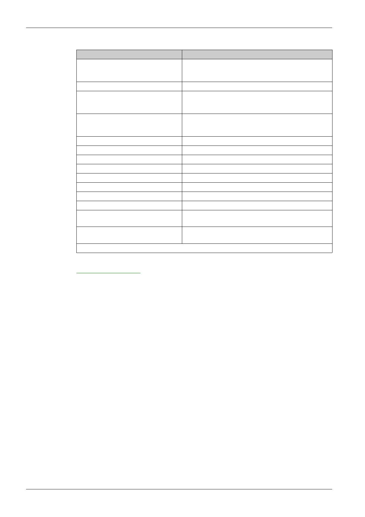
Title of Documentation Catalog Number
ATV212 Quick Start guide
S1A53825 (English), S1A53826 (French), S1A53827
(German), S1A53828 (Spanish), S1A53830 (Italian),
S1A53831 (Chinese)
ATV212 Quick Start guide - Annex S1A73476 (English)
ATV212 Installation manual
S1A53832 (English), S1A53833 (French), S1A53834
(German), S1A53836 (Spanish), S1A53835 (Italian),
SCDOC1563 (Chinese)
ATV212 Programming manual
S1A53838 (English), S1A53839 (French), S1A53840
(German), S1A53842 (Spanish), S1A53841 (Italian),
SCDOC1564 (Chinese)
ATV212 Catalog DIA2ED2101102EN (English)
ATV212 Modbus manual S1A53844 (English)
ATV32 Profinet manual HRB25668 (English)
ATV212 BACnet manual S1A53845 (English)
ATV212 Metasys N2 manual S1A53846 (English)
ATV212 Apogee FLN P1 manual S1A53847 (English)
ATV212 LONWORKS manual S1A53848 (English)
Multiloader manual BBV48778 (English)
SoMove: FDT SoMove_FDT (English, French, German, Spanish, Italian,
Chinese)
Altivar DTM Altivar_DTM_Library (English, French, German, Spanish,
Italian, Chinese)
ATV212 other option manuals: see www.se.com
S1A53832 03/2019 11
Contact Us
Select your country on:
www.se.com/contact
Schneider Electric Industries SAS
Head Office
35, rue Joseph Monier
92500 Rueil-Malmaison
France
12 S1A53832 03/2019
S1A53832 06/2023 13
ltivar Process
S1A53832 06/2023
Chapter 1
Introduction
What's in this Chapter?
This chapter contains the following topics:
Topic Page
Device overview 14
Reference description 15
Green Premium™ 15
14 S1A53832 06/2023
Device overview
The product
The ATV212 drive is mainly dedicated to HVAC applications in Building sector. The ATV212 drive family consists
of five IP21 and two IP55 product sizes
The IP21 «H» range - 5 drive sizes - Three-phase 50/60 Hz supply voltage
The IP55 «W» range - 2 drive sizes - Three-phase 50/60 Hz supply voltage
ATV212H075M3X, U15M3X, U22M3X,
075N4, U15N4, U22N4, U30M3X,
U40M3X, U30N4, U40N4, U55N4
ATV212HU55M3X, U75M3X, U75N4,
D11N4
ATV212HD11M3X, D15M3X, D15N4,
D18M3X, D18N4, D22N4S
0.75 to 5.5 kW 5.5 to 11 kW 11 to 22 kW
ATV212HD22M3X, D22N4, D30N4,
D37N4, D45N4 ATV212HD30M3X, D55N4, D75N4
22 to 45 kW 30 to 75 kW
ATV212W075N4…U22N4,
U30N4...U75N4 ATV212WD11N4...D75N4
0.75 to 7.5 kW 11 to 75 kW
S1A53832 06/2023 15
Reference description
IP21 and IP55 variable speed drives - Three-phase 50/60 Hz supply voltage: 200 ... 240 V and 380 ... 480 V
Green Premium™
Description
Information on the environmental impact of products, their resource efficiency, and end-of-life instructions.
Easy access to information: "Check Your Product"
Certificates and relevant product information available at the address:
www.se.com/green-premium
You can download RoHS and REACh compliance declarations, Product Environmental Profiles (PEP) and End-
of-Life instructions (EoLi).
ATV 212 HD30 N4 S
Product designation ATV - Altivar
Product range
Degree of protection
H - IP21 product
W - IP55 product
Drive rating
075 - 0.75 kW (1 HP)
U15 - 1.5 kW (2 HP)
U22 - 2.2 kW (3 HP)
U30 - 3 kW
U40 - 4 kW (5 HP)
U55 - 5.5 kW (71/2 HP)
U75 - 7.5 kW (10 HP)
D11 - 11 kW (15 HP)
D15 - 15 kW (20 HP)
D18 - 18.5 kW (25 HP)
D22 - 22 kW (30 HP)
D30 - 30 kW (40 HP)
D37 - 37 kW (50 HP)
D45 - 45 kW (60 HP)
D55 - 55 kW (75 HP)
D75 - 75 kW (100 HP)
380 - 480 V range only
Power supply voltage
M3X: 200 - 240 V range three-phase
N4: 380 - 480 V range three-phase (With integrated EMC filter C2, C3)
N4C: 380 - 480 V range three-phase (With integrated C1 EMC filter for UL Type 12/IP55 products ATV212Wpppppp)
Slim version
N4S: Available for 22 kW (30 HP) rating, IP21 version
16 S1A53832 06/2023
S1A53832 06/2023 17
ltivar Process
S1A53832 06/2023
Chapter 2
Before You Begin
What's in this Chapter?
/2018What's in this Chapte r?
This chapter contains the following topics:
Topic Page
Lifting and handling instructions 18
18 S1A53832 03/2019
Lifting and handling instructions
Storing and shipping
If the drive is not immediately installed, store it in a clean, dry area where the ambient temperature is between
–25 and +70 °C (–13 to +158 °F). If the drive has to be shipped to another location, use the original shipping
material and carton to help protect the drive.
WARNING
HANDLING AND LIFTING HAZARD
Keep the area below any equipment being lifted clear of all personnel and property. Use the lifting method
illustrated in following figure.
Failure to follow these instructions can result in death, serious injury, or equipment damage.
Altivar 212 drives up to
ATV212HD22N4S and
ATV212W075N4 can be removed
from their packaging and installed
without a handling device.
A hoist must be used for higher
ratings.
After removing the drive from its
packaging, inspect it for damage. If
any damage is found, notify the carrier
and your sales representative.
Verify that the drive nameplate and
label conform to the packing slip and
corresponding purchase order.
45°
max.
Spreader
bar
YN
Lifting
force
Lifting
force
WARNING
RISK OF TOPPLING
Keep the drive on the pallet until ready to install.
Never place the drive in an upright position without proper support, such as a hoist, braces, or other
mounting supports.
Failure to follow these instructions can result in death, serious injury, or equipment damage.
NOTICE
RISK OF DERATED PERFORMANCE DUE TO CAPACITOR AGING
The product capacitor performances after a long time storage above 2 years can be degraded.
In that case, before using the product , apply the following procedure:
Use a variable AC supply connected between L1 and L2 (even for ATV212pppN4 references).
Increase AC supply voltage to have:
- 80% of rated voltage during 30 min
- 100% of rated voltage for another 30 min
Failure to follow these instructions can result in equipment damage.
S1A53832 06/2023 19
ltivar Process
S1A53832 06/2023
Chapter 3
Steps for Setting Up
What's in this Chapter?
This chapter contains the following topics:
Topic Page
Steps for setting up 20
20 S1A53832 06/2023
Steps for setting up
1. Check the delivery of the drive
vCheck that the part number printed on the label is the same as that on the
purchase order.
vRemove the Altivar from its packaging and check that it has not been damaged
in transit.
2. Check the line voltage compatibility
vCheck that the voltage range of the drive is compatible with the
supply voltage (see page 37).
3. Mount the drive vertically
vMount the drive in accordance with the instructions in
this document (see page 42).
vInstall any options required
(see option documentation).
4. Wire the drive (see page 55)
vConnect the line supply and the ground, after
making sure that the power is off.
vConnect the motor, ensuring that its
connections correspond to the voltage.
vConnect the control part.
5. Please refer to the
programming manual.
PROGRAMMING
INSTALLATION
Steps 1 to 4 must be
performed with the power off.
  • Page 1 1
  • Page 2 2
  • Page 3 3
  • Page 4 4
  • Page 5 5
  • Page 6 6
  • Page 7 7
  • Page 8 8
  • Page 9 9
  • Page 10 10
  • Page 11 11
  • Page 12 12
  • Page 13 13
  • Page 14 14
  • Page 15 15
  • Page 16 16
  • Page 17 17
  • Page 18 18
  • Page 19 19
  • Page 20 20
  • Page 21 21
  • Page 22 22
  • Page 23 23
  • Page 24 24
  • Page 25 25
  • Page 26 26
  • Page 27 27
  • Page 28 28
  • Page 29 29
  • Page 30 30
  • Page 31 31
  • Page 32 32
  • Page 33 33
  • Page 34 34
  • Page 35 35
  • Page 36 36
  • Page 37 37
  • Page 38 38
  • Page 39 39
  • Page 40 40
  • Page 41 41
  • Page 42 42
  • Page 43 43
  • Page 44 44
  • Page 45 45
  • Page 46 46
  • Page 47 47
  • Page 48 48
  • Page 49 49
  • Page 50 50
  • Page 51 51
  • Page 52 52
  • Page 53 53
  • Page 54 54
  • Page 55 55
  • Page 56 56
  • Page 57 57
  • Page 58 58
  • Page 59 59
  • Page 60 60
  • Page 61 61
  • Page 62 62
  • Page 63 63
  • Page 64 64
  • Page 65 65
  • Page 66 66
  • Page 67 67
  • Page 68 68
  • Page 69 69
  • Page 70 70
  • Page 71 71
  • Page 72 72
  • Page 73 73
  • Page 74 74
  • Page 75 75
  • Page 76 76
  • Page 77 77
  • Page 78 78
  • Page 79 79
  • Page 80 80
  • Page 81 81
  • Page 82 82
  • Page 83 83

Schneider Electric ATV212 Installation guide

Type
Installation guide

Ask a question and I''ll find the answer in the document

Finding information in a document is now easier with AI