Page is loading ...

INSTRUCTIONS FOR INSTALLATION, OPERATION AND
MAINTENANCE
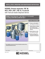
KESSEL Grease separator EasyClean free
Mix, Auto Mix, Mix & Pump, Auto Mix & Pump - oval
in NS 2, 4, 7, 10, 15, 20, 25, 30, 35, 40, 50 and 60
for set-up in frost-free rooms
As at 2023/06 Code no. 016-527_EN
Installation Putting into operation Instructional brieng
for the system was carried out by your specialist company:
Name/signature Date Town/City
in accordance with DIN 4040
in accordance with Euro
standard EN 1825
100% resistant to aggressive
fatty acids
Easy operation
Upgrading to all
variants possible
20 year guarantee
for tanks
Product advantages
Stamp of specialist company
Subject to technical modications
GB Page 1- 63

2 / 63
Table of Contents
2023/06016-527_EN
1 Introduction 4
1.1 Product description, general ............................................................................................. 4
1.2 Use.................................................................................................................................... 4
1.3 System types .................................................................................................................... 5
1.4 Overview of article numbers ............................................................................................. 5
1.5 Type plate ......................................................................................................................... 6
1.6 Scope of delivery .............................................................................................................. 7
1.7 General information on these operating and maintenance instructions ............................ 7
1.8 Assemblies and functional characteristics ........................................................................ 8
1.9 Illustrations and dimensions ............................................................................................. 9
1.9.1 Illustration system types - C .............................................................................................. 10
1.9.2 Illustration system types - D .............................................................................................. 11
1.9.3 Illustration system types - E .............................................................................................. 12
1.9.4 Illustration system types - F .............................................................................................. 13
1.9.5 Control unit ....................................................................................................................... 14
2 Safety 16
2.1 Intended use ..................................................................................................................... 16
2.2 Personnelselectionandqualication ............................................................................... 16
2.3 Organisational safety measures ....................................................................................... 16
2.4 Hazards caused by the product ........................................................................................ 17
2.4.1 Risk caused by electric current and cables ...................................................................... 17
2.4.2 Risk caused by heat development at the pump(s) ............................................................ 17
2.4.3 Danger of slipping when the system is emptied ............................................................... 17
2.4.4 Risk of infection when coming into contact with the wastewater ...................................... 17
3 Installation 18
3.1 Recommendations for the set-up location / operation ...................................................... 18
3.2 Setting up / installing the grease separator system .......................................................... 18
3.2.1 Fitting the inlet and outlet .................................................................................................. 19
3.2.2 Fitting or removing the pump ............................................................................................ 19
3.2.3 Mountingtherellinlet ...................................................................................................... 20
3.2.4 Installing the screw-type valve - E .................................................................................... 20
3.2.5 Installing the solenoid valves - F ....................................................................................... 20
3.2.6 Installing the SonicControl sensor (option) - F .................................................................. 21
3.2.7 Mounting the remote control - F ........................................................................................ 22
3.3 Mounting and initialising the control unit .......................................................................... 22
3.3.1 Control unit for system type D .......................................................................................... 22
3.3.2 Control unit for system type E ........................................................................................... 26
3.3.3 Control unit for system type F ........................................................................................... 28
1 Table of Contents

Table of Contents
3 / 632023/06 016-527_EN
3.4 Initialllingandpressuretest ........................................................................................... 32
3.4.1 Function check system type C .......................................................................................... 32
3.4.2 Function check system type D .......................................................................................... 33
3.4.3 Function check system type E .......................................................................................... 34
3.4.4 Function check system type F .......................................................................................... 34
4 Operation 36
4.1 Switching on system type C .............................................................................................. 36
4.2 Switching on system type D .............................................................................................. 36
4.3 Switching on system type E .............................................................................................. 37
4.4 Switching on system type F .............................................................................................. 37
5 Carrying out emptying 38
5.1 Emptying system type C ................................................................................................... 39
5.2 Emptying system type D ................................................................................................... 40
5.3 Emptying system type E ................................................................................................... 41
5.4 Emptying system type F ................................................................................................... 43
6 Settings, operating menu 47
6.1 System type D .................................................................................................................. 47
6.2 System type E ................................................................................................................... 49
6.3 System type F ................................................................................................................... 49
7 Technical data 54
7.1 Pre-conditions / basis for calculation ................................................................................ 54
7.2 General technical data / connected values ....................................................................... 54
7.3 Torques ............................................................................................................................. 55
7.4 Connections ...................................................................................................................... 55
8 Maintenance 56
8.1 Maintenance intervals ....................................................................................................... 56
8.2 Carrying out the maintenance of SonicControl (optional) ................................................. 56
8.3 Repairs if the pump is faulty ............................................................................................. 56
8.4 Troubleshooting ................................................................................................................ 57
8.5 Clean the grease separator .............................................................................................. 59
9 System passport / factory approval 60
10 General inspection / maintenance requirements 61
11 Declaration of Performance 62
12 Declaration of Conformity 63

4 / 63
Introduction
2023/06016-527_EN
1 Introduction
Dear Customer,
We are pleased that you have decided to buy one of our products. We are certain that it will fully meet your
requirements.
These installation, operating and maintenance instructions contain important information that has to be observed
during installation, assembly, operation, maintenance and repair. Prior to carrying out any work on the system, the
operatorandtheresponsiblespecialiststamustcarefullyreadandheedtheseinstructions.Wewishyousmooth
and successful installation.
In trying to keep our quality standard as high as possible, we rely on your help of course. Please let us know of
any possible improvements we could make to our product.
Do you have any questions? We look forward to hearing from you.
1.1 Product description, general
The grease separator separates greases, oils and sludge out of the wastewater. The grease separator system
hasbeendesignedinaccordancewithEN1825.Thewastecanbeextractedoatanytimeandwithout
interrupting operation. Depending on the model type, the grease separator system is equipped with an electric
system control and pump as well as various control valves. A viewing window makes it possible to check the
amount of grease collected in the system tank.
1.2 Use
Animal and vegetable oils and fats must not be discharged into public disposal systems and into bodies of water,
since they can cause narrowing of cross-sections and blockages in the disposal pipes when they set. In addition,
fatty acids are produced after a short decomposing time, leading to unpleasant odours and corroding pipes and
constructionalelementsofthedrainingsystems.Thesolidiedgreaselayeronthesurfaceofthewateralso
hinders the necessary oxygen supply to bodies of water and sewage treatment plants.
DIN 1986 Part 1 requires harmful substances to be trapped. For these reasons, grease separator systems
according to DIN 4040 or prEN 1825 must be planned, and disposal must take place accordingly.

Introduction
5 / 632023/06 016-527_EN
1.3 System types
The grease separator system is made in these versions:
System type
(code for installation)
System designation
Control unit type
Direct disposal pipe
Rellinlet
Inspection window
RemoteControl**
2 solenoid valves
Two-way valve, manual
Two-way valve, electric
C Grease separator Mix - oval -x x x*
D Grease separator Auto Mix - oval “Auto Mix” x x x x* x
E Grease separator Mix & Pump- oval “Mix & Pump” x x x x* x
F Grease separator Auto Mix & Pump- oval “Auto Mix & Pump” x x x x* x x
* Optional
** Wired remote control
1.4 Overview of article numbers
Nominal size C D E F
2 93002.04/DS 93002.04/MS 93002.04/DSP 93002.04/PVS
4 93004.04/DS 93004.04/MS 93004.04/DSP 93004.04/PVS
7 93007.04/DS 93007.04/MS 93007.04/DSP 93007.04/PVS
10 93010.04/DS 93010.04/MS 93010.04/DSP 93010.04/PVS
15 93015.01/DS 93015.01/MS 93015.01/DSP 93015.01/PVS
20 93020.01/DS 93020.01/MS 93020.01/DSP 93020.01/PVS
25 93025.01/DS 93025.01/MS 93025.01/DSP 93025.01/PVS
30 93030.01/DS 93030.01/MS 93030.01/DSP 93030.01/PVS
35 93035.01/DS 93035.01/DSP 93035.01/MS 93035.01/PVS
40 93040.01/DS 93040.01/DSP 93040.01/MS 93040.01/PVS
50 93050.01/DS 93050.01/DSP 93050.01/MS 93050.01/PVS
60 93060.01/DS 93060.01/DSP 93060.01/MS 93060.01/PVS
C D E F

6 / 63
Introduction
2023/06016-527_EN
1.5 Type plate
Information on the type plate of the grease separator system
10 Serial number
52 Material description
53 Material number
55 Standard
56 Free text / explanation
57 Free text / explanation
58 Free text / explanation
59 Free text / explanation
75 Free text / explanation
76 Material
77 Approval
78 Gross weight
79 Date of manufacture
80 Order number
Information on the type plate of the control unit
1 Name of the control unit
2 Material number of the control unit
3 Connection voltage and connection frequency
4 Current consumption range
5 Protective rating (IP)
6 Serial number of the control unit
7 Spare part number of the control unit
8 Danger sign (electr. control unit)
9 Protective class I - protective earth
10 CE marking
11 Hazardous waste electric device - emptying not via
domestic waste
12 Hardware revision status
Bahnhofstraße 31
D-85101 Lenting
Made in Germany
79
78
80
77
76
75
59
52
53
10
55
56
57
58
Fig. [1]
FA PV 400
IP 54
363-232 (363-412)
SerNr. XXXX
Ue: 400 VAC - 50 Hz
Ie: 6,3 - 10,0 A
Bahnhofstraße 31
D-85101 Lenting
RevStd. X.X
SachNr. 363-310
2
1
2
3
4
5
612
10
11
8
7
9
Fig. [2]

Introduction
7 / 632023/06 016-527_EN
1.6 Scope of delivery
– Grease separator syst(see 1.8 Assemblies and functional characteristics on page 8)
– Operating and maintenance instructions
– Solenoid valves (except for system type C - “Mix” variant)
1.7 General information on these operating and maintenance instructions
Symbols and keys used
<1> Reference in the text to a key number in an illustration
[2] Reference to an illustration (Figure)
• Work step
3. Work step in numbered order
– List
Italics Italic type: Reference to a section / item in the control menu
CAUTION: Warns of a hazard for persons and material. Ignoring the instructions marked with
this symbol can lead to serious injuries and material damage.
Note: Technical information or instructions which must be paid particular attention.
Toavoidthedescriptionsofcontrolunitoperationbecomingunnecessarilydiculttoread,nomenuprompting
details are described if these can be considered standard and self-explanatory.
If, for example, a section such as Maintenance is to be chosen, the manual does not read Press down cursor key
=> Select entry Maintenance => Press OK key
Instead, it simply reads “SelectMaintenance ”

8 / 63
Introduction
2023/06016-527_EN
1.8 Assemblies and functional characteristics
Illustration shows system type F
1 Inlet
2 Outlet
3Rellinlet
4 Inspection window
5 Direct disposal pipe
6 Pressure pipe
7 Switchover valve
8 Pump (cleaning and shredding)*
9 Pump (disposal)
10 Actuator valve switchover valve (system type F)
11 Control unit (system type D E F)
12 Inspection cover
13 Type plate
* There is only one pump with nominal sizes 2, 4, 7, 10 and 15. This cleans, shreds and disposes.
Fig. [3]

Introduction
9 / 632023/06 016-527_EN
1.9 Illustrations and dimensions
Nominal size
DN OD
Cover diameter
a
[mm]
Installation I [mm]
Installation b [mm]
b1
[mm]
h1
[mm]
h2
[mm]
h3
[mm]
Sludge tank
Wastewater content
separator
Grease separator
Total volume
NS 2 100 110 454 1100 1250 785 1055 930 1000 1310 200 l 210 l 110 l 410 l
NS 4 100 110 454 1560 1810 785 1055 930 1000 1310 400 l 350 l 180 l 750 l
NS 7 150 160 630 1600 1850 1020 1290 1130 1200 1560 700 l 570 l 300 l 1270 l
NS 10 150 160 630 2500 2700 1020 1290 1130 1200 1560 1000 l 790 l 420 l 1790 l
NS 15 200 200 630 3300 3560 1350 1620 1130 1200 1625 1500 l 2020 l 600 l 3520 l
NS 20 200 200 630 4250 4510 1350 1620 1030 1100 1525 2000 l 2230 l 800 l 4230 l
NS 25 200 200 630 4500 4760 1350 1620 1030 1100 1525 2500 l 1950 l 1000 l 4450 l
NS 30 250 250 630 4600 4860 1350 1620 1170 1240 1625 3000 l 2250 l 1200 l 5250 l
NS 35 250 250 630 6000 6480 1500 1770 1130 1200 1662 3500 l 4500 l 1400 l 8000 l
NS 40 250 250 630 6200 6680 1600 1870 1130 1200 1662 4000 l 5000 l 1600 l 9000 l
NS 50 250 250 630 6200 6680 1800 2070 1350 1420 1882 5000 l 6200 l 2240 l 11200 l
NS 60 250 250 630 6200 6680 2300 2570 1350 1420 1882 6000 l 8400 l 2400 l 14400 l
Note: The dimensions apply for all system types.
Fig. [4]

10 / 63
Introduction
2023/06016-527_EN
1.9.1 Illustration system types - C
Illustrations of the “Mix” system type for the nominal sizes 2, 4, 7, 10 and 15
Illustrations of the “Mix” system type for the nominal sizes 20, 25, 30, 35, 40, 50 and 60
CD E F
Fig. [5]
Fig. [6]

Introduction
11 / 632023/06 016-527_EN
1.9.2 Illustration system types - D
Illustrations of the “Auto Mix” system type for the nominal sizes 2, 4, 7, 10 and 15
Illustrations of the “Auto Mix” system type for the nominal sizes 20, 25, 30, 35, 40, 50 and 60
CDE F
Fig. [7]
Fig. [8]

12 / 63
Introduction
2023/06016-527_EN
1.9.3 Illustration system types - E
Illustrations of the “Mix & Pump” system type for the nominal sizes 2, 4, 7, 10 and 15
Illustrations of the “Mix & Pump” system type for the nominal sizes 20, 25, 30, 35, 40, 50 and 60
CDEF
Fig. [9]
Fig. [10]

Introduction
13 / 632023/06 016-527_EN
1.9.4 Illustration system types - F
Illustrations of the “Auto Mix & Pump” system type for the nominal sizes 2, 4, 7, 10 and 15
Illustrations of the “Auto Mix & Pump” system type for the nominal sizes 20, 25, 30, 35, 40, 50 and 60
CDEF
Fig. [11]
Fig. [12]

14 / 63
Introduction
2023/06016-527_EN
1.9.5 Control unit
1.9.5.1 “Mix & Pump” control unit for system type E
CDEF
64 LED Ready for operation
69 LED Alarm LED
70 Start / Stop Start / stop emptying operation
71 Alarm Acknowledge the acoustic alarm
73 LED Pump operation LED
1.9.5.2 “Auto Mix & Pump” control unit for system type F
CDEF
General information
The menu prompting has an operating and a standby mode.
If over a period of approx. 60 seconds none of the keys are pressed, standby mode is activated automatically, the
backgroundlightingofthedisplayisthenswitchedo.
Operation, function keys
64 LED Ready for operation
66 Cursor up Scrolling in the menu
67 Cursor down Scrolling in the menu
68 ESC Deletion of an entry, back
69 LED Alarm LED
70 Start / Stop Start / stop emptying operation
71 Alarm Acknowledge the acoustic alarm
72 OK Conrmationofanentry,nextlevel
73 LED Pump operation LED
Fettabscheider/Greas Seperator “M“
Fettabscheider/Greas Seperator “M“
64
69
71
73
70
Fig. [13]
Fettabscheider/Grease Seperator „PV“
64
66
67 7268
69
71
73
70
Fig. [14]

Introduction
15 / 632023/06 016-527_EN
Display
74 Number of the menu
75 Name of the menu
74 75
Fig. [15]

16 / 63
Safety
2023/06016-527_EN
2 Safety
2.1 Intended use
The grease separator system has been exclusively designed for clearing wastewater of waste and grease.
The system must not be used in a potentially explosive environment.
Any
– modicationsorattachments
– use of non-genuine spare parts
– carrying out of repairs by companies or persons not approved by the manufacturer
without the express and written approval of the manufacturer can lead to a loss of warranty.
Later extensions to the Kessel grease separator systems must be carried out by Kessel Factory Customer
Service.
2.2 Personnelselectionandqualication
Peoplewhooperateand/ortthegreaseseparatorsystemsmust
– be at least 18 years old.
– havebeensucientlytrainedfortherespectivetasks.
– be familiar with and follow the relevant technical rules and safety regulations.
Theowner-operatordecidesontherequiredqualicationsforthe
– operatingsta
– maintenancesta
– repairsta
Theowner-operatormustensurethatonlyqualiedstaworkonthegreaseseparator.
Qualiedpersonnelarepersonswho,onthebasisoftheirtrainingandexperienceaswellastheirknowledgeof
the relevant provisions, current standards and accident prevention regulations, can carry out the required tasks
and both recognise and avoid any possible hazards.
Workonelectricalcomponentsmayonlybecarriedoutbyspeciallytrainedspecialiststaandunderadherence
to all the valid accident prevention regulations (UVV).
2.3 Organisational safety measures
The operating and maintenance instructions must always be kept near to the grease separator system.

Safety
17 / 632023/06 016-527_EN
2.4 Hazards caused by the product
2.4.1 Risk caused by electric current and cables
All live parts are protected against unintentional contact as well as splashwater from all directions (IP 54).
Before housing covers, plugs and cables are opened they must be switched voltage-free. Work on electrical
components may only be carried out by specialist st2.2ee 2.2).
Theelectricalcomponentsofthegreaseseparatorsystemarenotprotectedagainstooding.VDE 0100
applies for all electrical work on the unit. The unit must be supplied through a residual-current-operated
protecteddevice(RCD)withresidualcurrentof≤30mA.Thecontrolunitisliveandmustnotbeopened.Only
qualiedelectriciansmaycarryoutworkonelectricalequipment.Thetermqualiedelectricianisdenedin
VDE 0105.
2.4.2 Risk caused by heat development at the pump(s)
If the drive motors of the pumps run over a longer period, temperatures of more than 70°C can result. Burning
hazard when touched.
2.4.3 Danger of slipping when the system is emptied
Duringcleaningwork,greasyliquidand/orgreasecanwettheoor.Thisresultsinaslippinghazard.Always
eliminate any liquid and/or grease that has leaked immediately, and wear suitable footwear.
2.4.4 Risk of infection when coming into contact with the wastewater
The wastewater contains bacteria. There is a risk of infection in the event of contact with mucous membranes,
eyes, wounds or when absorbed in the body. Any parts of the body which come into contact with wastewater
should be cleaned immediately, change soiled clothing. Wear personal protective equipment.

18 / 63
Installation
2023/06016-527_EN
3 Installation
3.1 Recommendations for the set-up location / operation
– Clean, horizontal set-up area
– Well vented or ventilated room and one with level set-up area capable of bearing an appropriate load.
– Room temperature at least 15°C.
– Sealedoorcoveringwithintegrateddrain.
– Hot and cold water connections
– Room height at least 60 cm higher than the grease separator system so that the inspection covers can be
opened during cleaning work.
– Free working space of at least 1 m in front of the grease separator system.
– Inlet with stilling section of min. 1 m (gradient 1:50). Transition from on-site drainpipe to stilling section
equipped with 2x 45° bends1.
– If the inlet pipe is longer than 10 m it must be bled separately.
– Objects (cutlery, crown corks, mustard sachets, bones etc.) interfere with or damage the separating operation.
Werecommendttingacoarseparticlestrainer.
– Ifthegreaseseparatorsystemisinstalledbelowthelocallyspeciedbackwaterlevel,aliftingstationmustbe
installed downstream in accordance with DIN EN 1825, unless local regulations specify otherwise.
3.2 Setting up / installing the grease separator system
Whenfull,thegreaseseparatorsystemisheavy.Makesureitisplacedonasurfacewithasucientload-
bearing capacity “Technical data”, page 54).
Torques for the screw connections are listed in Ch7.3 on page 55. Make sure these are heeded
accordingly.
Working sequence for installation
The individual work steps are assigned to the respective system types (C D E F) (see Chapter 1.3 on page 5).
1) Reduction of the danger of siphons and odour traps being suctioned dry. Less entry and movement of air as well as formation
of odours and foam in the separator.

Installation
19 / 632023/06 016-527_EN
3.2.1 Fitting the inlet and outlet
C D E F
• The system must be set up horizontally on a level surface in a frost-free room. When full, the grease separator
systemisheavy.Makesureitisplacedonasurfacewithasucientload-bearingcapacity.
• Set up pipework connections to the domestic installation at the inlet and outlet.
3.2.2 Fitting or removing the pump
C D E F
The intake socket <21> is mounted on the grease separator.
• Position the pump <24> on the acoustic insulating mat <33> and
connect it to the intake socket <21> using the clamps <37> and the
connecting piece <38>.
• Boltthepumpandtheacousticinsulatingmattotheoor(using
the fastening material provided).
The electrical connection is described with installation of the
control unit.
24
33 21
37
38
37
Fig. [16]

20 / 63
Installation
2023/06016-527_EN
3.2.3 Mountingtherellinlet
C D E F
Therellinletisttedtothegreaseseparatorreadyforoperation.
Grease the seal <45> during conversion.
• Usethescrew<42>tottheattachmentclamp<34>totheseat<A>
on the system tank.
• Insert the all-round seal <45> into the drill hole <B>.
• Fittherellinlet<17>intothepassageseal<45>andscrewtight
using the fastening clamp <34>.
3.2.4 Installing the screw-type valve - E
CDEF
Thevalvemustbettedhorizontally.
• Install the screw-type valve(s) <50> in the water supply pipe(s).
3.2.5 Installing the solenoid valves - F
CDEF
Thevalvemustbettedhorizontally.
• Install the solenoid valves <51> as shown and connect them
accordingly
to the water pipes (cold / hot1).
• Install the screw-type valves and connect them accordingly to the
water pipes (cold / hot2).
The electrical connection is described with installation of the control
unit.
1) Hot water is recommended
2) Hot water is recommended
B
34 42
17
A
45
Fig. [17]
50
Fig. [18]
51
Fig. [19]
/